EP0203561A2 - Procédé d'utilisation un capteur pour l'analyse de gaz - Google Patents
Procédé d'utilisation un capteur pour l'analyse de gaz Download PDFInfo
- Publication number
- EP0203561A2 EP0203561A2 EP86107134A EP86107134A EP0203561A2 EP 0203561 A2 EP0203561 A2 EP 0203561A2 EP 86107134 A EP86107134 A EP 86107134A EP 86107134 A EP86107134 A EP 86107134A EP 0203561 A2 EP0203561 A2 EP 0203561A2
- Authority
- EP
- European Patent Office
- Prior art keywords
- detector
- gas
- sensor
- signal
- sensors
- Prior art date
- Legal status (The legal status is an assumption and is not a legal conclusion. Google has not performed a legal analysis and makes no representation as to the accuracy of the status listed.)
- Granted
Links
- 238000000034 method Methods 0.000 title claims description 21
- 238000004868 gas analysis Methods 0.000 title claims description 3
- 239000007789 gas Substances 0.000 claims abstract description 116
- 239000000203 mixture Substances 0.000 claims abstract description 18
- 239000010457 zeolite Substances 0.000 claims abstract description 15
- 230000004044 response Effects 0.000 claims abstract description 14
- 238000001514 detection method Methods 0.000 claims abstract description 9
- 229910021536 Zeolite Inorganic materials 0.000 claims abstract description 7
- HNPSIPDUKPIQMN-UHFFFAOYSA-N dioxosilane;oxo(oxoalumanyloxy)alumane Chemical compound O=[Si]=O.O=[Al]O[Al]=O HNPSIPDUKPIQMN-UHFFFAOYSA-N 0.000 claims abstract description 7
- 238000004458 analytical method Methods 0.000 claims abstract 2
- 238000005259 measurement Methods 0.000 claims description 20
- 239000011159 matrix material Substances 0.000 claims description 18
- 238000003909 pattern recognition Methods 0.000 claims description 12
- 238000011156 evaluation Methods 0.000 claims description 5
- 230000010363 phase shift Effects 0.000 claims description 2
- 230000008859 change Effects 0.000 abstract description 4
- 230000035945 sensitivity Effects 0.000 description 25
- KDLHZDBZIXYQEI-UHFFFAOYSA-N Palladium Chemical compound [Pd] KDLHZDBZIXYQEI-UHFFFAOYSA-N 0.000 description 17
- 239000010410 layer Substances 0.000 description 17
- BASFCYQUMIYNBI-UHFFFAOYSA-N platinum Chemical compound [Pt] BASFCYQUMIYNBI-UHFFFAOYSA-N 0.000 description 16
- 239000004065 semiconductor Substances 0.000 description 12
- 239000003054 catalyst Substances 0.000 description 10
- 229910052763 palladium Inorganic materials 0.000 description 9
- UFHFLCQGNIYNRP-UHFFFAOYSA-N Hydrogen Chemical compound [H][H] UFHFLCQGNIYNRP-UHFFFAOYSA-N 0.000 description 8
- 239000001257 hydrogen Substances 0.000 description 8
- 229910052739 hydrogen Inorganic materials 0.000 description 8
- 229910052697 platinum Inorganic materials 0.000 description 8
- 239000000758 substrate Substances 0.000 description 7
- 238000010438 heat treatment Methods 0.000 description 6
- 230000009471 action Effects 0.000 description 5
- 230000006870 function Effects 0.000 description 5
- 229910052751 metal Inorganic materials 0.000 description 5
- 239000002184 metal Substances 0.000 description 5
- VYPSYNLAJGMNEJ-UHFFFAOYSA-N Silicium dioxide Chemical compound O=[Si]=O VYPSYNLAJGMNEJ-UHFFFAOYSA-N 0.000 description 4
- 230000003197 catalytic effect Effects 0.000 description 4
- 238000011161 development Methods 0.000 description 4
- 230000018109 developmental process Effects 0.000 description 4
- XOLBLPGZBRYERU-UHFFFAOYSA-N tin dioxide Chemical compound O=[Sn]=O XOLBLPGZBRYERU-UHFFFAOYSA-N 0.000 description 4
- OKKJLVBELUTLKV-UHFFFAOYSA-N Methanol Chemical compound OC OKKJLVBELUTLKV-UHFFFAOYSA-N 0.000 description 3
- QVGXLLKOCUKJST-UHFFFAOYSA-N atomic oxygen Chemical compound [O] QVGXLLKOCUKJST-UHFFFAOYSA-N 0.000 description 3
- 239000000919 ceramic Substances 0.000 description 3
- 230000001419 dependent effect Effects 0.000 description 3
- 230000005669 field effect Effects 0.000 description 3
- 239000002808 molecular sieve Substances 0.000 description 3
- 239000001301 oxygen Substances 0.000 description 3
- 229910052760 oxygen Inorganic materials 0.000 description 3
- 239000006187 pill Substances 0.000 description 3
- URGAHOPLAPQHLN-UHFFFAOYSA-N sodium aluminosilicate Chemical compound [Na+].[Al+3].[O-][Si]([O-])=O.[O-][Si]([O-])=O URGAHOPLAPQHLN-UHFFFAOYSA-N 0.000 description 3
- UGFAIRIUMAVXCW-UHFFFAOYSA-N Carbon monoxide Chemical compound [O+]#[C-] UGFAIRIUMAVXCW-UHFFFAOYSA-N 0.000 description 2
- YZCKVEUIGOORGS-UHFFFAOYSA-N Hydrogen atom Chemical compound [H] YZCKVEUIGOORGS-UHFFFAOYSA-N 0.000 description 2
- PXHVJJICTQNCMI-UHFFFAOYSA-N Nickel Chemical compound [Ni] PXHVJJICTQNCMI-UHFFFAOYSA-N 0.000 description 2
- XUIMIQQOPSSXEZ-UHFFFAOYSA-N Silicon Chemical compound [Si] XUIMIQQOPSSXEZ-UHFFFAOYSA-N 0.000 description 2
- BQCADISMDOOEFD-UHFFFAOYSA-N Silver Chemical compound [Ag] BQCADISMDOOEFD-UHFFFAOYSA-N 0.000 description 2
- 230000008901 benefit Effects 0.000 description 2
- 229910002091 carbon monoxide Inorganic materials 0.000 description 2
- 230000008569 process Effects 0.000 description 2
- 239000011241 protective layer Substances 0.000 description 2
- 229910052703 rhodium Inorganic materials 0.000 description 2
- 239000010948 rhodium Substances 0.000 description 2
- MHOVAHRLVXNVSD-UHFFFAOYSA-N rhodium atom Chemical compound [Rh] MHOVAHRLVXNVSD-UHFFFAOYSA-N 0.000 description 2
- 229910052710 silicon Inorganic materials 0.000 description 2
- 239000010703 silicon Substances 0.000 description 2
- 235000012239 silicon dioxide Nutrition 0.000 description 2
- 239000000377 silicon dioxide Substances 0.000 description 2
- 229910052709 silver Inorganic materials 0.000 description 2
- 239000004332 silver Substances 0.000 description 2
- 238000001228 spectrum Methods 0.000 description 2
- 239000000126 substance Substances 0.000 description 2
- 239000002341 toxic gas Substances 0.000 description 2
- 241000005398 Figaro Species 0.000 description 1
- WSFSSNUMVMOOMR-UHFFFAOYSA-N Formaldehyde Chemical compound O=C WSFSSNUMVMOOMR-UHFFFAOYSA-N 0.000 description 1
- 241000122469 Hypericum hypericoides Species 0.000 description 1
- UPYKUZBSLRQECL-UKMVMLAPSA-N Lycopene Natural products CC(=C/C=C/C=C(C)/C=C/C=C(C)/C=C/C1C(=C)CCCC1(C)C)C=CC=C(/C)C=CC2C(=C)CCCC2(C)C UPYKUZBSLRQECL-UKMVMLAPSA-N 0.000 description 1
- 229910052772 Samarium Inorganic materials 0.000 description 1
- 230000003679 aging effect Effects 0.000 description 1
- OENHQHLEOONYIE-UKMVMLAPSA-N all-trans beta-carotene Natural products CC=1CCCC(C)(C)C=1/C=C/C(/C)=C/C=C/C(/C)=C/C=C/C=C(C)C=CC=C(C)C=CC1=C(C)CCCC1(C)C OENHQHLEOONYIE-UKMVMLAPSA-N 0.000 description 1
- 229910052782 aluminium Inorganic materials 0.000 description 1
- XAGFODPZIPBFFR-UHFFFAOYSA-N aluminium Chemical compound [Al] XAGFODPZIPBFFR-UHFFFAOYSA-N 0.000 description 1
- 235000013734 beta-carotene Nutrition 0.000 description 1
- 239000011648 beta-carotene Substances 0.000 description 1
- TUPZEYHYWIEDIH-WAIFQNFQSA-N beta-carotene Natural products CC(=C/C=C/C=C(C)/C=C/C=C(C)/C=C/C1=C(C)CCCC1(C)C)C=CC=C(/C)C=CC2=CCCCC2(C)C TUPZEYHYWIEDIH-WAIFQNFQSA-N 0.000 description 1
- 229960002747 betacarotene Drugs 0.000 description 1
- 238000007707 calorimetry Methods 0.000 description 1
- 150000001746 carotenes Chemical class 0.000 description 1
- 235000005473 carotenes Nutrition 0.000 description 1
- 238000007084 catalytic combustion reaction Methods 0.000 description 1
- 238000002485 combustion reaction Methods 0.000 description 1
- 150000001875 compounds Chemical class 0.000 description 1
- 238000001816 cooling Methods 0.000 description 1
- 238000013461 design Methods 0.000 description 1
- 230000004069 differentiation Effects 0.000 description 1
- 230000000694 effects Effects 0.000 description 1
- 150000002431 hydrogen Chemical class 0.000 description 1
- 230000006872 improvement Effects 0.000 description 1
- 239000000463 material Substances 0.000 description 1
- 229910044991 metal oxide Inorganic materials 0.000 description 1
- 150000004706 metal oxides Chemical class 0.000 description 1
- 229910052759 nickel Inorganic materials 0.000 description 1
- 238000011017 operating method Methods 0.000 description 1
- 150000002940 palladium Chemical class 0.000 description 1
- 230000000737 periodic effect Effects 0.000 description 1
- 230000035699 permeability Effects 0.000 description 1
- PXXKQOPKNFECSZ-UHFFFAOYSA-N platinum rhodium Chemical compound [Rh].[Pt] PXXKQOPKNFECSZ-UHFFFAOYSA-N 0.000 description 1
- 229910052814 silicon oxide Inorganic materials 0.000 description 1
- 238000012360 testing method Methods 0.000 description 1
- NCYCYZXNIZJOKI-UHFFFAOYSA-N vitamin A aldehyde Natural products O=CC=C(C)C=CC=C(C)C=CC1=C(C)CCCC1(C)C NCYCYZXNIZJOKI-UHFFFAOYSA-N 0.000 description 1
- OENHQHLEOONYIE-JLTXGRSLSA-N β-Carotene Chemical compound CC=1CCCC(C)(C)C=1\C=C\C(\C)=C\C=C\C(\C)=C\C=C\C=C(/C)\C=C\C=C(/C)\C=C\C1=C(C)CCCC1(C)C OENHQHLEOONYIE-JLTXGRSLSA-N 0.000 description 1
Images

Classifications
-
- G—PHYSICS
- G01—MEASURING; TESTING
- G01N—INVESTIGATING OR ANALYSING MATERIALS BY DETERMINING THEIR CHEMICAL OR PHYSICAL PROPERTIES
- G01N33/00—Investigating or analysing materials by specific methods not covered by groups G01N1/00 - G01N31/00
- G01N33/0004—Gaseous mixtures, e.g. polluted air
- G01N33/0009—General constructional details of gas analysers, e.g. portable test equipment
- G01N33/0027—General constructional details of gas analysers, e.g. portable test equipment concerning the detector
- G01N33/0031—General constructional details of gas analysers, e.g. portable test equipment concerning the detector comprising two or more sensors, e.g. a sensor array
-
- G—PHYSICS
- G01—MEASURING; TESTING
- G01N—INVESTIGATING OR ANALYSING MATERIALS BY DETERMINING THEIR CHEMICAL OR PHYSICAL PROPERTIES
- G01N27/00—Investigating or analysing materials by the use of electric, electrochemical, or magnetic means
- G01N27/26—Investigating or analysing materials by the use of electric, electrochemical, or magnetic means by investigating electrochemical variables; by using electrolysis or electrophoresis
- G01N27/403—Cells and electrode assemblies
- G01N27/414—Ion-sensitive or chemical field-effect transistors, i.e. ISFETS or CHEMFETS
- G01N27/4141—Ion-sensitive or chemical field-effect transistors, i.e. ISFETS or CHEMFETS specially adapted for gases
Definitions
- the present invention relates to a sensor or method according to the preamble of patent claim 1.
- a gas sensor with a semiconductor element used for detection and with a selective device is known.
- the semiconductor element is a field-effect transistor with source, drain and a channel region extending between source and drain and reaching as far as the surface of the semiconductor body of the element.
- On the surface of this semiconductor body there is a layer of ⁇ -carotene covering this channel area as a selective device.
- this carotene is a substance sensitive to gases and its use in the semiconductor field effect transistor leads to charge influencing in the channel region, to different conduction behavior of the field effect transistor and / or to changed threshold voltage.
- Further gas sensors of a general type are known from US Pat. No. 4,020,830, US Pat. No. 4,332,658 and US Pat. No. 4,499,423 and US Pat. No. 4,457,161.
- a gas sensor as described above cannot be used for hydrogen-free gases.
- a corresponding gas detection is preferably for CO detection in "ESSDERC", Kunststoff, Sept. 1979,.
- S. 390 - 396 describes a MOS transistor, the gate electrode of which is preferably again made of palladium, but this palladium electrode has a large number of holes extending as far as the metal oxide boundary layer.
- the use of an NMOS transistor is also possible.
- Such transistors with a perforated palladium gate have good sensitivity to carbon monoxide and greatly reduced "cross" sensitivity to hydrogen.
- Cross sensitivity is a sensitivity to another gas that is added to the actual desired sensitivity of the sensor.
- the extent of the change in the threshold voltage as a function of the gas concentration is known, a largely linear dependence being observed.
- the response of such a gas sensor is a dynamic process which, with a certain time delay, affects the action of the gas in question, e.g. of carbon monoxide.
- US Pat. No. 4,499,423 specifies the use of electronic measures with which this time dependence, which is regarded as disadvantageous, is compensated for.
- a given cross sensitivity of each sensor can be reduced by additional measures.
- the cross-sensitivity to hydrogen can be reduced by at least more than an order of magnitude by means of a special protective layer applied.
- the quantitative sensitivity and also the delay time constant are temperature-dependent.
- Palladium was used in the gas sensors described above. Rhodium, platinum and nickel are also known to be permeable to hydrogen. Silver has a pronounced selective permeability to oxygen.
- a gas sensor from Figaro with sintered tin dioxide for flammable and for some toxic gases is also known, which is based on a change in resistance of the conductive tin dioxide.
- a pellistor consists of two platinum resistance wires, onto which a porous ceramic pill is sintered.
- a catalyst is applied to one of the two ceramic pills.
- the platinum resistance wire with the ceramic pill coated with catalyst has a measurable increase in resistance, namely compared to the second platinum resistance wire, with these two platinum resistance wires being inserted into a bridge circuit for measurement.
- Calorimetric effects in connection with catalysts are known from the prior art. These are the combustion of hydrogen on a platinum catalyst, the generation of NO from NH 3 with platinum or platinum-rhodium as a catalyst at 200 to 250 ° C and of NO 2 from NO with a catalyst made of AlZ03-SiOz gel at 100 ° C, each time with the addition of appropriate oxygen.
- S0 2 can be oxidized to S0 3 with oxygen, at elevated temperature with the aid of a platinum catalyst, with the aid of a catalyst made of Fe 2 0 3 and with V 2 0 5 as catalyst.
- CO can be oxidized to CO 2 with the help of palladium at temperatures around or higher than 150 ° C.
- methanol can be oxidized to HCHO at 200 to 400 ° C.
- Zeolites also known as molecular sieves, are known in connection with selective action for gases. Such molecular sieves have the property of allowing molecules of certain size values and smaller to pass through and to prevent larger molecules from passing through. Numerous examples of usable zeolites are known from: Grubner et al. "Molecular Sieves" VEB Dt. Verl. D. Med., Berlin (1968).
- the object of the present invention is to specify a sensor suitable for gas analysis and its mode of operation, so that one is able to selectively specify a single gas, which may be a gas component of a gas mixture, and in particular selectively simultaneously several individual gases contained in a gas mixture Detect gas components or determine or identify the presence of an unknown gas, possibly alongside other gases.
- the invention is based on the one hand on the fact that gas sensors, e.g. those with MOS semiconductor elements, which have catalytically active metal or the like and / or a zeolite layer, have different sized attack or response or decay or decay time constants for different gases.
- This time constant is the duration until a predetermined fraction of the final stationary value of the detector signal is reached after the onset or after the end of the action of a gas.
- Such a time-delayed response of a gas sensor has previously been regarded as a disadvantage of the same and the gas detection has e.g. carried out only after reaching steady state.
- a further determination is that the change caused during the measurement period and in particular wobble or modulation (periodic up and down fluctuations) of the operating temperature of the sensor in question for each gas and its concentration provides characteristic changes or fluctuations in the detector signal. It is in fact possible to construct gas sensors or their detectors in such a way that their operating temperature changes quickly, e.g. in the range between seconds and down to milliseconds, can be changed or modulated, whereas the duration of measurement to determine a respective measured value of the response (or fall) time constant can take time periods of seconds to minutes.
- the response time constant can be determined and evaluated, namely when the action of the gas or the gas mixture on the sensor or on its detector starts relatively suddenly when the measurement is carried out. Correspondingly, it is necessary to provide a relatively sudden action for measuring the fall time constant. “Relatively sudden” means: in a short time, from milliseconds to many seconds, relative to the measurement duration.
- the time constant measured as a detector signal should not be significantly falsified by the slow rise or slow drop in contact between the gas (mixture) and the detector.
- the sensor is to be constantly exposed to the gas (mixture), for example so that aging effects do not also play a role, so that the decay time constant is then taken as the measured value. Accordingly, in the case of aggressive gas to be detected or in the case of toxic gases, measurement of the rise time constant will be preferred and the gas supply will be stopped as soon as possible.
- Different operating temperatures can therefore be used to achieve a plurality of mutually independent measurement results, the comparison of which provides an evaluation signal with a clear statement regarding the presence of a gas component. So far e.g. If the measurements are not carried out successively at different operating temperatures of the detector of the gas sensor, a large number of independent measured values can be achieved with the aid of a plurality of individual detectors which are operated at the same time and which are brought to different operating temperatures.
- detectors with a zeolite layer or a plurality of detectors with different zeolite layers these several detectors preferably also being arranged in an array.
- Individual detectors arranged in an array can also be provided, which are provided with the same and / or different zeolites and also on different operating temperatures are to be brought. A variety of differentiation criteria of the individual detectors can be used.
- the present invention provides for the gas to flow intermittently, to be precise controlled by, for example, solenoid valves, the opening and closing times of which are sufficiently small in relation to the response (or drop) time constants.
- These time constants are in the range from seconds to minutes, so that sufficient short-term opening (or closing) can be carried out.
- the advantage is used that a heating resistor for setting an increased operating temperature can be added in an integrated design.
- a heating resistor is arranged on the silicon chip on which the semiconductor detector element of the sensor is also located.
- the modulation frequency is particularly advantageous to dimension the modulation frequency so that it is approximately equal to the reciprocal of the response time constant for the main sensitivity of a particular gas or a particular gas component.
- different time constants result for different gases or gas components.
- an array of several individual detectors in particular of identically constructed individual detectors.
- individual detectors of this array are operated with mutually different modulation frequencies of the temperature modulation of the relevant individual detector.
- Each individual equation represents the sensitivity spectrum of the sum of the individual detectors of a row or a column or of each individual detector with respect to each of the individual components of the mixture, wherein an individual individual sensitivity can also be zero.
- Different sensitivity spectrum of the individual detectors or detector rows and columns can be based on different temperatures.
- thermal time constant of the individual detector must be shorter than the response time constant for the given gas component in order to achieve effective temperature modulation.
- the temperature can be modulated either by means of heating or cooling elements attached to it, or by modulating the operating point and thus modulating the power loss. This can be achieved by the impressed diode current, in a MOS transistor by modulating the substrate voltage.
- a detector according to the invention used in the invention is preferably calibrated by series tests.
- Figures 1 and 2 show an embodiment in side sectional view (Fig. 1) and in plan view (Fig. 2).
- Figure 3 shows a measuring arrangement
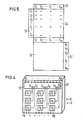
- Figures 4 and 5 show a detector array and the principle of pattern recognition.
- FIG. 1 shows a sensor D with a MOS detector 10 with an integrated heating resistor 6 for the optional setting of a predeterminable operating temperature.
- a protective layer 3 of silicon dioxide in the p-type silicon. 4 with a gate oxide layer is preferably made of thermally generated silicon dioxide.
- the metal layer 5 made of, for example, palladium is the catalytically active layer. It has the connection 15.
- an area 6 is provided in the substrate body 21, which is, for example, degenerate n-doped.
- the substrate body 21 At one end of this area 6, there is an aluminum electrode 7 on the surface of the substrate body 21 conclusion H arranged.
- This arrangement is a heating resistor. Its second electrode can be the substrate body 21.
- the substrate body is denoted by 21, its connection by 121 and 5 by the catalytically active metal layer.
- 71 indicates a second electrode for the resistance track of area 6 serving as a heater.
- 31 is an optional zeolite layer, e.g. selected from known zeolites.
- zeolite layer 31 different time constants can thus be used for the detection of different gases. This results in different time constants not only for operating temperatures and / or modulation frequencies that can be optionally specified, but also "two-dimensionally" due to the zeolites of layer 31 selected in each case.
- Figure 3 shows an arrangement which is preferably suitable for calibration, but also for operation according to the invention.
- the sensor Di is arranged in a volume of a measuring chamber M, indicated by 11. This volume 11 has two inlets 12 and 13 and an outlet 14. 16 and 17 are each a solenoid valve for controlling gas surges.
- the gas to be detected is supplied via line 18.
- the line 19 is provided for the supply of a reference gas.
- the i-th detector Di has the connection 15i.
- FIG. 4 shows a schematic illustration of a detector array with nine individual detectors D1 to D9 and an evaluation 55.
- the array preferably has an integrated structure on a substrate body 21 made of preferably semiconductor material.
- the detectors D1 to D9 are brought individually to different temperatures or one or more of these detectors are brought to a temperature different from the other detectors (operated at "room temperature”).
- the indicated power supply lines H 1 to H 9 serve this purpose.
- the heating current can also be modulated, which leads to corresponding characteristic sensitivity, as set out above. Different characteristic sensitivity can be achieved with different selective modulation frequencies.
- FIG. 5 shows the pattern of a pattern recognition, with the aid of which an (also simultaneous) evaluation of the output signals S1 to Sm given by the time constant values of the individual sensors D 1 to D m can be carried out.
- FIG. 4 shows the principle of a gas sensor with a detector array with the individual detectors D1, D2 to Dm.
- the individual detectors D1, D2 For the individual gases or for the gas components G1, G2, G3 ... Gi ... Gn of a gas mixture, the individual detectors D1, D2 ... have the sensitivities specified in the matrix 54 in the respective associated column of the matrix 54.
- a pulse sign means high sensitivity or main sensitivity
- a St. Andrew's cross means significantly lower sensitivity
- a minus sign stands for insensitivity of the relevant single detector to the relevant gas component Gl, G2 ...
- the single detectors form row 52 and the gas components column 53 to the matrix 54. It should be noted that such a matrix, for example also only has two individual detectors D1 and D2.
- the signal S1 for example, is the determined value of the time constant (as explained above) of the individual detector D1 compared to the gas components G1, G2 to Gn. It also contains the information that the single detector D1 is insensitive to the gas components Gi and Gn.
- Corresponding time constant values result in the remaining signals S2 to Sm. If, for example, the gas components G2 and Gn are not present, a signal S'l then to be obtained differs from the signal S1 in that the signal component which is otherwise based on the gas component G2, in this case even a main sensitivity of the single detector compared to the gas component G2, is missing in the signal S'l. The absence of the gas component Gn obviously does not contribute to the difference between S'1 and S1.
- the signal S'm which occurs, for example, in the absence of the gas components G2 and Gn differs from the signal Sm in that the signal component the main sensitivity to the gas component Gn and the lower sensitivity to the gas component G2, ie the time constant components given by these gases are missing.
- the detector signals i.e. in the respective individual case, the signals S1 to Sm actually occurring for a gas component mixture x are supplied.
- This matrix 55 is able to calculate from the total of the signals S1 to Sm, i.e. to conclude from the number of m signals the presence or absence of individual gas components from a number n of gas components programmed into the pattern recognition matrix.
- the number m can even be (by a speaking relative number) smaller than the number n. It should be noted that the presence of a non-programmed gas (due to an unassignable part in the measured time constant) can at least be determined.
- the a ij with j different from i are the cross-sensitivities mentioned above.
- the aim was and is to develop such detectors which have the smallest possible cross-sensitivities, ie in which the matrix elements a ij for i different from j are as small as possible compared to those Matrix elements a ij with i are equal to j.
- This requires at least one individual detector for each gas component, ie m must be equal to or greater than n.
- the cross-sensitivities a ij with i different from j are used and evaluated to an extent essential to the invention.
- Cross-sensitivities are desired in the invention, which is even contrary to the state of development to date.
- the use of the cross-sensitivities is based on the fact that in the invention the number m of the individual detector can easily be smaller than the number n of the gas components to be detected.
- a ij are constant values of the respective sensitivity of the relevant individual detector Si, including the value zero, a linear system of equations results, which is solved with the aid of the pattern recognition matrix 55. If the a ij is a function of the presence of the other gases G ... that are present beyond the gas component Gj, the pattern recognition matrix 55 is enabled to solve this system of equations with the help of appropriate calibration.
- the corresponding calibrations of the detector array consisting of the individual detectors are to be carried out using known, different gas mixtures.
- the pattern recognition matrix 55 is then equipped in such a way that it is able to carry out iterations, with the aid of which unambiguous assignment is also possible in this case, i.e. the solution can be obtained in a known mathematical way with the aid of the pattern recognition matrix 5.
- the method of calibration and pattern recognition can also be understood mathematically as a way of forming correlation coefficients.
- the correlation coefficients ⁇ j are determined in accordance with the following regulation:
- the correlation coefficient ß j then indicates the proportion of the gas components G j to be determined.
- the pattern recognition matrix 55 has the outputs Al to An given in column 57 for the number n of gas components G1 to Gn.
- the individual values for the gas components concerned can be taken from these outputs A.
Landscapes
- Chemical & Material Sciences (AREA)
- Health & Medical Sciences (AREA)
- Life Sciences & Earth Sciences (AREA)
- Engineering & Computer Science (AREA)
- General Physics & Mathematics (AREA)
- Pathology (AREA)
- Immunology (AREA)
- Physics & Mathematics (AREA)
- Analytical Chemistry (AREA)
- Biochemistry (AREA)
- General Health & Medical Sciences (AREA)
- Food Science & Technology (AREA)
- Medicinal Chemistry (AREA)
- Combustion & Propulsion (AREA)
- Microelectronics & Electronic Packaging (AREA)
- Molecular Biology (AREA)
- Chemical Kinetics & Catalysis (AREA)
- Electrochemistry (AREA)
- Investigating Or Analyzing Materials By The Use Of Fluid Adsorption Or Reactions (AREA)
- Investigating Or Analyzing Materials By The Use Of Electric Means (AREA)
- Investigating Or Analyzing Non-Biological Materials By The Use Of Chemical Means (AREA)
Priority Applications (1)
| Application Number | Priority Date | Filing Date | Title |
|---|---|---|---|
| AT86107134T ATE66745T1 (de) | 1985-05-30 | 1986-05-26 | Betriebsverfahren fuer einen sensor fuer gasanalyse. |
Applications Claiming Priority (2)
| Application Number | Priority Date | Filing Date | Title |
|---|---|---|---|
| DE19853519410 DE3519410A1 (de) | 1985-05-30 | 1985-05-30 | Betriebsverfahren und sensor fuer gasanalyse |
| DE3519410 | 1985-05-30 |
Publications (3)
| Publication Number | Publication Date |
|---|---|
| EP0203561A2 true EP0203561A2 (fr) | 1986-12-03 |
| EP0203561A3 EP0203561A3 (en) | 1989-08-30 |
| EP0203561B1 EP0203561B1 (fr) | 1991-08-28 |
Family
ID=6272021
Family Applications (1)
| Application Number | Title | Priority Date | Filing Date |
|---|---|---|---|
| EP86107134A Expired - Lifetime EP0203561B1 (fr) | 1985-05-30 | 1986-05-26 | Procédé d'utilisation un capteur pour l'analyse de gaz |
Country Status (6)
| Country | Link |
|---|---|
| US (1) | US4703646A (fr) |
| EP (1) | EP0203561B1 (fr) |
| AT (1) | ATE66745T1 (fr) |
| CA (1) | CA1248176A (fr) |
| DE (2) | DE3519410A1 (fr) |
| ES (1) | ES8707613A1 (fr) |
Cited By (7)
| Publication number | Priority date | Publication date | Assignee | Title |
|---|---|---|---|---|
| EP0237277A3 (fr) * | 1986-03-12 | 1988-06-01 | THORN EMI plc | Dispositif sensible à gaz |
| EP0317871A3 (fr) * | 1987-11-24 | 1991-03-06 | Siemens Aktiengesellschaft | Capteur pour détecter des gaz |
| EP0431910A1 (fr) * | 1989-12-06 | 1991-06-12 | THE GENERAL ELECTRIC COMPANY, p.l.c. | Détection de substances chimiques |
| EP0492700A1 (fr) * | 1990-12-13 | 1992-07-01 | Interuniversitair Microelektronica Centrum Vzw | Détecteur du type diode |
| WO1995004927A1 (fr) * | 1993-08-05 | 1995-02-16 | Capteur Sensors & Analysers Ltd. | Surveillance de capteurs de gaz a electrodes multiples |
| EP0740151A1 (fr) * | 1995-04-24 | 1996-10-30 | Motorola, Inc. | Sonde chimique avec transistor à effet de champ pour mesurer le potentiel de surface d'une électrode de grille |
| WO1999001761A1 (fr) * | 1997-07-05 | 1999-01-14 | Osmetech Plc | Appareil et procede d'echantillonnage de gaz |
Families Citing this family (51)
| Publication number | Priority date | Publication date | Assignee | Title |
|---|---|---|---|---|
| US4896143A (en) * | 1987-04-24 | 1990-01-23 | Quantum Group, Inc. | Gas concentration sensor with dose monitoring |
| DE3729286A1 (de) * | 1987-09-02 | 1989-03-16 | Draegerwerk Ag | Messgeraet zur analyse eines gasgemisches |
| US5037761A (en) * | 1987-09-03 | 1991-08-06 | Elsag International B.V. | Method of applying an automotive type oxygen sensor for use in an industrial process analyzer |
| DE3736199A1 (de) * | 1987-10-26 | 1989-05-03 | Siemens Ag | Sensoranordnung zur gasanalyse |
| DE3736200A1 (de) * | 1987-10-26 | 1989-05-03 | Siemens Ag | Verfahren zum betrieb eines nach dem kalorimeterprinzip arbeitenden halbleitergassensors mit mehreren sensorelementen |
| DE3805734A1 (de) * | 1988-02-24 | 1989-08-31 | Bosch Gmbh Robert | Verwendung von zeolithen als spezifische adsorbentien fuer no(pfeil abwaerts)x(pfeil abwaerts) und co |
| US4927768A (en) * | 1988-06-29 | 1990-05-22 | Uop | Grown crystalline sensor and method for sensing |
| US4904518A (en) * | 1988-06-29 | 1990-02-27 | Uop | Multiphase composite and processes for preparing same |
| DE4007375C2 (de) * | 1989-04-18 | 1998-05-07 | Siemens Ag | Sensoranordnung mit einem Gassensor und einem Katalysator zum Nachweis von gasförmigen Verbindungen |
| US5338515A (en) * | 1990-08-17 | 1994-08-16 | Catalytica, Inc. | SO2 sensor |
| DE4227727C2 (de) * | 1992-08-21 | 1994-09-15 | Buna Gmbh | Verfahren zur Zustandserkennung gasförmiger und flüssiger Medien mittels Multisensorsystemen |
| GB9306594D0 (en) * | 1993-03-30 | 1993-05-26 | Univ Keele | Sensor |
| DE4316196C2 (de) * | 1993-05-14 | 1994-07-28 | Guenter Dr Vos | Verfahren und Vorrichtung zur Gasanalyse |
| DE4401570A1 (de) * | 1994-01-20 | 1995-07-27 | Rwe Energie Ag | Einrichtung für die Messung von Zustandsgrößen in Gasen mit zumindest einem Halbleiter-Gassensor |
| JP3032677B2 (ja) * | 1994-03-24 | 2000-04-17 | アヴェンティス・リサーチ・ウント・テクノロジーズ・ゲーエムベーハー・ウント・コー・カーゲー | 燃料蒸気判別方法及び装置 |
| US5494826A (en) * | 1994-04-18 | 1996-02-27 | Gas Research Institute, Inc. | Microcalorimeter sensor for the measurement of heat content of natural gas |
| US5495747A (en) * | 1994-09-30 | 1996-03-05 | Mine Safety Appliances Company | Device for detecting gases for use in diffusion and forced flow modes |
| US5823044A (en) * | 1997-04-30 | 1998-10-20 | Ford Global Technologies, Inc. | Method for selective gas sensors based on nonlinear gas reactions |
| US5831145A (en) * | 1997-04-30 | 1998-11-03 | Ford Global Technologies, Inc. | Method of introducing selectivity to nonselective gas sensors |
| FR2763130B1 (fr) * | 1997-05-12 | 1999-09-03 | Motorola Semiconducteurs | Procede et systeme capteur permettant de determiner la concentration en une espece chimique |
| DE19808663C2 (de) * | 1998-03-02 | 2001-05-23 | Epcos Ag | System zur Branderkennung und Betriebsverfahren für dieses System |
| US6827903B2 (en) * | 2001-10-26 | 2004-12-07 | Leco Corporation | Inert gas fusion analyzer |
| US6879936B2 (en) * | 2002-01-09 | 2005-04-12 | Fisher Controls International Llc | Diagnostic apparatus and methods for a chemical detection system |
| US20040142489A1 (en) * | 2003-01-16 | 2004-07-22 | Prohaska Otto J. | Method and apparatus for determining a concentration of a component in an unknown mixture |
| US20040173004A1 (en) * | 2003-03-05 | 2004-09-09 | Eblen John P. | Robust palladium based hydrogen sensor |
| JP4724426B2 (ja) * | 2004-03-30 | 2011-07-13 | シチズンホールディングス株式会社 | ガスセンサ用検知素子および接触燃焼式ガスセンサ |
| US7582222B2 (en) * | 2004-07-30 | 2009-09-01 | Boise State University | Transition metal-doped oxide semiconductor exhibiting room-temperature ferromagnetism |
| DE102005008051A1 (de) * | 2005-02-22 | 2006-08-24 | Siemens Ag | Gassensor und Verfahren zu dessen Betrieb |
| US7611612B2 (en) | 2005-07-14 | 2009-11-03 | Ceramatec, Inc. | Multilayer ceramic NOx gas sensor device |
| WO2008153603A1 (fr) * | 2006-12-22 | 2008-12-18 | Boise State University | Détecteur magnétique de gaz et procédés utilisant des nanoparticules d'hématite antiferromagnétique |
| WO2009126568A1 (fr) * | 2008-04-06 | 2009-10-15 | H2Scan Corporation | Revêtements protecteurs pour capteurs de gaz à semi-conducteurs utilisant des métaux catalytiques |
| JP2010122056A (ja) * | 2008-11-19 | 2010-06-03 | Ngk Spark Plug Co Ltd | センサ素子評価装置 |
| CN101871904B (zh) * | 2009-04-25 | 2013-06-05 | 鸿富锦精密工业(深圳)有限公司 | 气体检测装置、气体检测系统及气体检测装置的制作方法 |
| DE102009047354A1 (de) * | 2009-12-01 | 2011-06-09 | Robert Bosch Gmbh | Verfahren und Steuergerät zur Detektion einer Gaskonzentration eines Gases aus einem Gasgemisch |
| DE102011002856A1 (de) | 2011-01-19 | 2012-07-19 | Robert Bosch Gmbh | Verfahren zur Erfassung mindestens eines Parameters eines Gases |
| US9506888B2 (en) | 2011-04-13 | 2016-11-29 | 3M Innovative Properties Company | Vapor sensor including sensor element with integral heating |
| US9279792B2 (en) | 2011-04-13 | 2016-03-08 | 3M Innovative Properties Company | Method of using an absorptive sensor element |
| WO2012141925A1 (fr) | 2011-04-13 | 2012-10-18 | 3M Innovative Properties Company | Procédé de détection de composés organiques volatils |
| EP2810059A4 (fr) * | 2012-01-30 | 2015-09-23 | Univ King Abdullah Sci & Tech | Capteur de gaz |
| US9164080B2 (en) | 2012-06-11 | 2015-10-20 | Ohio State Innovation Foundation | System and method for sensing NO |
| ES2486891B1 (es) * | 2013-01-17 | 2015-10-27 | Sgenia Soluciones Sl | Método de análisis de un gas y nariz artificial |
| US9395344B2 (en) * | 2013-02-06 | 2016-07-19 | Veris Industries, Llc | Gas sensor with thermal measurement compensation |
| GB2520251A (en) * | 2013-11-12 | 2015-05-20 | Emma Newton | Hand held device for the detection of trace gases |
| CN105761439B (zh) * | 2014-12-17 | 2019-09-13 | 富泰华工业(深圳)有限公司 | 侦测空气污染的移动终端、系统及方法 |
| US20160187279A1 (en) * | 2014-12-24 | 2016-06-30 | Intel Corporation | Metal oxide gas sensor array devices, systems, and associated methods |
| EP3163295B1 (fr) * | 2015-11-02 | 2020-09-30 | Alpha M.O.S. | Système et méthode de caractérisation d'un échantillon de gaz |
| US10330624B2 (en) | 2016-07-02 | 2019-06-25 | Intel Corporation | Metal oxide gas sensor array devices, systems, and associated methods |
| US10830722B2 (en) | 2017-01-09 | 2020-11-10 | King Abdullah Unviersity Of Science And Technology | Gas sensors and methods of detecting gas |
| US10803382B2 (en) | 2017-06-16 | 2020-10-13 | Intel Corporation | Gas identification apparatus and machine learning method |
| WO2020262252A1 (fr) * | 2019-06-28 | 2020-12-30 | 京セラ株式会社 | Dispositif de détection de gaz |
| DE102020114982A1 (de) | 2020-06-05 | 2021-12-09 | Dräger Safety AG & Co. KGaA | Gasmessgerät und Verfahren zum Messen von Dicyan in Anwesenheit von Cyanwasserstoff |
Family Cites Families (13)
| Publication number | Priority date | Publication date | Assignee | Title |
|---|---|---|---|---|
| US3865550A (en) * | 1970-08-26 | 1975-02-11 | Nat Res Dev | Semi-conducting gas sensitive devices |
| DE2407110C3 (de) * | 1974-02-14 | 1981-04-23 | Siemens AG, 1000 Berlin und 8000 München | Sensor zum Nachweis einer in einem Gas oder einer Flüssigkeit einthaltenen Substanz |
| US3961248A (en) * | 1974-07-02 | 1976-06-01 | Nohmi Bosai Kogyo Co. Ltd. | Gas detector using gas sensing elements exhibiting different response characteristics |
| US4020830A (en) * | 1975-03-12 | 1977-05-03 | The University Of Utah | Selective chemical sensitive FET transducers |
| JPS5639454A (en) * | 1979-09-10 | 1981-04-15 | Olympus Optical Co Ltd | Chemical suybstance detector by using chemical sensitive element with structure of insulated-gate field-effect transistor |
| DE3030448A1 (de) * | 1980-08-12 | 1982-03-11 | Brown, Boveri & Cie Ag, 6800 Mannheim | Verfahren und vorrichtung fuer die von temperaturschwankungen unbeeinflusste bestimmung des sauerstoffgehaltes in gasen |
| JPS5766347A (en) * | 1980-10-09 | 1982-04-22 | Hitachi Ltd | Detector for mixture gas |
| DE3047782A1 (de) * | 1980-12-18 | 1982-07-08 | Drägerwerk AG, 2400 Lübeck | Schaltungsanordnung zur korrektur der sensorausgangsgroesse |
| US4423407A (en) * | 1981-02-27 | 1983-12-27 | Dart Industries Inc. | Apparatus and method for measuring the concentration of gases |
| US4502321A (en) * | 1981-02-27 | 1985-03-05 | Capital Controls | Apparatus and method for measuring the concentration of gases |
| US4562725A (en) * | 1982-07-31 | 1986-01-07 | Shimadzu Corporation | Moisture sensor and a process for the production thereof |
| CH665908A5 (de) * | 1983-08-30 | 1988-06-15 | Cerberus Ag | Vorrichtung zum selektiven detektieren der gasfoermigen bestandteile von gasgemischen in luft mittels eines gassensors. |
| CH668648A5 (de) * | 1984-04-04 | 1989-01-13 | Cerberus Ag | Verfahren und vorrichtung zum nachweis von reduzierenden gasen in einem gasgemisch. |
-
1985
- 1985-05-30 DE DE19853519410 patent/DE3519410A1/de not_active Withdrawn
-
1986
- 1986-05-26 AT AT86107134T patent/ATE66745T1/de not_active IP Right Cessation
- 1986-05-26 DE DE8686107134T patent/DE3681070D1/de not_active Expired - Lifetime
- 1986-05-26 EP EP86107134A patent/EP0203561B1/fr not_active Expired - Lifetime
- 1986-05-28 CA CA000510136A patent/CA1248176A/fr not_active Expired
- 1986-05-29 US US06/867,965 patent/US4703646A/en not_active Expired - Fee Related
- 1986-05-30 ES ES555563A patent/ES8707613A1/es not_active Expired
Cited By (9)
| Publication number | Priority date | Publication date | Assignee | Title |
|---|---|---|---|---|
| EP0237277A3 (fr) * | 1986-03-12 | 1988-06-01 | THORN EMI plc | Dispositif sensible à gaz |
| EP0317871A3 (fr) * | 1987-11-24 | 1991-03-06 | Siemens Aktiengesellschaft | Capteur pour détecter des gaz |
| EP0431910A1 (fr) * | 1989-12-06 | 1991-06-12 | THE GENERAL ELECTRIC COMPANY, p.l.c. | Détection de substances chimiques |
| EP0492700A1 (fr) * | 1990-12-13 | 1992-07-01 | Interuniversitair Microelektronica Centrum Vzw | Détecteur du type diode |
| WO1995004927A1 (fr) * | 1993-08-05 | 1995-02-16 | Capteur Sensors & Analysers Ltd. | Surveillance de capteurs de gaz a electrodes multiples |
| GB2296572A (en) * | 1993-08-05 | 1996-07-03 | Capteur Sensors & Analysers | Monitoring of multiple-electrode gas sensors |
| EP0740151A1 (fr) * | 1995-04-24 | 1996-10-30 | Motorola, Inc. | Sonde chimique avec transistor à effet de champ pour mesurer le potentiel de surface d'une électrode de grille |
| WO1999001761A1 (fr) * | 1997-07-05 | 1999-01-14 | Osmetech Plc | Appareil et procede d'echantillonnage de gaz |
| US6431016B1 (en) | 1997-07-05 | 2002-08-13 | Osmetech Plc | Apparatus and methods for gas sampling |
Also Published As
| Publication number | Publication date |
|---|---|
| EP0203561A3 (en) | 1989-08-30 |
| ES555563A0 (es) | 1987-08-01 |
| US4703646A (en) | 1987-11-03 |
| ATE66745T1 (de) | 1991-09-15 |
| ES8707613A1 (es) | 1987-08-01 |
| EP0203561B1 (fr) | 1991-08-28 |
| DE3519410A1 (de) | 1986-12-04 |
| DE3681070D1 (de) | 1991-10-02 |
| CA1248176A (fr) | 1989-01-03 |
Similar Documents
| Publication | Publication Date | Title |
|---|---|---|
| EP0203561B1 (fr) | Procédé d'utilisation un capteur pour l'analyse de gaz | |
| DE3519397A1 (de) | Sensor fuer gasanalyse bzw. -detektion | |
| DE69416842T2 (de) | Verfahren und vorrichtung zum nachweis von substanzen sowie anwendungen | |
| DE3507386A1 (de) | Sensor-anordnung fuer die feststellung von toxischem gas | |
| DE3519435A1 (de) | Sensor fuer gasanalyse | |
| DE69414258T2 (de) | Überwachung von mehrfachelektroden gassensoren | |
| DE69516274T2 (de) | Feuchtigkeitssensor | |
| EP0141089A2 (fr) | Appareil pour la détermination sélective des composants de mélanges gazeux | |
| DE60127292T2 (de) | Verfahren und vorrichtung zur gasentladungsspektroskopie | |
| DE1673032A1 (de) | Verfahren und Vorrichtung zum Messen der Gas- oder Dampfdurchlaessigkeit von Filmen | |
| DE69020343T2 (de) | Pseudokontinuierliches verfahren zum abfragen eines detektors für oxydierbares gas. | |
| DE19924906C2 (de) | Halbleiter-Gassensor, Gassensorsystem und Verfahren zur Gasanalyse | |
| DE19861198B4 (de) | Sensor für die Untersuchung von Abgasen und Untersuchungsverfahren | |
| DE4227727C2 (de) | Verfahren zur Zustandserkennung gasförmiger und flüssiger Medien mittels Multisensorsystemen | |
| DE10209760A1 (de) | Mikro-Brennstoffzellen-Sensoreinrichtung und Verfahren zum Anpasen der Sensoransprechzeit | |
| EP1193488A1 (fr) | Procede et dispositif pour determiner la nature de gaz naturel | |
| DE10106171A1 (de) | Gassensor | |
| DE3877518T2 (de) | Detektor fuer brennbare gase mit temperaturstabilisierung. | |
| DE102009052957A1 (de) | Gassensor mit Prüfgasgenerator | |
| Chambon et al. | A metallic oxide gas sensor array for a selective detection of the CO and NH3 gases | |
| DE69635160T2 (de) | Vorrichtung zur vergrösserung der sensorselektivität | |
| DE3519436A1 (de) | Sensor fuer gasanalyse | |
| DE19932048A1 (de) | Meßfühler zur Bestimmung einer Konzentration von Gaskomponenten in Gasgemischen | |
| DE19713194A1 (de) | Verfahren und Anordnung zum Erkennen komplexer Gas-, Geruchs-, Aromamuster einer jeweiligen Substanz auf der Basis der Massenspektroskopie | |
| EP0665428B1 (fr) | Dispositif de mesure de paramètres de gaz utilisant au moins un capteur de gaz semi-conducteur |
Legal Events
| Date | Code | Title | Description |
|---|---|---|---|
| PUAI | Public reference made under article 153(3) epc to a published international application that has entered the european phase |
Free format text: ORIGINAL CODE: 0009012 |
|
| AK | Designated contracting states |
Kind code of ref document: A2 Designated state(s): AT BE CH DE FR GB IT LI NL SE |
|
| PUAL | Search report despatched |
Free format text: ORIGINAL CODE: 0009013 |
|
| AK | Designated contracting states |
Kind code of ref document: A3 Designated state(s): AT BE CH DE FR GB IT LI NL SE |
|
| 17P | Request for examination filed |
Effective date: 19891026 |
|
| 17Q | First examination report despatched |
Effective date: 19901126 |
|
| GRAA | (expected) grant |
Free format text: ORIGINAL CODE: 0009210 |
|
| AK | Designated contracting states |
Kind code of ref document: B1 Designated state(s): AT BE CH DE FR GB IT LI NL SE |
|
| PG25 | Lapsed in a contracting state [announced via postgrant information from national office to epo] |
Ref country code: IT Free format text: LAPSE BECAUSE OF FAILURE TO SUBMIT A TRANSLATION OF THE DESCRIPTION OR TO PAY THE FEE WITHIN THE PRE;WARNING: LAPSES OF ITALIAN PATENTS WITH EFFECTIVE DATE BEFORE 2007 MAY HAVE OCCURRED AT ANY TIME BEFORE 2007. THE CORRECT EFFECTIVE DATE MAY BE DIFFERENT FROM THE ONE RECORDED.SCRIBED TIME-LIMIT Effective date: 19910828 Ref country code: BE Effective date: 19910828 Ref country code: NL Effective date: 19910828 Ref country code: GB Effective date: 19910828 Ref country code: FR Effective date: 19910828 Ref country code: SE Effective date: 19910828 |
|
| REF | Corresponds to: |
Ref document number: 66745 Country of ref document: AT Date of ref document: 19910915 Kind code of ref document: T |
|
| REF | Corresponds to: |
Ref document number: 3681070 Country of ref document: DE Date of ref document: 19911002 |
|
| EN | Fr: translation not filed | ||
| NLV1 | Nl: lapsed or annulled due to failure to fulfill the requirements of art. 29p and 29m of the patents act | ||
| GBV | Gb: ep patent (uk) treated as always having been void in accordance with gb section 77(7)/1977 [no translation filed] | ||
| PG25 | Lapsed in a contracting state [announced via postgrant information from national office to epo] |
Ref country code: AT Effective date: 19920526 |
|
| PG25 | Lapsed in a contracting state [announced via postgrant information from national office to epo] |
Ref country code: CH Effective date: 19920531 Ref country code: LI Effective date: 19920531 |
|
| PLBE | No opposition filed within time limit |
Free format text: ORIGINAL CODE: 0009261 |
|
| STAA | Information on the status of an ep patent application or granted ep patent |
Free format text: STATUS: NO OPPOSITION FILED WITHIN TIME LIMIT |
|
| PGFP | Annual fee paid to national office [announced via postgrant information from national office to epo] |
Ref country code: DE Payment date: 19920724 Year of fee payment: 7 |
|
| 26N | No opposition filed | ||
| REG | Reference to a national code |
Ref country code: CH Ref legal event code: PL |
|
| PG25 | Lapsed in a contracting state [announced via postgrant information from national office to epo] |
Ref country code: DE Effective date: 19940201 |