EP0203631A2 - Ringdichtung mit Flansch für Druckfass aus Kunststoff - Google Patents
Ringdichtung mit Flansch für Druckfass aus Kunststoff Download PDFInfo
- Publication number
- EP0203631A2 EP0203631A2 EP86200588A EP86200588A EP0203631A2 EP 0203631 A2 EP0203631 A2 EP 0203631A2 EP 86200588 A EP86200588 A EP 86200588A EP 86200588 A EP86200588 A EP 86200588A EP 0203631 A2 EP0203631 A2 EP 0203631A2
- Authority
- EP
- European Patent Office
- Prior art keywords
- internal
- pressure tank
- annular
- axis
- face
- Prior art date
- Legal status (The legal status is an assumption and is not a legal conclusion. Google has not performed a legal analysis and makes no representation as to the accuracy of the status listed.)
- Withdrawn
Links
Images

Classifications
-
- F—MECHANICAL ENGINEERING; LIGHTING; HEATING; WEAPONS; BLASTING
- F17—STORING OR DISTRIBUTING GASES OR LIQUIDS
- F17C—VESSELS FOR CONTAINING OR STORING COMPRESSED, LIQUEFIED OR SOLIDIFIED GASES; FIXED-CAPACITY GAS-HOLDERS; FILLING VESSELS WITH, OR DISCHARGING FROM VESSELS, COMPRESSED, LIQUEFIED, OR SOLIDIFIED GASES
- F17C1/00—Pressure vessels, e.g. gas cylinder, gas tank, replaceable cartridge
- F17C1/16—Pressure vessels, e.g. gas cylinder, gas tank, replaceable cartridge constructed of plastics materials
-
- F—MECHANICAL ENGINEERING; LIGHTING; HEATING; WEAPONS; BLASTING
- F17—STORING OR DISTRIBUTING GASES OR LIQUIDS
- F17C—VESSELS FOR CONTAINING OR STORING COMPRESSED, LIQUEFIED OR SOLIDIFIED GASES; FIXED-CAPACITY GAS-HOLDERS; FILLING VESSELS WITH, OR DISCHARGING FROM VESSELS, COMPRESSED, LIQUEFIED, OR SOLIDIFIED GASES
- F17C13/00—Details of vessels or of the filling or discharging of vessels
- F17C13/002—Details of vessels or of the filling or discharging of vessels for vessels under pressure
-
- F—MECHANICAL ENGINEERING; LIGHTING; HEATING; WEAPONS; BLASTING
- F17—STORING OR DISTRIBUTING GASES OR LIQUIDS
- F17C—VESSELS FOR CONTAINING OR STORING COMPRESSED, LIQUEFIED OR SOLIDIFIED GASES; FIXED-CAPACITY GAS-HOLDERS; FILLING VESSELS WITH, OR DISCHARGING FROM VESSELS, COMPRESSED, LIQUEFIED, OR SOLIDIFIED GASES
- F17C2203/00—Vessel construction, in particular walls or details thereof
- F17C2203/06—Materials for walls or layers thereof; Properties or structures of walls or their materials
- F17C2203/0634—Materials for walls or layers thereof
- F17C2203/0658—Synthetics
- F17C2203/0663—Synthetics in form of fibers or filaments
- F17C2203/0673—Polymers
-
- F—MECHANICAL ENGINEERING; LIGHTING; HEATING; WEAPONS; BLASTING
- F17—STORING OR DISTRIBUTING GASES OR LIQUIDS
- F17C—VESSELS FOR CONTAINING OR STORING COMPRESSED, LIQUEFIED OR SOLIDIFIED GASES; FIXED-CAPACITY GAS-HOLDERS; FILLING VESSELS WITH, OR DISCHARGING FROM VESSELS, COMPRESSED, LIQUEFIED, OR SOLIDIFIED GASES
- F17C2205/00—Vessel construction, in particular mounting arrangements, attachments or identifications means
- F17C2205/03—Fluid connections, filters, valves, closure means or other attachments
- F17C2205/0302—Fittings, valves, filters, or components in connection with the gas storage device
- F17C2205/0305—Bosses, e.g. boss collars
Definitions
- the present invention relates to an annular closure with a neck intended for mounting on the open central ends, ending in a spherical manner, of cylindrical pressure tanks.
- These pressure tanks made of synthetic material normally consist of a relatively thin internal tank for which thermoplastic synthetic materials (acrylonitrile-butadienestyrene copolymer, polypropene, polythene) as well as thermosetting materials (for example reinforced polyester resins) can be used. by glass fibers, vinyl resins reinforced by glass fibers, epoxy resins reinforced by glass fibers).
- This internal tank also known as a "jacket" provides water resistance and chemical resistance of the tank, but offers no mechanical resistance. To obtain the latter, the shirt is surrounded by a continuously extending wire, impregnated or not with resin. This winding can be done in different ways, namely polar, héiico ') daie or radial.
- inlets and outlets must be constructed, with the same physical and chemical resistance and the same watertightness as the tank itself.
- These inlets and outlets are normally found on the lower and / or upper side of the tank and are called annular neck closures.
- neck closures can be connected supply and evacuation pipes, internal distribution systems, electrical resistances, regeneration valves, etc.
- a first type is bonded to the internal tank
- a second type consists of two parts, an O-ring being mounted in each part, rings which are screwed one on the other.
- the major drawback of the glued type is that the glue, under the pressure of the liquid in the reservoir, breaks down over time, so that the liquid leaves between the neck closure and the reservoir, with the result that the latter n is more waterproof.
- part of the neck closure is not surrounded by the continuously extending wire.
- the axis of the covered part is located at another angle.
- the object of the present invention is to eliminate these imperfections and to offer a neck closure which provides good permanent water tightness and has good mechanical resistance.
- the neck closure according to the invention consists, on the one hand, of an annular internal part, the end of which located inside the pressure tank, has a larger diameter than that of the end. open central, spherically terminating, of said pressure tank, while on this end are provided lugs which fit into recesses made for this purpose in said opening of the pressure tank, and a large fraction of the face external of the other end is provided with a thread and, on the other hand, by an annular external part whose internal face is provided with a screw, so that this external part can be screwed onto the end with a thread of the internal part.
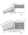
- the best neck closure known up to now consists of two parts 1 and 2. In each of these is mounted a sealing ring 3. It is clear that at the height of the point 4, an accumulation of liquid may occur. This liquid can then pass through the wall of the internal tank 5, so that the tank is no longer waterproof. In addition, this can result in the internal tank taking off. In addition, you cannot circle the collar closure all the way up, resulting in the tensions already mentioned.
- the neck closure according to the invention consists of an annular internal part 6 and an annular external part 7.
- the end 8 of the internal part 6 located in the pressure tank has a diameter which is greater than that of the spherical, open central end of this reservoir.
- On this end 8 are provided lugs 9, which fit into recesses 10 made for this purpose in the opening of the pressure tank.
- These lugs 9 and recesses 10 prevent that during and after mounting, a relative rotational movement of the pressure tank and the internal ring is still possible around the common axis of revolution of this internal ring and the cylindrical pressure tank .
- a large fraction of the internal face 11 of the internal part 6 is provided with a screw pitch 12.
- the internal face 13 of the external part 7 is also provided with a screw pitch 14, so that the two parts 6 and 7 can be screwed on top of each other.
- the annular internal part 6 has here received a shape which is obtained by rotating a rectangle 15 to which a triangular piece 16 is fixed, around the axis 17.
- the angle of inclination of the side 18 of the triangular part 16 with respect to the axis 17, is equal to the angle of inclination of the end 19 of the internal face of the pressure tank.
- a screw pitch 21 on the internal face 20 of the internal part 6 is provided a screw pitch 21, so that the appropriate accessory can be screwed into it.
- a semi-circular notch 12 in which an O-ring 23 is placed is still practical on the entire periphery of the side 18, a semi-circular notch 12 in which an O-ring 23 is placed.
- the annular external part has a shape which is obtained by rotating the triangular assembly 24 around the axis 17.
- the angle of inclination of the side 25 of the assembly 24 and the angle of inclination of the face internal 19 of the internal tank 5, with respect to the axis of symmetry 17 of this pressure tank, are equal.
- the inclination of the side 26 of the triangular assembly 24 is chosen so that this side is perpendicular to the axis of the continuous encirclement of the reservoir.
Landscapes
- Engineering & Computer Science (AREA)
- Mechanical Engineering (AREA)
- General Engineering & Computer Science (AREA)
- Pressure Vessels And Lids Thereof (AREA)
- Filling Or Discharging Of Gas Storage Vessels (AREA)
Applications Claiming Priority (2)
| Application Number | Priority Date | Filing Date | Title |
|---|---|---|---|
| BE0/215099A BE902543A (nl) | 1985-05-30 | 1985-05-30 | Halsafsluitring voor kunststof druktanks. |
| BE215099 | 1985-05-30 |
Publications (2)
| Publication Number | Publication Date |
|---|---|
| EP0203631A2 true EP0203631A2 (de) | 1986-12-03 |
| EP0203631A3 EP0203631A3 (de) | 1987-11-11 |
Family
ID=3843893
Family Applications (1)
| Application Number | Title | Priority Date | Filing Date |
|---|---|---|---|
| EP86200588A Withdrawn EP0203631A3 (de) | 1985-05-30 | 1986-04-07 | Ringdichtung mit Flansch für Druckfass aus Kunststoff |
Country Status (2)
| Country | Link |
|---|---|
| EP (1) | EP0203631A3 (de) |
| BE (1) | BE902543A (de) |
Cited By (20)
| Publication number | Priority date | Publication date | Assignee | Title |
|---|---|---|---|---|
| EP0398827A1 (de) * | 1989-05-18 | 1990-11-22 | Claude Léon Hembert | Vorrichtung zum Schutz der Enden eines Fluidbehälters aus Schichtmaterial |
| EP0821194A3 (de) * | 1996-07-24 | 1998-11-04 | MANNESMANN Aktiengesellschaft | Composite-Druckbehälter zur Speicherung von gasförmigen Medien unter Druck mit einem Liner aus Kunststoff |
| WO2001051844A3 (de) * | 2000-01-10 | 2002-02-07 | Ralph Funck | Druckbehälter zur speicherung von flüssigen und/oder gasförmigen medien unter druck, bestehend aus einem kunststoff-kernbehälter, der mit faserverstärkten kunststoffen verstärkt ist und verfahren zu dessen herstellung |
| WO2008026235A3 (en) * | 2007-04-16 | 2008-04-17 | Hydro System Treatement S R L | Tankoutlet |
| WO2010142303A1 (en) * | 2009-06-08 | 2010-12-16 | N.G.F. Inzeniering D.O.O. | Collar for high-pressure bottles and process for its construction |
| EP1586807A3 (de) * | 2004-04-13 | 2011-04-06 | "Stako" sp. z o.o. | Behälter aus Verbundwerkstoff und dessen Herstellungsverfahren |
| WO2011047752A1 (de) * | 2009-10-19 | 2011-04-28 | Kautex Maschinenbau Gmbh | Behälterhalsaufbau eines druckbehälters |
| DE112006003013B4 (de) * | 2005-11-08 | 2011-07-28 | Toyota Jidosha Kabushiki Kaisha, Aichi-ken | Tank |
| DE102010018700A1 (de) * | 2010-04-29 | 2011-11-03 | Magna Steyr Fahrzeugtechnik Ag & Co. Kg | Druckbehälter |
| WO2012066307A3 (en) * | 2010-11-15 | 2012-07-12 | Roger Carr | Vessel with associated collar |
| WO2015108429A1 (en) * | 2014-01-15 | 2015-07-23 | Techplast Spółka Z O.O. | High-pressure composite vessel and the method of manufacturing high-pressure composite vessel |
| WO2015197457A1 (de) * | 2014-06-27 | 2015-12-30 | Kautex Textron Gmbh & Co. Kg | Druckbehälter |
| WO2015197357A1 (de) * | 2014-06-27 | 2015-12-30 | Kautex Textron Gmbh & Co. Kg | Druckbehälter |
| CN106122765A (zh) * | 2016-08-24 | 2016-11-16 | 沈阳斯林达安科新技术有限公司 | 高分子材料内胆压力容器的密封结构 |
| CN107543026A (zh) * | 2016-06-29 | 2018-01-05 | 现代自动车株式会社 | 具有气密喷嘴结构的高压复合容器 |
| CN110805692A (zh) * | 2019-11-08 | 2020-02-18 | 亚普汽车部件股份有限公司 | 高压复合容器的密封结构及高压复合容器 |
| EP3795340A1 (de) | 2019-09-23 | 2021-03-24 | Adam Saferna | Hochdruckbehälter und verfahren zu dessen herstellung |
| DE102019007550A1 (de) * | 2019-10-30 | 2021-05-06 | Daimler Ag | Druckgasbehälter |
| DE102020134633A1 (de) | 2020-12-22 | 2022-06-23 | Voith Patent Gmbh | Drucktank für gasbetriebenes Fahrzeug |
| EP4610541A1 (de) * | 2024-02-29 | 2025-09-03 | A&S Composite s.r.o. | Druckbehälter aus dünnwandigem geschweisstem edelstahlbehälter und verfahren zu seiner herstellung |
Family Cites Families (3)
| Publication number | Priority date | Publication date | Assignee | Title |
|---|---|---|---|---|
| GB485203A (en) * | 1936-11-19 | 1938-05-17 | Simplex Electric Co Ltd | Improved means for securing immersion heaters and other fittings to plates, tanks and the like |
| US3182110A (en) * | 1958-11-05 | 1965-05-04 | White Consolidated Ind Inc | Method and apparatus for making fiber glass tank |
| US3282757A (en) * | 1962-12-14 | 1966-11-01 | Structural Fibers | Method of making a filament reinforced pressure vessel |
-
1985
- 1985-05-30 BE BE0/215099A patent/BE902543A/nl not_active IP Right Cessation
-
1986
- 1986-04-07 EP EP86200588A patent/EP0203631A3/de not_active Withdrawn
Cited By (32)
| Publication number | Priority date | Publication date | Assignee | Title |
|---|---|---|---|---|
| FR2647183A1 (fr) * | 1989-05-18 | 1990-11-23 | Hembert Claude | Dispositif pour proteger les extremites de reservoir de fluide en materiaux composites |
| EP0398827A1 (de) * | 1989-05-18 | 1990-11-22 | Claude Léon Hembert | Vorrichtung zum Schutz der Enden eines Fluidbehälters aus Schichtmaterial |
| EP0821194A3 (de) * | 1996-07-24 | 1998-11-04 | MANNESMANN Aktiengesellschaft | Composite-Druckbehälter zur Speicherung von gasförmigen Medien unter Druck mit einem Liner aus Kunststoff |
| WO2001051844A3 (de) * | 2000-01-10 | 2002-02-07 | Ralph Funck | Druckbehälter zur speicherung von flüssigen und/oder gasförmigen medien unter druck, bestehend aus einem kunststoff-kernbehälter, der mit faserverstärkten kunststoffen verstärkt ist und verfahren zu dessen herstellung |
| US7032767B2 (en) | 2000-01-10 | 2006-04-25 | Ralph Funck | Pressurized container for storing pressurized liquid and/or gaseous media, consisting of a plastic core container which is reinforced with fibre-reinforced plastics and a method for producing the same |
| EP1586807A3 (de) * | 2004-04-13 | 2011-04-06 | "Stako" sp. z o.o. | Behälter aus Verbundwerkstoff und dessen Herstellungsverfahren |
| DE112006003013B4 (de) * | 2005-11-08 | 2011-07-28 | Toyota Jidosha Kabushiki Kaisha, Aichi-ken | Tank |
| WO2008026235A3 (en) * | 2007-04-16 | 2008-04-17 | Hydro System Treatement S R L | Tankoutlet |
| WO2010142303A1 (en) * | 2009-06-08 | 2010-12-16 | N.G.F. Inzeniering D.O.O. | Collar for high-pressure bottles and process for its construction |
| WO2011047752A1 (de) * | 2009-10-19 | 2011-04-28 | Kautex Maschinenbau Gmbh | Behälterhalsaufbau eines druckbehälters |
| JP2013508622A (ja) * | 2009-10-19 | 2013-03-07 | コーテックス マシネンバウ ジーエムビーエイチ | 圧力容器の容器ネック構造 |
| US8505762B2 (en) | 2009-10-19 | 2013-08-13 | Kautex Maschinenbau Gmbh | Vessel neck construction of a pressure vessel |
| DE102010018700A1 (de) * | 2010-04-29 | 2011-11-03 | Magna Steyr Fahrzeugtechnik Ag & Co. Kg | Druckbehälter |
| US8640910B2 (en) | 2010-04-29 | 2014-02-04 | Magna Steyr Fahrzeugtechnik Ag & Co Kg | Pressure container |
| DE102010018700B4 (de) * | 2010-04-29 | 2019-05-09 | Magna Steyr Fahrzeugtechnik Ag & Co. Kg | Druckbehälter |
| WO2012066307A3 (en) * | 2010-11-15 | 2012-07-12 | Roger Carr | Vessel with associated collar |
| US10487981B2 (en) | 2014-01-15 | 2019-11-26 | Techplast Spolka Z O. O. | High-pressure composite vessel and the method of manufacturing high-pressure composite vessel |
| CN105705856A (zh) * | 2014-01-15 | 2016-06-22 | 塔克柏拉斯特有限责任公司 | 高压复合容器和制造高压复合容器的方法 |
| WO2015108429A1 (en) * | 2014-01-15 | 2015-07-23 | Techplast Spółka Z O.O. | High-pressure composite vessel and the method of manufacturing high-pressure composite vessel |
| CN105705856B (zh) * | 2014-01-15 | 2018-10-26 | 塔克柏拉斯特有限责任公司 | 高压复合容器和制造高压复合容器的方法 |
| RU2679689C1 (ru) * | 2014-01-15 | 2019-02-12 | Техпласт Спулка З О.О. | Сосуд высокого давления из композиционного материала и способ изготовления сосуда высокого давления из композиционного материала |
| WO2015197457A1 (de) * | 2014-06-27 | 2015-12-30 | Kautex Textron Gmbh & Co. Kg | Druckbehälter |
| WO2015197357A1 (de) * | 2014-06-27 | 2015-12-30 | Kautex Textron Gmbh & Co. Kg | Druckbehälter |
| CN107543026A (zh) * | 2016-06-29 | 2018-01-05 | 现代自动车株式会社 | 具有气密喷嘴结构的高压复合容器 |
| US11085584B2 (en) | 2016-06-29 | 2021-08-10 | Hyundai Motor Company | High-pressure composite container having gastight nozzle structure |
| CN106122765A (zh) * | 2016-08-24 | 2016-11-16 | 沈阳斯林达安科新技术有限公司 | 高分子材料内胆压力容器的密封结构 |
| EP3795340A1 (de) | 2019-09-23 | 2021-03-24 | Adam Saferna | Hochdruckbehälter und verfahren zu dessen herstellung |
| DE102019007550A1 (de) * | 2019-10-30 | 2021-05-06 | Daimler Ag | Druckgasbehälter |
| CN110805692A (zh) * | 2019-11-08 | 2020-02-18 | 亚普汽车部件股份有限公司 | 高压复合容器的密封结构及高压复合容器 |
| CN110805692B (zh) * | 2019-11-08 | 2022-05-20 | 亚普汽车部件股份有限公司 | 高压复合容器的密封结构及高压复合容器 |
| DE102020134633A1 (de) | 2020-12-22 | 2022-06-23 | Voith Patent Gmbh | Drucktank für gasbetriebenes Fahrzeug |
| EP4610541A1 (de) * | 2024-02-29 | 2025-09-03 | A&S Composite s.r.o. | Druckbehälter aus dünnwandigem geschweisstem edelstahlbehälter und verfahren zu seiner herstellung |
Also Published As
| Publication number | Publication date |
|---|---|
| EP0203631A3 (de) | 1987-11-11 |
| BE902543A (nl) | 1985-09-16 |
Similar Documents
| Publication | Publication Date | Title |
|---|---|---|
| EP0203631A2 (de) | Ringdichtung mit Flansch für Druckfass aus Kunststoff | |
| FR2683506A1 (fr) | Fermeture permettant de boire, pour des recipients destines a contenir un liquide. | |
| FR2709527A1 (fr) | Soupape d'aération pour un réservoir de carburant. | |
| FR3015442A1 (fr) | Dispositif de bouchage articule avec indicateur de premiere ouverture | |
| WO2000063611A1 (fr) | Dispositif de protection d'un recipient et recipient equipe de ce dispositif | |
| FR2727735A1 (fr) | Dispositif de purge ou de vidange d'un conduit | |
| FR2767794A1 (fr) | Ensemble de deux elements montes libres en rotation l'un par rapport a l'autre notamment pour un melangeur dans le domaine de la coloration capillaire | |
| EP0033745A1 (de) | Flasche mit dünnen wänden aus gesättigtem polyesterharz | |
| EP0857911B1 (de) | Druckflüssigkeitsbehälter aus Verbundwerkstoff und sein Herstellungsverfahren | |
| CH650467A5 (fr) | Dispositif de bouchage pour flacon. | |
| EP0175827A1 (de) | Vorrichtung zum Anklemmen eines elektrischen Kabels am Griff eines Steckers | |
| FR2593879A1 (fr) | Tete de robinet adaptable sur une tige de robinet et comportant un joint d'etancheite | |
| FR2678328A1 (fr) | Dispositif de verrouillage inviolable d'un lien et scelle le comportant. | |
| FR2567106A1 (fr) | Couvercle tournant d'un contenant | |
| FR2639030A1 (fr) | Couvercle de fermeture pour la tubulure de remplissage d'un reservoir de carburant | |
| FR2492938A1 (fr) | Dispositif de fixation d'un couvercle sur un corps, notamment sur un corps de vanne | |
| EP0825128B1 (de) | Element zur Befestigung einer Abgabevorrichtung an einem Behälterhals | |
| FR2634724A1 (fr) | Dispositif de protection d'helice pour moteurs hors-bord et analogues | |
| FR2601652A1 (fr) | Bouchon doseur verseur | |
| CA2018741C (fr) | Rouleau conducteur de courant | |
| LU88851A1 (fr) | Capsule pour le bouchage d'un récipient dont le col est équipé d'une collerette | |
| FR2529102A1 (fr) | Gicleur, en particulier pour phares de vehicules | |
| EP0670270B1 (de) | Ausgabevorrichtung für einen mit einem Hals versehenen Behälter | |
| FR2811967A1 (fr) | Tube muni d'une tete de fixation pour divers bouchages et les divers bouchages munis de moyens de fixation sur ledit tube | |
| EP0122197A2 (de) | Verankerungsvorrichtungen für eingefettete Spannglieder |
Legal Events
| Date | Code | Title | Description |
|---|---|---|---|
| PUAI | Public reference made under article 153(3) epc to a published international application that has entered the european phase |
Free format text: ORIGINAL CODE: 0009012 |
|
| AK | Designated contracting states |
Kind code of ref document: A2 Designated state(s): DE FR GB IT NL |
|
| PUAL | Search report despatched |
Free format text: ORIGINAL CODE: 0009013 |
|
| AK | Designated contracting states |
Kind code of ref document: A3 Designated state(s): DE FR GB IT NL |
|
| STAA | Information on the status of an ep patent application or granted ep patent |
Free format text: STATUS: THE APPLICATION IS DEEMED TO BE WITHDRAWN |
|
| 18D | Application deemed to be withdrawn |
Effective date: 19880512 |
|
| RIN1 | Information on inventor provided before grant (corrected) |
Inventor name: DEN HARTOG, NICOLAAS Inventor name: PANELLA, PEDRO |