EP0204016A1 - Baustein - Google Patents
Baustein Download PDFInfo
- Publication number
- EP0204016A1 EP0204016A1 EP85106943A EP85106943A EP0204016A1 EP 0204016 A1 EP0204016 A1 EP 0204016A1 EP 85106943 A EP85106943 A EP 85106943A EP 85106943 A EP85106943 A EP 85106943A EP 0204016 A1 EP0204016 A1 EP 0204016A1
- Authority
- EP
- European Patent Office
- Prior art keywords
- coupling elements
- hollow body
- primary coupling
- walls
- primary
- Prior art date
- Legal status (The legal status is an assumption and is not a legal conclusion. Google has not performed a legal analysis and makes no representation as to the accuracy of the status listed.)
- Granted
Links
- 230000008878 coupling Effects 0.000 claims abstract description 64
- 238000010168 coupling process Methods 0.000 claims abstract description 64
- 238000005859 coupling reaction Methods 0.000 claims abstract description 64
- 230000009467 reduction Effects 0.000 claims abstract description 7
- 238000010276 construction Methods 0.000 claims 1
- 238000004519 manufacturing process Methods 0.000 abstract description 8
- 229920003023 plastic Polymers 0.000 abstract description 5
- 239000004033 plastic Substances 0.000 abstract description 5
- 239000000463 material Substances 0.000 abstract description 4
- 238000009434 installation Methods 0.000 description 8
- 230000000694 effects Effects 0.000 description 6
- 230000009471 action Effects 0.000 description 4
- 239000000243 solution Substances 0.000 description 3
- 230000008901 benefit Effects 0.000 description 2
- 240000003517 Elaeocarpus dentatus Species 0.000 description 1
- 230000002411 adverse Effects 0.000 description 1
- 238000001746 injection moulding Methods 0.000 description 1
- 210000000056 organ Anatomy 0.000 description 1
- 238000004904 shortening Methods 0.000 description 1
Images


Classifications
-
- A—HUMAN NECESSITIES
- A63—SPORTS; GAMES; AMUSEMENTS
- A63H—TOYS, e.g. TOPS, DOLLS, HOOPS OR BUILDING BLOCKS
- A63H33/00—Other toys
- A63H33/04—Building blocks, strips, or similar building parts
- A63H33/06—Building blocks, strips, or similar building parts to be assembled without the use of additional elements
- A63H33/08—Building blocks, strips, or similar building parts to be assembled without the use of additional elements provided with complementary holes, grooves, or protuberances, e.g. dovetails
- A63H33/088—Building blocks, strips, or similar building parts to be assembled without the use of additional elements provided with complementary holes, grooves, or protuberances, e.g. dovetails with holes
-
- A—HUMAN NECESSITIES
- A63—SPORTS; GAMES; AMUSEMENTS
- A63H—TOYS, e.g. TOPS, DOLLS, HOOPS OR BUILDING BLOCKS
- A63H33/00—Other toys
- A63H33/04—Building blocks, strips, or similar building parts
- A63H33/06—Building blocks, strips, or similar building parts to be assembled without the use of additional elements
- A63H33/08—Building blocks, strips, or similar building parts to be assembled without the use of additional elements provided with complementary holes, grooves, or protuberances, e.g. dovetails
- A63H33/086—Building blocks, strips, or similar building parts to be assembled without the use of additional elements provided with complementary holes, grooves, or protuberances, e.g. dovetails with primary projections fitting by friction in complementary spaces between secondary projections, e.g. sidewalls
Definitions
- the invention relates to a building block for toy components in the form of a box-shaped hollow body which is open on one side, preferably made of plastic, on the closed top of which primary coupling elements, primarily made of pins lying next to one another in a grid, are provided, while secondary coupling members are arranged in the interior of the box-shaped hollow body fit the primary coupling elements of an adjacent component in a clamped manner.
- modules are already known in the most varied of embodiments, they differ essentially in the shape and arrangement of the secondary coupling elements in the interior of the hollow body.
- a building block is known - DE-AS 1076 007; DE-OS 2242 046 - in which the mentioned secondary coupling elements preferably have the shape of hollow pins.
- Secondary coupling elements that are cylindrical, cruciform or similar. are practically a special case of those coupling elements which consist of webs or the like extending from wall to wall, in which the pins of the primary coupling elements of the adjacent module then engage - DE-PS 1106 333; DD-PS 30 880; DE-GM 1728 and DE-GM 1875 433.
- Said webs which are also arranged in a grid, require, because of their connection to the walls of the building block and the resulting stiffness, an extraordinarily high accuracy of fit of the pins to be coupled, because they are not flexible.
- Building blocks can therefore only be installed within the framework of the pitch (grid) on which the building blocks are based in the x and y direction.
- the possibility of installing a half pitch (half grid) only exists in exceptional cases, since the secondary coupling elements arranged in the hollow body in the form of cylindrical hollow pins can even accommodate primary coupling elements, limited within the module. However, this installation can never be continued beyond the component, since an exception of the primary coupling elements becomes impossible due to the bounding walls of the box-shaped hollow body.
- a connection between the primary coupling elements is not possible with any of the known modules, although it would be desirable in different applications.
- the invention has for its object a module of the type mentioned with reoriented and new designed primary and secondary clutch organs to develop.
- the object is achieved in that the cylindrical primary coupling elements with a simultaneous reduction in the wall thickness of the hollow body have an enlarged diameter in such a way that they are stuck in the x and y direction with the primary coupling elements of an adjacent module, offset by half a pitch (grid) can be plugged together and the longitudinal walls arranged inside are provided in the engagement area of the primary coupling elements with recesses of circular sections (segments) thereof.
- the walls inside the building block are arranged at such a distance from one another or from the building block walls that they can accommodate the engaging primary coupling elements of an adjacent building block with a snug fit and a half-pitch spacing (grid).
- the walls are just formed under the recesses that serve to receive the circular sections (segments) of the primary coupling elements, while they can have a wave-like design between the recesses.
- the primary coupling elements are arranged one behind the other on the wall provided for this purpose in the middle of the half dividing section, with at least two coupling cylinders being in the middle of a square, so that the primary coupling elements in the secondary coupling elements of an adjacent component manufactured according to the invention engage in a clamping manner.
- 1 to 3 is a box-shaped hollow, preferably made of plastic body 1.
- This hollow body 1 is open on the lower side, while on the closed upper side primary coupling elements 2 are arranged in the form of circular cylindrical pins.
- the outer diameter D of the primary coupling elements have been increased with simultaneous reduction of the wall thickness t of the box-shaped hollow body so that the primary coupling elements 2, of which four pins represent the corners of a square, are present on the closed wall in the grid, with the primary coupling elements 2 of an adjacent component being offset can be brought into engagement at a half pitch (half grid) in the x and y direction.
- two thin-walled straight walls 3 are provided, which serve as secondary coupling elements (FIGS. 4 and 5).
- the walls 3 run in the longitudinal axis of the module and are provided with recesses 4 for receiving circular sections (segments) of the primary coupling elements 2, which are preferably designed in the form of circular cylinders.
- the walls 3 according to the embodiment variant are preferably straight below the recesses 4, while the remaining webs between the recesses 4 have a wave-like configuration 5.
Landscapes
- Toys (AREA)
- Dental Preparations (AREA)
- Silicates, Zeolites, And Molecular Sieves (AREA)
- Saccharide Compounds (AREA)
Abstract
Description
- Die Erfindung bezieht sich auf einen Baustein für Spielbauelemente in Form eines einseitig offenen kastenförmigen Hohlkörpers, vorzugsweise aus Kunststoff, auf dessen geschlossener Oberseite Primärkupplungselemente, aus vornehmlich im Raster nebeneinanderliegenden Zapfen, vorgesehen sind, während im Innern des kastenförmigen Hohlkörpers Sekundärkupplungsorgane angeordnet sind, in denen sich die Primärkupplungselemente eines benachbarten Bausteines klemmend einpassen.
- Derartige Bausteine sind bereits in den verschiedenartigsten Ausführungsformen bekannt, wobei sie sich im wesentlichen durch die Form und als Anordnung der Sekundärkupplungselemente im Innern des Hohlkörpers unterscheiden.
- So ist beispielsweise ein Baustein bekannt - DE-AS 1076 007; DE-OS 2242 046 - bei dem die erwähnten Sekundärkupplungselemente vorzugsweise die Form von Hohlzapfen haben.
- Sekundärkupplungselemente, die zylindrisch, kreuzförmig o..ä. ausgebildet sind, stellen praktisch einen Spezialfall derjenigen Kupplungsorgane dar, die aus von Wand zu Wand verlaufenden Stegen oder dergl. bestehen, in denen dann die Zapfen der Primärkupplungselemente des benachbarten Bausteines eingreifen - DE-PS 1106 333; DD-PS 30 880; DE-GM 1728 und DE-GM 1875 433.
- Besagte Stege, die auch gitterartig angeordnet sind, erfordern infolge ihrer Verbindung mit den Wänden des Bausteins und der daraus resultierenden Formsteifigkeit eine außerordentliche hohe Paßgenauigkeit der zu kuppelnden Zapfen, weil sie nicht nachgiebig sind.
- Demgegenüger besteht der Vorteil der erwähnten Sekundärkupplungselemente in Form freistehender, zylindrischer Hohlzapfen, die weder untereinander, noch mit den Wänden des Bausteines verbunden sind, darin, daß sie federnd nachgeben und so das wiederholte Verbauen und Lösen der Bausteine erleichtern.
- Diese Federwirkung, die eine bessere Klemmwirkung unter Berücksichtigung etwaiger geringfügiger PaBungsungenauigkeiten hervorrufen soll, wird jedoch nachteiligerweise schon dadurch beeinträchtigt, daß jeweils einem am Sekundärkupplungselement anliegenden Primärkupplungselement ein anderes Primärkupplungselement gegenüberliegt, wobei infolge der Klemmwirkung von dem einem Primärkupplungselement ein Druck gegen das Sekundärkupplungselement in Richtung des gegenüberliegenden Primärkupplungselementes ausgeübt wird. Da letzteres in entgegengesetzter Richtung gegen das Sekundärkupplungselement drückt, wird die Federwirkung praktisch aufgehoben bzw. zumindest vermindert. Dies hat zur Folge, daß entweder eine zu lockere Klemmwirkung zustande kommt, falls das erforderliche Maß der Kupplungsorgane unterschritten ist, oder es tritt im anderen Falle eine zu starke Klemmwirkung ein, die dann Schwierigkeiten beim Lösen der Bausteine bereitet.
- Diese Bausteinausführung setzt daher eine sehr hohe Paßgenauigkeit voraus, die jedoch nicht mit allen Kunststoffen erreicht werden kann.
- Darüber hinaus gehen die bekannten verschiedenartigsten Ausführungen der Bausteine fast ausschließlich vom gleichen Verbindungsprinzip aus, d.h. von einem gleichen Teilungsabstand (Raster) der Primärkupplungselemente in Längs- und Querrichtung, wobei der Mittenabstand von je vier Zapfen die Ecken eines Quadrates darstellen.
- Eine Verbauung von Bausteinen kann deshalb nur im Rahmen des den Bausteinen zugrundeliegenden Teilungsabstandes (Raster) in der x und y Richtung erfolgen. Die Möglichkeit, einen halben Teilungsabstand (halbes Raster) zu verbauen, besteht nur in Ausnahmefällen, indem die im Hohlkörper angeordneten Sekundärkupplungselemente in Form von zylindrischen Hohlzapfen selbst Primärkupplungselemente, innerhalb des Bausteins begrenzt, aufnehmen können. Diese Verbaubarkeit kann aber nie über den Baustein hinaus weitergeführt werden, da infolge der begrenzenden Wände des kastenförmigen Hohlkörpers eine Ausnahme der Primärkupplungselemente unmöglich wird.
- Einen weiteren funktionellen Nachteil aller bekannten Bausteine besteht darin, daß auf Grund der maßlichen Abstimmung von Primär- und Sekundärkupplungselementen nur zwischen diesen Kupplungsorganen eine Verbindung möglich ist.
- Eine Verbindung zwischen den Primärkupplungselementen ist untereinander bei keinem der bekannten Bausteine möglich, obwohl es in verschiedenen Anwendungsfällen wünschenswert wäre.
- Eine weitere Erhöhung der universellen Verbaubarkeit der Bausteine und eine weitere Variationsmöglichkeit des Spielzeuges, insbesondere hinsichtlich seines pädagogischen Wertes, ist dadurch bei Bausteinen der bekannten Art nicht gegeben. Aus der DE-PS 224 2046 ist ferner bekannt, durch das Anbringen von Ansätzen oder Rippen an den Innenwandungen des Bausteines, d.h. im Eingriffsbereich der Primärkupplungselemente, eine gute Klemmwirkung bei gleichzeitiger Reduzierung der Wandstärken insgesamt zu erreichen. Neben der aufgezeigten, eingeschränkten Verbaubarkeit dieser Bausteine kann auch bei dieser Lösung der erwähnte Nachteil einer aufgehobenen bzw. verminderten Federwirkung freistehender, zylindrischer Hohlzapfen nicht beseitigt werden.
- Im besonderen sind aus den DE-GM'n 1728 773 und 1857 433 Bausteine mit in Längsachse verlaufenden inneren Wänden bzw. Stege bekannt, wobei die Primärkupplungsorgane eines benachbarten Bausteines zwischen der Außenwand und der inneren Längswand eingreifen. Diese Lösung gestattet ebenfalls keine verschiebungsfreie Verbindung sowie eine Verbauung der Bausteine innerhalb eines halben Teilungsabschnittes (Raster). Außerdem erfordern diese Bausteine, wie eingangs bereits erwähnt, auf Grund ihrer hohen Formsteifigkeit eine hohe Paßgenauigkeit und somit zusätzliche Aufwendungen in der Fertigung.
- Durch die Erfindung werden die aufgezeigten Nachteile ausgeräumt und bei Reduzierung des Materialeinsatzes und ökonomisch günstigen Fertigungseigenschaften ein verbesserter Baustein vorgeschlagen, der im Hinblick auf seine grössere Verbaubarkeit über höhere Gebrauchswerteigenschaften verfügt.
- Der Erfindung liegt die Aufgabe zugrunde, einen Baustein der eingangs genannten Art mit neuorientierten und neugestalteten Primär- und Sekundärkupplungsorganen zu entwickeln.
- Erfindungsgemäß wird die Aufgabe dadurch gelöst, daß die zylinderförmigen Primärkupplungselemente bei gleichzeitiger Verringerung der Wandstärke des Hohlkörpers einen in der Weise vergrößerten Durchmesser besitzen, daß sie mit den Primärkupplungselementen eines benachbarten Bausteines, versetzt durch einen halben Teilungsabstand (Raster), in x und y Richtung klemmend zusammensteckbar sind und die im Inneren angeordneten längsverlaufenden Wände im Eingriffsbereich der Primärkupplungselemente mit Ausnehmungen von Kreisabschnitten (Segmenten) derselben versehen sind.
- Die im Innern des Bausteines vorhandenen Wände sind in einem solchen Abstand voneinander bzw. von den Bausteinwandungen angeordnet, daß sie die eingreifenden Primärkupplungselemente eines benachbarten Bausteins auf Klemm-und Paßsitz im zugrundeliegenden und halben Teilungsabstand (Raster) aufnehmen können.
- Ein weiteres Merkmal der Erfindung ist es, daß die Wände nur unter den Ausnehmungen, die zur Aufnahme der Kreisabschnitte (Segmente) der Primärkupplungselemente dienen, gerade ausgebildet sind, während sie zwischen den Ausnehmungen eine wellenartige Gestaltung aufweisen können. Um eine zusätzliche Verbaubarkeit mit halbem Teilungsabstand in mindestens einer Richtung über den Baustein hinaus zu erreichen, sind die Primärkupplungselemente -auf die dafür vorgesehene Wandung mittig im halben Teilungsabschnitt hintereinanderliegend angeordnet, wobei sich mindestens zwei Kupplungszylinder in der Mitte eines Quadrates befinden, damit die Primärkupplungselemente in die Sekundärkupplungsorgane eines nach der Erfindung hergestellten benachbarten Bausteines klemmend eingreifen.
- Gegenüber den bisher bekannten Lösungen besitzt der erfindungsgemäße Baustein folgende Vorteile:
- - Optimale Kupplungskraft infolge der Verringerung der Wandstärke des kastenförmigen Hohlkörpers in Verbindung mit der Vergrößerung des Durchmessers der Primärkupplungsorgane;
- - Erweiterung der Herstellungstoleranzen durch die im Inneren des kastenförmigen Hohlkörpers neugestalteten bzw. neuorientierten Sekundärkupplungselementen;
- - Verringerung der Materialeinsatzmenge und der Herstellungskosten eines jeden Bausteines, was sich in der Massenproduktion besonders vorteilhaft auswirkt;
- - geringere Toleranzgrenzen zu den vergleichsweisen bekannten Bausteinen ermöglichen eine einfachere Herstellung bzw. die Verwendung von billigeren Kunststoffmaterialien (Regeneraten bzw. Substituten);
- - Verkürzung der Herstellungszeiten (Zykluszeiten des Spritzgießvorganges) insbesondere durch die Möglichkeit der dünnwandig gestalteten Wandungen des kastenförmigen Hohlkörpers;
- - universelle bzw. flexiblere Verbaubarkeit der Bausteine untereinander durch die Neugestaltung bzw. Neuorientierung der Primär- und Sekundärstruktur im besonderen durch die elastische und federnde Wirkung der Außenwand und der Sekundärkupplungsorgane sowie deren Einordnung im Hohlraum, höhere Verbaubarkeit durch volle Ausnutzung der Kupplungsorgane im vollen und halben Teilungsabstand (Raster) auf der Primär- und Sekundärseite.
- Die Erfindung soll nachstehend an einem Ausführungsbeispiel näher erläutert werden. In den dazugehörigen Zeichnungen zeigen:
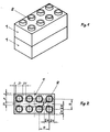
- Fig. 1: eine perspektivische Ansicht von zwei miteinander verbauten Bausteinen;
- Fig. 2: eine Draufsicht auf einen Baustein mit den erfindungsgemäß vergrößerten Primärkupplungselementen;
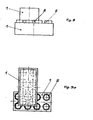
- Fig. 3 zwei rechtwinklig zueinander verbaute Bausteine und 3a: vermittels ihrer Primärkupplungsorgane;
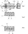
- Fig. 4: die Sekundärkupplungsorgane des Bausteines nach der Erfindung;
- Fig. 5: den Schnitt A-A gemäß Fig. 4;
- Fig. 6: eine Ausführuhgsvariante der Sekundärkupplungeorgane nach der Erfindung;
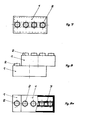
- Fig. 7: einen Baustein mit in der Kitte im halben Teilungsabstand angeordneten Primärkupplungselementen;
- Fig. 8, zwei versetzt verbaute Bausteine in der Aus-8a, führung nach Fig. 7; bis 8c:
- Fig. 9, zwei versetzt verbaute Bausteine, die im halben 9a, Teilungsabstand in mindestens einer Richtung bis 9b: über den Baustein hinaus verbaut sind.
- Der in Fig. 1 bis 3 dargestellte Baustein ist ein vorzugsweise aus Kunststoff hergestellter, kastenförmiger Hohlkörper 1. Dieser Hohlkörper 1 ist an der unteren Seite offen, während auf der geschlossenen oberen Seite Primärkupplungsorgane 2 in Form von kreiszylindrischen Zapfen angeordnet sind.
- Die Außendurchmesser D der Primärkupplungsorgane sind bei gleichzeitiger Reäuzierung der Wandstärke t des kastenförmigen Hohlkörpers so vergrößert worden, daß die auf der geschlossenen Wandung vorhandenen im Raster nebeneinanderliegenden Primärkupplungselemente 2, von denen vier Zapfen die Ecken eines Quadrates darstellen, mit den Primärkupplungselementen 2 eines benachbarten Bausteins versetzt in einem halben Teilungsabstand (halbes Raster) in x und y Richtung in Eingriff gebracht werden können. Im Innern des Hohlkörpers 1 sind zwei dünnwandige gerade Wände 3 vorgesehen, die als Sekundärkupplungselemente dienen (Fig. 4 und 5). Die Wände 3 verlaufen in Längsachse des Bausteins und sind mit Ausnehmungen 4 zur Aufnahme von Kreisabschnitten (Segmenten) der vorzugsweise in Form von Kreiszylindern ausgebildeten Primärkupplungselementen 2 versehen.
- In Fig. 6 sind die Wände 3 gemäß Ausführungsvariante unterhalb der Ausnehmungen 4 vorzugsweise gerade ausgebildet, während die verbleibenden Stege zwischen den Ausnehmungen 4 eine wellenartige Gestaltung 5 aufweisen.
- Auf Grund der im kastenförmigen Hohlkörper 1 angeordneten Wände 3 mit Ausnehmungen 4 ist, wie in Fig. 7 bis 9 gezeigt, die Anordnung von Primärkupplungselementen 2 mittig im halben Teilungsabstand hintereinanderliegend möglich. Diese Anordnung gestattet die Verbaubarkeit zwischen den, im kastenförmigen Hohlkörper 1 angeordneten Wänden 3 und im halben Teilungsabstand zwischen Außenwand des kastenförmigen Hohlkörpers 1 und einer mit Ausnehmungen 4 versehenen Wand 3, (Fig. 8a bis 9b).
-
- 1 Hohlkörper/Baustein
- 2 Primärkupplungselement
- 3 Wand
- 4 Ausnehmung
- 5 wellenartige Gestaltung
- D Außendurchmesser der Primärkupplungselemente
- t Wandstärke des Hohlkörpers
- R Raster
Claims (4)
Priority Applications (1)
| Application Number | Priority Date | Filing Date | Title |
|---|---|---|---|
| AT85106943T ATE52933T1 (de) | 1984-06-04 | 1985-06-04 | Baustein. |
Applications Claiming Priority (2)
| Application Number | Priority Date | Filing Date | Title |
|---|---|---|---|
| DD84263791A DD229036B1 (de) | 1984-06-04 | 1984-06-04 | Baustein |
| DD263791 | 1984-06-04 |
Publications (2)
| Publication Number | Publication Date |
|---|---|
| EP0204016A1 true EP0204016A1 (de) | 1986-12-10 |
| EP0204016B1 EP0204016B1 (de) | 1990-05-23 |
Family
ID=5557648
Family Applications (1)
| Application Number | Title | Priority Date | Filing Date |
|---|---|---|---|
| EP85106943A Expired - Lifetime EP0204016B1 (de) | 1984-06-04 | 1985-06-04 | Baustein |
Country Status (6)
| Country | Link |
|---|---|
| EP (1) | EP0204016B1 (de) |
| AT (1) | ATE52933T1 (de) |
| DD (1) | DD229036B1 (de) |
| DE (1) | DE3577808D1 (de) |
| FI (1) | FI83732C (de) |
| HU (1) | HU209254B (de) |
Cited By (2)
| Publication number | Priority date | Publication date | Assignee | Title |
|---|---|---|---|---|
| FR2733435A1 (fr) * | 1995-04-28 | 1996-10-31 | Point Cartes | Jeu de construction |
| CN105833541A (zh) * | 2016-04-06 | 2016-08-10 | 苏州乐派特机器人有限公司 | 一种积木拼接结构单元 |
Citations (5)
| Publication number | Priority date | Publication date | Assignee | Title |
|---|---|---|---|---|
| DE1076007B (de) * | 1958-01-28 | 1960-02-18 | Godtfred Kirk Christiansen | Bauelement fuer Bauspielzeuge |
| DE1106222B (de) * | 1957-08-08 | 1961-05-04 | Poul Willumsen | Bauelement zur Herstellung von Modellbauten |
| US3234683A (en) * | 1961-10-19 | 1966-02-15 | Interlego Ag | Toy building element including a rotatable bushing |
| DE2242046A1 (de) * | 1972-08-26 | 1974-02-28 | Lego As | Bauelement fuer bauspielzeuge |
| US3867784A (en) * | 1972-10-07 | 1975-02-25 | Helmut Lange | Toy brick and combination of toy bricks |
-
1984
- 1984-06-04 DD DD84263791A patent/DD229036B1/de not_active IP Right Cessation
-
1985
- 1985-05-06 HU HU851708A patent/HU209254B/hu not_active IP Right Cessation
- 1985-05-22 FI FI852034A patent/FI83732C/fi not_active IP Right Cessation
- 1985-06-04 EP EP85106943A patent/EP0204016B1/de not_active Expired - Lifetime
- 1985-06-04 AT AT85106943T patent/ATE52933T1/de not_active IP Right Cessation
- 1985-06-04 DE DE8585106943T patent/DE3577808D1/de not_active Expired - Fee Related
Patent Citations (5)
| Publication number | Priority date | Publication date | Assignee | Title |
|---|---|---|---|---|
| DE1106222B (de) * | 1957-08-08 | 1961-05-04 | Poul Willumsen | Bauelement zur Herstellung von Modellbauten |
| DE1076007B (de) * | 1958-01-28 | 1960-02-18 | Godtfred Kirk Christiansen | Bauelement fuer Bauspielzeuge |
| US3234683A (en) * | 1961-10-19 | 1966-02-15 | Interlego Ag | Toy building element including a rotatable bushing |
| DE2242046A1 (de) * | 1972-08-26 | 1974-02-28 | Lego As | Bauelement fuer bauspielzeuge |
| US3867784A (en) * | 1972-10-07 | 1975-02-25 | Helmut Lange | Toy brick and combination of toy bricks |
Cited By (2)
| Publication number | Priority date | Publication date | Assignee | Title |
|---|---|---|---|---|
| FR2733435A1 (fr) * | 1995-04-28 | 1996-10-31 | Point Cartes | Jeu de construction |
| CN105833541A (zh) * | 2016-04-06 | 2016-08-10 | 苏州乐派特机器人有限公司 | 一种积木拼接结构单元 |
Also Published As
| Publication number | Publication date |
|---|---|
| HUT40028A (en) | 1986-11-28 |
| DD229036A1 (de) | 1985-10-30 |
| EP0204016B1 (de) | 1990-05-23 |
| HU209254B (en) | 1994-04-28 |
| FI83732C (fi) | 1991-08-26 |
| FI83732B (fi) | 1991-05-15 |
| ATE52933T1 (de) | 1990-06-15 |
| FI852034L (fi) | 1985-12-05 |
| DE3577808D1 (de) | 1990-06-28 |
| FI852034A0 (fi) | 1985-05-22 |
| DD229036B1 (de) | 1988-11-30 |
Similar Documents
| Publication | Publication Date | Title |
|---|---|---|
| DE69837717T2 (de) | Platten für spielbausets | |
| DE3114693A1 (de) | Gestaltungsspielzeug | |
| WO1990006391A1 (de) | Modul mit tuftingwerkzeugen | |
| DE2729691C2 (de) | Kugelförmiger Füllkörper für Destillationssäulen und Vorrichtung zu dessen Herstellung | |
| DE212015000291U1 (de) | Sechsflächiger Eisendraht-Aktivitätswürfel | |
| DE2446475B2 (de) | Spielzeug-Steckbaustein | |
| DE2230055A1 (de) | Bausatz zum zusammensetzen von abteilungswaenden, regalwangen, zaeunen, gittern oder dergleichen | |
| DE102007058785B3 (de) | Zusammensteckbare Entwässerungs- und/oder Drainagevorrichtung | |
| EP0204016B1 (de) | Baustein | |
| AT396856B (de) | Behälter für eine kassette | |
| EP0352512B1 (de) | Abstandshalter | |
| DE3420630C2 (de) | ||
| DE8511117U1 (de) | Behälter mit einem Einsatzkörper zum Festlegen von länglichen Gegenständen | |
| CH687677A5 (de) | Bausatz zur Herstellung eines Spielzeugwuerfels. | |
| DE1076007B (de) | Bauelement fuer Bauspielzeuge | |
| EP1938904A1 (de) | Stützvorrichtung für die Abdeckung der Wanne eines Spring- oder Zierbrunnens | |
| DE8603643U1 (de) | Bauelemente zur Verwendung im Bauwesen und als Spielzeug | |
| DE202019104863U1 (de) | Unterlegscheibe zum Ausgleich von Unterlagenunebenheiten bei Montagen sowie Bausatz bestehend aus mehreren solcher Unterlegscheiben | |
| EP0008681A1 (de) | Farbbandkassette | |
| DE2102284A1 (de) | Losbare Steckverbindung | |
| DE202024103451U1 (de) | Modulares Spielzeugsystem mit Spielzeugbogenbauelement | |
| DE8228747U1 (de) | Rost zur begehbaren abdeckung von rinnen, becken, gruben oder als fussabtreter | |
| DE3802320C1 (de) | ||
| DE4411329A1 (de) | Steckbaustein | |
| DE3222333A1 (de) | Videokassettenbehaelter |
Legal Events
| Date | Code | Title | Description |
|---|---|---|---|
| PUAI | Public reference made under article 153(3) epc to a published international application that has entered the european phase |
Free format text: ORIGINAL CODE: 0009012 |
|
| AK | Designated contracting states |
Kind code of ref document: A1 Designated state(s): AT BE CH DE FR GB IT LI NL SE |
|
| 17P | Request for examination filed |
Effective date: 19870219 |
|
| 17Q | First examination report despatched |
Effective date: 19870914 |
|
| GRAA | (expected) grant |
Free format text: ORIGINAL CODE: 0009210 |
|
| AK | Designated contracting states |
Kind code of ref document: B1 Designated state(s): AT BE CH DE FR GB IT LI NL SE |
|
| PG25 | Lapsed in a contracting state [announced via postgrant information from national office to epo] |
Ref country code: IT Free format text: LAPSE BECAUSE OF FAILURE TO SUBMIT A TRANSLATION OF THE DESCRIPTION OR TO PAY THE FEE WITHIN THE PRESCRIBED TIME-LIMIT;WARNING: LAPSES OF ITALIAN PATENTS WITH EFFECTIVE DATE BEFORE 2007 MAY HAVE OCCURRED AT ANY TIME BEFORE 2007. THE CORRECT EFFECTIVE DATE MAY BE DIFFERENT FROM THE ONE RECORDED. Effective date: 19900523 |
|
| REF | Corresponds to: |
Ref document number: 52933 Country of ref document: AT Date of ref document: 19900615 Kind code of ref document: T |
|
| PGFP | Annual fee paid to national office [announced via postgrant information from national office to epo] |
Ref country code: BE Payment date: 19900621 Year of fee payment: 6 |
|
| REF | Corresponds to: |
Ref document number: 3577808 Country of ref document: DE Date of ref document: 19900628 |
|
| PG25 | Lapsed in a contracting state [announced via postgrant information from national office to epo] |
Ref country code: LI Effective date: 19900630 Ref country code: CH Effective date: 19900630 |
|
| ET | Fr: translation filed | ||
| GBT | Gb: translation of ep patent filed (gb section 77(6)(a)/1977) | ||
| REG | Reference to a national code |
Ref country code: CH Ref legal event code: PL |
|
| PLBE | No opposition filed within time limit |
Free format text: ORIGINAL CODE: 0009261 |
|
| STAA | Information on the status of an ep patent application or granted ep patent |
Free format text: STATUS: NO OPPOSITION FILED WITHIN TIME LIMIT |
|
| 26N | No opposition filed | ||
| PG25 | Lapsed in a contracting state [announced via postgrant information from national office to epo] |
Ref country code: BE Effective date: 19910630 |
|
| BERE | Be: lapsed |
Owner name: VEB PLASTICA PLASTSPIELWAREN UND PLASTERZEUGNISSE Effective date: 19910630 |
|
| PGFP | Annual fee paid to national office [announced via postgrant information from national office to epo] |
Ref country code: SE Payment date: 19930510 Year of fee payment: 9 |
|
| PG25 | Lapsed in a contracting state [announced via postgrant information from national office to epo] |
Ref country code: SE Effective date: 19940605 |
|
| EUG | Se: european patent has lapsed |
Ref document number: 85106943.5 Effective date: 19950110 |
|
| EUG | Se: european patent has lapsed |
Ref document number: 85106943.5 |
|
| PGFP | Annual fee paid to national office [announced via postgrant information from national office to epo] |
Ref country code: GB Payment date: 19960626 Year of fee payment: 12 |
|
| PGFP | Annual fee paid to national office [announced via postgrant information from national office to epo] |
Ref country code: FR Payment date: 19960628 Year of fee payment: 12 |
|
| PGFP | Annual fee paid to national office [announced via postgrant information from national office to epo] |
Ref country code: NL Payment date: 19960630 Year of fee payment: 12 Ref country code: AT Payment date: 19960630 Year of fee payment: 12 |
|
| PGFP | Annual fee paid to national office [announced via postgrant information from national office to epo] |
Ref country code: DE Payment date: 19960705 Year of fee payment: 12 |
|
| PG25 | Lapsed in a contracting state [announced via postgrant information from national office to epo] |
Ref country code: GB Free format text: LAPSE BECAUSE OF NON-PAYMENT OF DUE FEES Effective date: 19970604 Ref country code: AT Effective date: 19970604 |
|
| PG25 | Lapsed in a contracting state [announced via postgrant information from national office to epo] |
Ref country code: NL Effective date: 19980101 |
|
| GBPC | Gb: european patent ceased through non-payment of renewal fee |
Effective date: 19970604 |
|
| PG25 | Lapsed in a contracting state [announced via postgrant information from national office to epo] |
Ref country code: FR Free format text: LAPSE BECAUSE OF NON-PAYMENT OF DUE FEES Effective date: 19980227 |
|
| NLV4 | Nl: lapsed or anulled due to non-payment of the annual fee |
Effective date: 19980101 |
|
| PG25 | Lapsed in a contracting state [announced via postgrant information from national office to epo] |
Ref country code: DE Free format text: LAPSE BECAUSE OF NON-PAYMENT OF DUE FEES Effective date: 19980303 |
|
| REG | Reference to a national code |
Ref country code: FR Ref legal event code: ST |
|
| REG | Reference to a national code |
Ref country code: FR Ref legal event code: ST |