EP0204018B1 - Stanzpresse - Google Patents
Stanzpresse Download PDFInfo
- Publication number
- EP0204018B1 EP0204018B1 EP85107002A EP85107002A EP0204018B1 EP 0204018 B1 EP0204018 B1 EP 0204018B1 EP 85107002 A EP85107002 A EP 85107002A EP 85107002 A EP85107002 A EP 85107002A EP 0204018 B1 EP0204018 B1 EP 0204018B1
- Authority
- EP
- European Patent Office
- Prior art keywords
- carriage
- stamping
- punch
- stamping machine
- fact
- Prior art date
- Legal status (The legal status is an assumption and is not a legal conclusion. Google has not performed a legal analysis and makes no representation as to the accuracy of the status listed.)
- Expired
Links
- 239000000463 material Substances 0.000 claims abstract description 54
- 230000033001 locomotion Effects 0.000 claims abstract description 32
- 230000004888 barrier function Effects 0.000 claims abstract description 5
- 239000011248 coating agent Substances 0.000 claims description 2
- 238000000576 coating method Methods 0.000 claims description 2
- 230000000452 restraining effect Effects 0.000 claims description 2
- 230000007246 mechanism Effects 0.000 abstract description 17
- 238000000034 method Methods 0.000 abstract description 4
- 230000008569 process Effects 0.000 abstract description 2
- 238000004080 punching Methods 0.000 abstract 2
- 238000010586 diagram Methods 0.000 description 5
- 125000004122 cyclic group Chemical group 0.000 description 4
- 210000003414 extremity Anatomy 0.000 description 4
- 238000004519 manufacturing process Methods 0.000 description 4
- 230000002441 reversible effect Effects 0.000 description 4
- 230000009471 action Effects 0.000 description 3
- 230000000694 effects Effects 0.000 description 3
- 238000013459 approach Methods 0.000 description 2
- 230000000670 limiting effect Effects 0.000 description 2
- 238000010348 incorporation Methods 0.000 description 1
- 230000002452 interceptive effect Effects 0.000 description 1
- 210000003141 lower extremity Anatomy 0.000 description 1
- 238000012986 modification Methods 0.000 description 1
- 230000004048 modification Effects 0.000 description 1
- 230000036961 partial effect Effects 0.000 description 1
- 230000002829 reductive effect Effects 0.000 description 1
- 230000003252 repetitive effect Effects 0.000 description 1
- 230000035939 shock Effects 0.000 description 1
- 230000032258 transport Effects 0.000 description 1
- 210000001364 upper extremity Anatomy 0.000 description 1
- 230000003245 working effect Effects 0.000 description 1
Images



Classifications
-
- B—PERFORMING OPERATIONS; TRANSPORTING
- B21—MECHANICAL METAL-WORKING WITHOUT ESSENTIALLY REMOVING MATERIAL; PUNCHING METAL
- B21D—WORKING OR PROCESSING OF SHEET METAL OR METAL TUBES, RODS OR PROFILES WITHOUT ESSENTIALLY REMOVING MATERIAL; PUNCHING METAL
- B21D43/00—Feeding, positioning or storing devices combined with, or arranged in, or specially adapted for use in connection with, apparatus for working or processing sheet metal, metal tubes or metal profiles; Associations therewith of cutting devices
- B21D43/02—Advancing work in relation to the stroke of the die or tool
- B21D43/028—Tools travelling with material, e.g. flying punching machines
Definitions
- This invention relates to a stamping machine and in particular is directed to a stamping machine devoid of material feeding accessories, stamping and/or forming dies and material piloting devices, while yet achieving high production speeds and accuracy in pitch, form and quality.
- stamping machines use hitch type feeds which advance the material to be stamped and/or formed through one or a series of dies mounted in a stamping press, the finished product then being collected after discharge from the stamping operation after being acted upon by the die or dies.
- the stamping press hits in a repetitive up-down motion, closing and opening the die in one positive movement every short fraction of the stamping press cycle, the material then, with the die open, being advanced one pitch into its next dormant position, ready to receive the next closing and opening sequence of the die by the said roll or hitch feeding machine.
- AU-A-117,045 discloses an apparatus for stamping material according to the pre-characterising part of claim 1 in which a carriage carrying a punch and die apparatus is reciprocally actuated in a predetermined time sequence by power driving means and the punch is disposed to engage the material during stamping and to thereafter move the material while so engaged a distance determined by the power driving means.
- Stamping means coupled to the power means actuate the punch according to the predetermined time sequence and means are provided for clamping and releasing the material in the time sequence.
- the present invention provides a strip material stamping machine comprising
- a further object of the invention is to provide a stamping machine which can run at very high speeds and considerable accuracy; is simple and economical, to operate; is rugged, durable and contains relatively fewer moving parts to maintain and adjust.
- Figures 1-3 diagrams illustrating a carriage 1 bearing die 2 and reciprocated by a crank arrangement 3, motor driven' the hub of which is equipped with an eccentric 4 which dimensionally provides for the desired pitch plus a dwell period at each end of the carriage travel.
- the dwell period is timed to the dwell provided by the stamping components of the machine.
- heavy blocks 5 and 5a are affixed to the rails 6 on which said carriage travels. The carriage travels within the limits of these blocks upon its back and forth movement.
- This dimension, adjustable, is the desired pitch dimension and must never exceed the full stroke of the crank less a certain minimum dimension providing for the necessary dwell periods utilized by the die performing its function properly.
- This arrangement actually causes the carriage to impact with a block at each end of its back and forth movement. This means that the accuracy of the pitch is established by the carriage being brought firmly and positively into contact with the blocks, the distance therebetween being called the pitch.
- the carriage 1 approaches the block 5 at the end of the stroke period at a reduced speed so that after contact is made the carriage changes direction. Hence at the point of contact the carriage reaches zero speed so that at contact the noise level should be minimal. It is also possible to reduce noise at the point of contact by coating the block and carrier at their interfacing surfaces 5a, 6a with material designed to reduce noise to low tolerable levels.
- a crank 5' attached to the eccentric 4, imparts reciprocating motion to the carriage by means of an impellor 7 which consists of a push rod 8 equipped at both ends (designed to function in each direction of the carriage travel) with buffer springs 9. These springs are sufficiently stiff to propel the carriage into contact with the blocks 5a and 5. After actual contact takes place the continuing stroke of the crank causes the spring to compress, trapping the carriage between it and the block with growing power, until the rotation of the crank reverses the direction of the impellor rod. At this point it must be noted that the carriage (die) is in the dwell period and motionless, until the carriage is brought into its reverse motion by the spring at the opposite end of the impellor rod by the crank eccentric as the first spring loses contact with the carriage. These springs also act as dampeners, lessening the shock of the impact referred to herein.
- the linear speed of the crank-operated impellor 7 is not constant, but diminishes as the crank approaches the end of its stroke to give speed linearly at that exact point where it reverses direction, then accelerates to top speed at the high point of its eccentric, to diminish this speed to a stop at the point in rotation where it must again reverse direction.
- This speed factor is exploited by locating the dwell period at each end of the carriage back and forth movement; just before and just after reversal of travel when linear speed of movement is very low or zero a stop in the period of time when the various activities required by this system are performed, as shown specifically in Figure 1 which depicts the time- movement diagram of the system.
- the die is open (a) on carriage, returning from its mission of delivering stamped material to the discharge point, carriage collides with limiting block and comes to complete stop, clamped in place, as crank proceeds onward to point of reversal of direction; at point of reversal stamping action takes place and punch penetrates material; clamp keeping material in position releases; carriage resumes movement in reverse direction as impellor picks it up, the die remaining closed with its punch through the material acting as a positive clamp, and travels to point of impact and halted; material clamp closed, to lock material securely in position; die opens, completing the stamping operation and freeing itself from the material; carriage reverses direction with die open, and the entire sequence of activity repeats itself.
- Figure 1 shows the timing sequence as a function of the eccentric
- Figure 3 shows physically how the operation may be observed.
- the clamp 15 is closed on material 16 and the die stamp 17 has stamped the material.
- the clamp 15 opens and the die stamp 17 still remains within the material.
- the stamp still within the material transports the material, the extent of the pitch movement 18 of the carriage to which it is attached.
- the clamp 15 closes and the stamp lifts off the material, the clamp holding the material firmly in place.
- the stamp is carried back to the extent of the pitch 18 movement of the carriage in the reverse direction from the place of beginning to complete the cycle.
- a feature of the stamping press is the incorporation of the clamping device operated by the stamping component assembly to assure positive timing.
- This device clamps the material being processed firmly in position except from the moment the die has penetrated the material at which time it assumes the role of the clamp before it (the die) resumes motion.
- the die draws the material to the discharge end of the production cycle, to the position in time when the die is halted by the pitch block, at this point the clamp closes before the die opens to release the material.
- the die may return to its starting position without affecting the positioned material; this procedure guarantees that the material is always clamped tight, by the die closed, by the die and the clamps closed or the clamp closed. Freedom to move is never accorded the material at any time during the production cycle.
- the stamping process one of the reasons for the high accuracy is the stamping process.
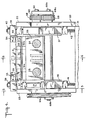
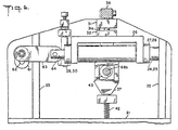
- FIG 4, 5 and 6 various views of such a machine, said machine in particular comprising a frame 20 mounted to a base 21 and having side walls 22 and 23, each fixedly supporting a pair of spaced apart support rods 24 and 25. Intermediate said walls is positioned a channel-shaped carriage mechanism 26 slidably supported by said pair of spaced-apart support rods and having freedom of longitudinal movement along said support rods. Mounted to said support rods and bridging said carriage are pairs of retaining rings 27, 28 and 29, 30 each pair being fixedly mounted to the support rods and spanning the carriage mechanism.
- each bridging pair 27, 29 and 28, 30 less the length of the well portion of the channel-shaped carriage constitutes the pitch or travel of the carriage when undergoing its cyclic movements.
- the facing of the retaining rings represent the barrier or retaining wall against which the carriage impinges, as discussed previously with respect to the operating principles of the invention.
- stamping die apparatus consisting of punch 31 and die 32, each disposed to ride with the carriage during its cyclic movements as a unit or combination thru the facility of slide posts 31a and 32a.
- the punch portion of the stamp die apparatus is activated by the operation of stamping post mechanism 35.
- the stamping post mechanism comprising a pair of vertically positioned stamping parts 36 and 37, each straddling the carriage mechanism 26 and bridged by a support bar 38 to which it is attached by nuts 39 and 40 at the upper extremities thereof.
- the lower extremities of said stamping posts are supported by coil springs 41 and 42 which are in turn attached to the base 21.
- the stamping post is driven in a vertical direction by a cam mechanism 43 so disposed as to provide the cyclic variation previously described with respect to the time sequence of the various functions.
- the cam is so designed as to assure the opening and closing of the punch at the proper time during the sequence of operations of the various units making up the machine.
- the cam is designed to have dwell periods in timed relationship to each end of the crank stroke and is suitably driven by a belt 60a or other linkage mechanism to the driving mechanism 60b powering the eccentric.
- a clamping mechanism 50 for suitably and reliably clamping the material to be stamped is shown in said Figures 4 and 5 and is controlled by a linkage device 51 which has an extremity thereof connected to a clamping post 52 and the other extremity connected to the stamping post 35, both extremities having rotatable rollers attached thereto for positively engaging both the stamping and clamping posts.
- the linkage is pivotally mounted to the frame and is made operable by the controlled time operation of the stamping posts.
- the movements of the stamping die apparatus atop the carriage is further made feasible by the use of hangers 54 and 55 connected to bridging bar 38.
- the punch portion 31 of the stamping mechanism has elongated grooves 56 and 57 along which the hook portions 58, 59 are free to ride.
- the lifting of the punch from the die or material is accomplished by the hangers which are in turn connected to the bridging bar which is in turn connected to and actuated by the stamping posts.
- the movement of the punch and die with the carriage permits the punch portion to slide or move relative to the hangers the length of the pitch movement previously mentioned.
- the punch and die are permitted freedom of movement with the carriage in a horizontal direction while the stamping of bridging-bar remains free to move only in the vertical direction and not horizontally.
- the punch and die move together on the carriage as a unit through the facility of the slidable posts 31 a, 31 b.
- the posts are fixedly attached to the base or die and the punch slidably moves vertically with respect to such posts. This is schematically shown in Fig. 2 and again in Fig. 9.
- Figure 8 shows a system for preventing rebound, to prevent the carriage mechanism from bouncing off the retaining walls when impact takes place and thereby interfering with the accurate positioning of the die and/or material.
- the system comprises a pulley 60 belt driven by a belt 68 and shaft connected to an eccentric 61 via shaft 62.
- the eccentric 61 is coupled to a crank 63 link-connected to an impellor assembly 64 which is in turn connected to carriage 26 previously described.
- the power drive permits the carriage to undergo reciprocal action, also previously described.
- latch 71a rotates in a direction which blocks carriage 26 from moving, and similarly the other latch 71 b when the carriage moves in the other direction performs the same function. Both latches are phased 180 degrees apart to effect the proper function.
- the pulley 60 as stated is drawn by a belt 68 which is connected to pulley wheel 68a connected to shaft 68b.
- the shaft 68b is driven by a relatively, large pulley wheel 69a which is belt connected via belt 69a to an external motor or power source not shown. Also connected to shaft 68b and driven thereby are the stamping post mechanism 35.
- FIG. 7 One form of impellor assembly driven by the eccentric is shown in Figure 7 and comprises an impellor rod 70 surrounded by a barrel 71 exter- - nally threaded at both extremities and threadably engaged by a pair of internally threaded end caps 72 and 73. Intermediate said impellor rod and barrel in proximity to said end caps are a pair of support bearings 74, 75, for substantially completing the impellor assembly, with the exception of a split-collar insert 76.
- the impellor assembly, as shown, with its springs reciprocates slightly within the limits imposed by the inside surfaces of the carriage so that as one spring compresses to force carriage wall against pitch limit in one direction, the other can exert its pressure only on the other inner surface of said carriage.
- Figure 9 shows schematically a system for mounting multiple dies on a single carriage and in general comprises an eccentric drive 80 connected to an impellor assembly 81 which imparts reciprocal motion to a carriage 82 upon which there is attached and movable therewith a plurality of dies 83, 84 and 85 which typically are used for blanking, stamping and forming respectively.
- an eccentric drive 80 connected to an impellor assembly 81 which imparts reciprocal motion to a carriage 82 upon which there is attached and movable therewith a plurality of dies 83, 84 and 85 which typically are used for blanking, stamping and forming respectively.
Landscapes
- Engineering & Computer Science (AREA)
- Mechanical Engineering (AREA)
- Shaping Metal By Deep-Drawing, Or The Like (AREA)
- Perforating, Stamping-Out Or Severing By Means Other Than Cutting (AREA)
- Punching Or Piercing (AREA)
- Press Drives And Press Lines (AREA)
Claims (8)
Priority Applications (4)
| Application Number | Priority Date | Filing Date | Title |
|---|---|---|---|
| US06/568,299 US4535617A (en) | 1984-01-05 | 1984-01-05 | Stamping machine |
| AT85107002T ATE49359T1 (de) | 1985-06-05 | 1985-06-05 | Stanzpresse. |
| EP85107002A EP0204018B1 (de) | 1985-06-05 | 1985-06-05 | Stanzpresse |
| DE8585107002T DE3575268D1 (de) | 1985-06-05 | 1985-06-05 | Stanzpresse. |
Applications Claiming Priority (1)
| Application Number | Priority Date | Filing Date | Title |
|---|---|---|---|
| EP85107002A EP0204018B1 (de) | 1985-06-05 | 1985-06-05 | Stanzpresse |
Publications (2)
| Publication Number | Publication Date |
|---|---|
| EP0204018A1 EP0204018A1 (de) | 1986-12-10 |
| EP0204018B1 true EP0204018B1 (de) | 1990-01-10 |
Family
ID=8193548
Family Applications (1)
| Application Number | Title | Priority Date | Filing Date |
|---|---|---|---|
| EP85107002A Expired EP0204018B1 (de) | 1984-01-05 | 1985-06-05 | Stanzpresse |
Country Status (3)
| Country | Link |
|---|---|
| EP (1) | EP0204018B1 (de) |
| AT (1) | ATE49359T1 (de) |
| DE (1) | DE3575268D1 (de) |
Family Cites Families (3)
| Publication number | Priority date | Publication date | Assignee | Title |
|---|---|---|---|---|
| FR568533A (fr) * | 1923-07-10 | 1924-03-28 | Appareil pour perforer, marquer, graver, comprimer, etc., à intervalles réguliers une bande se déplaçant d'un mouvement uniforme continu | |
| NL126925C (de) * | 1961-12-06 | 1900-01-01 | ||
| JPS551986A (en) * | 1979-04-11 | 1980-01-09 | Daido Kogyo Co Ltd | Synchronous type continuous processing appratus |
-
1985
- 1985-06-05 AT AT85107002T patent/ATE49359T1/de not_active IP Right Cessation
- 1985-06-05 EP EP85107002A patent/EP0204018B1/de not_active Expired
- 1985-06-05 DE DE8585107002T patent/DE3575268D1/de not_active Expired - Fee Related
Also Published As
| Publication number | Publication date |
|---|---|
| DE3575268D1 (de) | 1990-02-15 |
| EP0204018A1 (de) | 1986-12-10 |
| ATE49359T1 (de) | 1990-01-15 |
Similar Documents
| Publication | Publication Date | Title |
|---|---|---|
| CN1067630C (zh) | 往复式冲压驱动装置 | |
| US4345452A (en) | Cam shaft operated punch press for expanding lead alloy battery grid material | |
| EP0391747B1 (de) | Einschneidiger Stanzblock | |
| US3289453A (en) | Apparatus for manufacturing container bodies from blanks | |
| US4018328A (en) | Means for producing a dual acceleration-deceleration movement for a transfer shuttle | |
| US4535617A (en) | Stamping machine | |
| EP0204018A1 (de) | Stanzpresse | |
| US4513600A (en) | Cam actuated ejector for a shell press | |
| US3538735A (en) | Multiple side punching machine | |
| GB1460986A (en) | Rotary crank press | |
| US4019432A (en) | Rivet making machine | |
| CN111672966A (zh) | 一种工件双侧同步冲孔方法 | |
| KR910009858B1 (ko) | 스탬핑 기계 | |
| US3948298A (en) | Automatic lead straightening of axial leaded components | |
| US3919876A (en) | Toggle press | |
| CN215544394U (zh) | 一种车用挡圈冲压装置 | |
| US4048838A (en) | Arrangement for controllably reciprocating a workpiece gripping assembly of a multi-stage press | |
| US5110026A (en) | Apparatus for a stepwise advancing of a web-shaped workpiece | |
| US7111766B2 (en) | Apparatus for and a method of an intermittent feeding of a strip shaped blank to a press | |
| US3371514A (en) | Indexing apparatus | |
| JPH0220335B2 (de) | ||
| US4627264A (en) | Cam actuated ejector for a shell press | |
| US3898903A (en) | Trimming machines | |
| CN216632430U (zh) | 一种金属丝成型装置 | |
| US4052763A (en) | Rivet making method |
Legal Events
| Date | Code | Title | Description |
|---|---|---|---|
| PUAI | Public reference made under article 153(3) epc to a published international application that has entered the european phase |
Free format text: ORIGINAL CODE: 0009012 |
|
| AK | Designated contracting states |
Kind code of ref document: A1 Designated state(s): AT BE CH DE FR GB IT LI NL |
|
| 17P | Request for examination filed |
Effective date: 19870514 |
|
| 17Q | First examination report despatched |
Effective date: 19880601 |
|
| RAP1 | Party data changed (applicant data changed or rights of an application transferred) |
Owner name: SEQUINS INTERNATIONAL INC. |
|
| GRAA | (expected) grant |
Free format text: ORIGINAL CODE: 0009210 |
|
| AK | Designated contracting states |
Kind code of ref document: B1 Designated state(s): AT BE CH DE FR GB IT LI NL |
|
| PG25 | Lapsed in a contracting state [announced via postgrant information from national office to epo] |
Ref country code: NL Effective date: 19900110 Ref country code: FR Effective date: 19900110 Ref country code: BE Effective date: 19900110 |
|
| REF | Corresponds to: |
Ref document number: 49359 Country of ref document: AT Date of ref document: 19900115 Kind code of ref document: T |
|
| REF | Corresponds to: |
Ref document number: 3575268 Country of ref document: DE Date of ref document: 19900215 |
|
| ITF | It: translation for a ep patent filed | ||
| EN | Fr: translation not filed | ||
| NLV1 | Nl: lapsed or annulled due to failure to fulfill the requirements of art. 29p and 29m of the patents act | ||
| PLBE | No opposition filed within time limit |
Free format text: ORIGINAL CODE: 0009261 |
|
| STAA | Information on the status of an ep patent application or granted ep patent |
Free format text: STATUS: NO OPPOSITION FILED WITHIN TIME LIMIT |
|
| 26N | No opposition filed | ||
| ITTA | It: last paid annual fee | ||
| PGFP | Annual fee paid to national office [announced via postgrant information from national office to epo] |
Ref country code: GB Payment date: 19920519 Year of fee payment: 8 |
|
| PGFP | Annual fee paid to national office [announced via postgrant information from national office to epo] |
Ref country code: DE Payment date: 19920603 Year of fee payment: 8 Ref country code: CH Payment date: 19920603 Year of fee payment: 8 |
|
| PGFP | Annual fee paid to national office [announced via postgrant information from national office to epo] |
Ref country code: AT Payment date: 19920615 Year of fee payment: 8 |
|
| PG25 | Lapsed in a contracting state [announced via postgrant information from national office to epo] |
Ref country code: GB Effective date: 19930605 Ref country code: AT Effective date: 19930605 |
|
| PG25 | Lapsed in a contracting state [announced via postgrant information from national office to epo] |
Ref country code: LI Effective date: 19930630 Ref country code: CH Effective date: 19930630 |
|
| GBPC | Gb: european patent ceased through non-payment of renewal fee |
Effective date: 19930605 |
|
| REG | Reference to a national code |
Ref country code: CH Ref legal event code: PL |
|
| PG25 | Lapsed in a contracting state [announced via postgrant information from national office to epo] |
Ref country code: DE Effective date: 19940301 |