EP0204149A2 - Rührorgan - Google Patents
Rührorgan Download PDFInfo
- Publication number
- EP0204149A2 EP0204149A2 EP86105991A EP86105991A EP0204149A2 EP 0204149 A2 EP0204149 A2 EP 0204149A2 EP 86105991 A EP86105991 A EP 86105991A EP 86105991 A EP86105991 A EP 86105991A EP 0204149 A2 EP0204149 A2 EP 0204149A2
- Authority
- EP
- European Patent Office
- Prior art keywords
- stirrer
- hub
- arm
- stub
- agitator
- Prior art date
- Legal status (The legal status is an assumption and is not a legal conclusion. Google has not performed a legal analysis and makes no representation as to the accuracy of the status listed.)
- Granted
Links
Images


Classifications
-
- B—PERFORMING OPERATIONS; TRANSPORTING
- B01—PHYSICAL OR CHEMICAL PROCESSES OR APPARATUS IN GENERAL
- B01F—MIXING, e.g. DISSOLVING, EMULSIFYING OR DISPERSING
- B01F27/00—Mixers with rotary stirring devices in fixed receptacles; Kneaders
- B01F27/05—Stirrers
- B01F27/07—Stirrers characterised by their mounting on the shaft
- B01F27/071—Fixing of the stirrer to the shaft
-
- B—PERFORMING OPERATIONS; TRANSPORTING
- B01—PHYSICAL OR CHEMICAL PROCESSES OR APPARATUS IN GENERAL
- B01F—MIXING, e.g. DISSOLVING, EMULSIFYING OR DISPERSING
- B01F27/00—Mixers with rotary stirring devices in fixed receptacles; Kneaders
- B01F27/05—Stirrers
- B01F27/11—Stirrers characterised by the configuration of the stirrers
- B01F27/112—Stirrers characterised by the configuration of the stirrers with arms, paddles, vanes or blades
- B01F27/1123—Stirrers characterised by the configuration of the stirrers with arms, paddles, vanes or blades sickle-shaped, i.e. curved in at least one direction
Definitions
- the invention relates to an agitator, in particular in the form of an impeller, consisting of an agitator hub with a plurality of agitator arms for attachment to the agitator shaft for the mixing of substances in agitating vessels, in particular those which tend to caking, encrusting and / or polymerizing.
- Stirrers are used for the exchange of materials in fluid media, which can change from the liquid to the disperse or pasty state.
- Stirring elements of various shapes are known. So there are z. B. stirring elements in anchor form, impeller form, according to DIN 28144, page 13, and in propeller form. Depending on the design of the stirring elements, whether enamelled or bare, and the size of the stirring vessels, the stirring elements can be in one piece or must be in several parts. This in turn depends on the permissible or economical diameter of the mixing vessel lid.
- a one-piece stirring element can always be installed in a mixing vessel with a vessel lid diameter equal to the vessel diameter. If the agitator used, enamelled or bare, has a reduced diameter, the assembly opening, ie the vessel lid, can also be reduced in relation to the vessel diameter. This reduction in the lid diameter is sufficient However, in some processes it is not yet sufficient, so that ultimately a mounting cover diameter is selected which requires a multi-part stirring element.
- the invention relates essentially to such a multi-part stirring element in bare design and in impeller form.
- This stirrer can be divided, i.e. H. disassembled, brought through a relatively small assembly opening into the mixing vessel and assembled there and on the stirrer shaft.
- Multi-part, at least two-part stirring elements are known, in particular in the form of an impeller.
- the invention has for its object to design a multi-part agitator for a mixing vessel with a small assembly opening so that it is free of gaps after installation.
- the advantages achieved by the invention consist in particular in the absence of any gaps on the fully installed multi-part stirring element in the mixing vessel with a small assembly opening. As a result, caking, incrustation and / or polymerisation no longer occur. Routine cleaning ensures complete freedom from residues. Because such mixing vessels for batches production residues could reduce the quality of the next batch. For the first time, mixing vessels with a reduced diameter for the assembly or cleaning opening can be produced, which are intended for the installation of multi-part stirring elements.
- the agitator 1 shown in Fig. 1 consists essentially of the agitator hub 2, which can be attached and attached to an agitator shaft, not shown, in a known manner. From this Rrockernabe 2, the stirrer arms 3 extend in 120 0 division outward. Two of these stirrer arms 3 are always connected to the stirrer hub. The third stirrer arm is reproducibly mountable and detachably attached to the stirrer hub 2 according to the invention.
- the stirrer arm 3, which according to FIG. 2 consists of the two stirrer arm bars 4 and according to FIG. 3, the two stirrer arm webs 5, was divided into the stirrer arm stub 6 and the stirrer arm rest 3 '.
- the stirrer arm stub 6 is rigidly attached to the stirrer hub by means of a permanent weld.
- the stirrer hub 2 with the rigidly connected two stirrer arms is inserted through the assembly opening into the stirrer and fastened to the stirrer shaft without a gap.
- the cap 10 which is similar to a cap, is welded to the stirrer hub 2 without gaps and polished smooth
- the rest of the stirrer arm 3 ' is inserted into the stirrer arm stub 6 after it has been introduced into the stirrer vessel and the gap between the two parts is welded in a positive and non-positive manner, followed by grinding and polishing of the weld seam, so that a completely smooth surface is obtained.
- the weld seam is cut exactly to the line.
- the agitator hub 2 is optionally designed in a known manner for the non-positive connection to the agitator shaft.
- the lower part of the agitator hub can also be designed so that it protects the mechanical seal underneath as a rinsing attachment.
Landscapes
- Chemical & Material Sciences (AREA)
- Chemical Kinetics & Catalysis (AREA)
- Mixers Of The Rotary Stirring Type (AREA)
- Accessories For Mixers (AREA)
- Saccharide Compounds (AREA)
Abstract
Description
- Die Erfindung betrifft ein Rührorgan, insbesondere in Impellerform, bestehend aus Rührernabe mit einer Mehrzahl von Rührerarmen zur Befestigung an der Rührerwelle für die Durchmischung von Substanzen in Rührgefäßen, insbesondere solchen, die zu Anbackungen, Verkrustungen und/oder Anpolymerisation neigen. Rührer dienen dem Stoffaustausch in fluiden Medien, die vom flüssigen auch in den dispersen oder pastösen Zustand übergehen können.
- Es ist erforderlich, daß es am Rührorgan nicht zu Anbackungen, Verkrustungen und/oder zu Anpolymerisationen kommt, weil dadurch seine störungsfreie Funktion als Mischorgan eingeschränkt wird. Bei routinemäßigen Reinigungen sollte-eine rückstandsfreie Reinigung möglich sein, d. h. Spalte zwischen Bauteilen des Rührorgans sollten weitgehend vermieden werden.
- Bekannt sind Rührorgane der verschiedensten Form. So gibt es z. B. Rührorgane in Ankerform, Impellerform, gemäß DIN 28144, Seite 13, und in Propellerform. Je nach Ausführung der Rührorgane, ob emailliert oder blank, und Größe der Rührgefäße können die Rührorgane einteilig oder müssen sie mehrteilig sein. Dies ist wiederum abhängig von dem zulässigen bzw. wirtschaftlichen Durchmesser des Rührgefäßdeckels. In ein Rührgefäß mit einem Gefäßdeckeldurchmesser gleich dem Gefäßdurchmesser kann stets ein einteiliges Rührorgan eingebaut werden. Weist das verwendete Rührorgan, emailliert oder blank einen reduzierten Durchmesser auf, kann auch die Montageöffnung, d. h. der Gefäßdeckel, reduziert werden in Bezug auf den Gefäßdurchmesser. Diese Reduzierung des Deckeldurchmessers reicht jedoch bei manchen Prozessen noch nicht aus, so daß letztendlich ein Montagedeckeldurchmesser gewählt wird, der ein mehrteiliges Rührorgan erforderlich macht.
- Die Erfindung bezieht sich im wesentlichen auf solch ein mehrteiliges Rührorgan in blanker Ausführung und in Impellerform. Dieses Rührorgan kann geteilt, d. h. demontiert, durch eine verhältnismäßig kleine Montageöffnung in das Rührgefäß gebracht und dort zusammen- und an die Rührerwelle montiert werden.
- Bekannt sind mehrteilige, mindestens zweiteilige Rührorgane, insbesondere in Impellerform, wobei z. B. die drei Rührarme als Einarmstück und als Zweiarmstück mit jeweils halbem Nabenteil einzeln durch die kleine Montageöffnung in das Rührgefäß eingebracht werden und dann an der Rührerwelle verschraubt werden. Dabei erhält-man eine Vielzahl von scharfen Kanten an und eine Vielzahl von Spalten zwischen den einzelnen Bauteilen. Die scharfen Kanten und Spalten sind Ausgangspunkt für Anbackungen, Verkrustungen und/oder Anpolymerisation von fluiden Medien.
- Der Erfindung liegt die Aufgabe zugrunde, ein mehrteiliges Rührorgan für ein Rührgefäß mit kleiner Montageöffnung so zu gestalten, daß es nach dem Einbau spaltfrei vorliegt.
- Diese Aufgabe wird gelöst durch die konstruktive Gestaltung des Rührorgans gemäß dem Kennzeichen des Hauptpatentanspruchs. Vorteilhafte Ausführungen des Rührorgans sind gemäß den Kennzeichen der Unteransprüche ausgebildet.
- Die mit der Erfindung erzielten Vorteile bestehen insbesondere im Fehlen jeglicher Spalte am fertig eingebauten mehrteiligen Rührorgans im Rührgefäß mit kleiner Montageöffnung. Dadurch kommt es nicht mehr zu Anbackungen, Verkrustungen und/oder Anpolymerisation. Routinemäßige Reinigungen gewährleisten vollkommene Rückstandsfreiheit. Da solche Rührgefäße für-Chargenbetrieb vorgesehen sind, könnten Produktionsrückstände sich qualitätsmindernd auf die nächste Charge auswirken. Es lassen sich erstmals Rührgefäße mit vermindertem Durchmesser der Montage- bzw. Reinigungsöffnung herstellen, die für den Einbau von mehrteiligen Rührorganen vorgesehen sind.
- Ein Ausführungsbeispiel der Erfindung ist in den Zeichnungen dargestellt und wird im folgenden näher beschrieben. Es zeigen:
- Fig. 1: Rührorgan in Impellerform in der Draufsicht
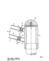
- Fig. 2: Schnitt von Rührernabe und Rührerarm, Schnittlinie A-A aus Fig. 1
- Fig. 3: Schnitt von Rührerarm, Schnittlinie B-B aus Fig. 2
- Das in Fig. 1 dargestellte Rührorgan 1 besteht im wesentlichen aus der Rührernabe 2, die auf eine nicht dargestellte Rührerwelle in bekannter Weise angesetzt und befestigt werden kann. Von dieser Rührernabe 2 erstrecken sich die Rührerarme 3 in 120 0 Teilung nach außen. Zwei dieser Rührerarme 3 sind stets mit der Rührernabe verbunden. Der dritte Rührerarm ist gemäß der Erfindung reproduzierbar montierbar und demontierbar an der Rührernabe 2 befestigt. Dazu wurde der Rührerarm 3, der gemäß Fig. 2 aus den beiden Rührerarmholmen 4 und gemäß Fig. 3 den beiden Rührerarmstegen 5 besteht, in den Rührerarmstummel 6 und den Rührerarmrest 3' geteilt. Der Rührerarmstummel 6 ist mittels einer Dauerschweißnaht starr an die Rührernabe angesetzt. In den beiden zylindrischen Rührerarmholmen 4 des Rührerarmstummels sind Zentriermittelhälften 7, z. B. Zentrierbuchsen eingesetzt und über Positionsschweißpunkte 8 arretiert. Der Rührarmrest 3' erhält in den Rührerarmholmen 4 die Gegenpart-Zentriermittelhälften 7', z. B. Zentrierbuchsen mit ebenfalls Positionsschweißpunkten 8.
- Rührerarmstummel 6 und Rührerarmrest 3' sind über die Zentrierbolzen 9 in den Zentrierbuchsen 7 bzw. 7' zueinander positioniert.
- Für den Einbau des Rührorgans 1 in das Rührgefäß wird die Rührernabe 2 mit den starr verbundenen beiden Rührerarmen durch die Montageöffnung in"das Rührgefäß eingeführt und spaltfrei an der Rührerwelle befestigt. Die kalottenähnliche Kappe 10 wird spaltfrei mit der Rührernabe 2 verschweißt und glatt poliert. Der Rührerarmrest 3' wird nach Einführung in das Rührgefäß auf den Rührerarmstummel 6 aufgesteckt und der Spalt zwischen beiden Teilen wird form- und kraftschlüssig verschweißt. Anschließend erfolgt Abschleifen und Polieren der Schweißnaht, so daß eine vollkommen glatte Fläche erhalten wird.
- Für einen evtl. Ausbau.des Rührorgans wird die Schweißnaht liniengenau aufgetrennt.
- Die Rührernabe 2 ist zur kraftschlüssigen Verbindung mit der Rührerwelle wahlfrei in bekannter Art ausgebildet. Der untere Teil der Rührernabe kann ergänzend so gestaltet sein, daß dieser als Spülvorsatz die unterhalb liegende Gleitringdichtung schützt.
Claims (4)
Priority Applications (1)
| Application Number | Priority Date | Filing Date | Title |
|---|---|---|---|
| AT86105991T ATE46093T1 (de) | 1985-06-01 | 1986-04-30 | Ruehrorgan. |
Applications Claiming Priority (2)
| Application Number | Priority Date | Filing Date | Title |
|---|---|---|---|
| DE3519647 | 1985-06-01 | ||
| DE19853519647 DE3519647A1 (de) | 1985-06-01 | 1985-06-01 | Ruehrorgan |
Publications (3)
| Publication Number | Publication Date |
|---|---|
| EP0204149A2 true EP0204149A2 (de) | 1986-12-10 |
| EP0204149A3 EP0204149A3 (en) | 1987-08-05 |
| EP0204149B1 EP0204149B1 (de) | 1989-09-06 |
Family
ID=6272167
Family Applications (1)
| Application Number | Title | Priority Date | Filing Date |
|---|---|---|---|
| EP86105991A Expired EP0204149B1 (de) | 1985-06-01 | 1986-04-30 | Rührorgan |
Country Status (5)
| Country | Link |
|---|---|
| US (1) | US4720195A (de) |
| EP (1) | EP0204149B1 (de) |
| JP (1) | JPS6211530A (de) |
| AT (1) | ATE46093T1 (de) |
| DE (2) | DE3519647A1 (de) |
Families Citing this family (4)
| Publication number | Priority date | Publication date | Assignee | Title |
|---|---|---|---|---|
| ATE115890T1 (de) * | 1990-01-04 | 1995-01-15 | Bohle L B Pharmatech Gmbh | Mischgranulator. |
| DE4005219A1 (de) * | 1990-02-20 | 1991-08-22 | Bohle L B Pharmatech Gmbh | Ruehrwerk fuer mischgranulatoren |
| JP4754522B2 (ja) * | 2007-04-09 | 2011-08-24 | 西島株式会社 | 切断装置 |
| EP3213811B1 (de) * | 2016-03-01 | 2022-10-12 | Sulzer Management AG | Schaufel für ein laufrad eines rührers, laufrad und rührer |
Family Cites Families (15)
| Publication number | Priority date | Publication date | Assignee | Title |
|---|---|---|---|---|
| US426215A (en) * | 1890-04-22 | Heating and lighting device | ||
| US69248A (en) * | 1867-09-24 | Franklin ransom | ||
| US1400216A (en) * | 1919-04-23 | 1921-12-13 | Wilson & Co Inc | Apparatus for manufacturing shortening material |
| US2298899A (en) * | 1939-02-03 | 1942-10-13 | John Ernest Neale | Interfitting machine and like part |
| DE719434C (de) * | 1940-03-07 | 1942-04-09 | Julius Roemheld Fa | Ruehrfluegelkupplung |
| DE1075560B (de) * | 1957-10-17 | 1960-02-18 | Pfaudier-Werke A.G., Schwetzingen (Bad.) | Rührvorrichtung, die aus mehreren Einzelbauteilen mittels Verbindungsgliedern, wie Schrauben, Muttern, zusammengebaut ist |
| DE2063016A1 (de) * | 1970-12-22 | 1972-08-03 | Kupka D | Rührorgan für Rührwerkskessel |
| NL7301838A (de) * | 1973-02-09 | 1974-08-13 | ||
| DK143497C (da) * | 1976-02-26 | 1982-03-01 | Gram Brdr As | Apparat til udlevering af kornet materiale |
| DE2801460A1 (de) * | 1978-01-13 | 1979-07-19 | Loedige Maschbau Gmbh Geb | Mischmaschine mit keilfoermigen oder pflugscharartigen mischwerkzeugen |
| DE2943713C2 (de) * | 1979-10-30 | 1985-01-10 | Karl Dipl.-Ing. 7000 Stuttgart Schlecht | Halterung für Mischarme |
| JPS6017222Y2 (ja) * | 1980-11-07 | 1985-05-27 | 梶原工業株式会社 | 食品撹拌装置の撹拌羽根取付装置 |
| US4456382A (en) * | 1983-02-03 | 1984-06-26 | The B. F. Goodrich Company | Agitator hub |
| US4491421A (en) * | 1983-11-21 | 1985-01-01 | De Dietrich (Usa), Inc. | Impeller assembly and shaft having interference fit |
| IT8421119U1 (it) * | 1984-03-06 | 1985-09-06 | Cipelletti Alberto | Gelatiera famigliare. |
-
1985
- 1985-06-01 DE DE19853519647 patent/DE3519647A1/de not_active Withdrawn
-
1986
- 1986-04-30 EP EP86105991A patent/EP0204149B1/de not_active Expired
- 1986-04-30 AT AT86105991T patent/ATE46093T1/de active
- 1986-04-30 DE DE8686105991T patent/DE3665414D1/de not_active Expired
- 1986-05-30 JP JP61123846A patent/JPS6211530A/ja active Granted
- 1986-05-30 US US06/868,943 patent/US4720195A/en not_active Expired - Lifetime
Also Published As
| Publication number | Publication date |
|---|---|
| JPH0419895B2 (de) | 1992-03-31 |
| EP0204149B1 (de) | 1989-09-06 |
| ATE46093T1 (de) | 1989-09-15 |
| DE3519647A1 (de) | 1986-12-04 |
| JPS6211530A (ja) | 1987-01-20 |
| EP0204149A3 (en) | 1987-08-05 |
| DE3665414D1 (en) | 1989-10-12 |
| US4720195A (en) | 1988-01-19 |
Similar Documents
| Publication | Publication Date | Title |
|---|---|---|
| EP0785742B1 (de) | Arbeitsgerät zum rühren oder zerkleinern von nahrungsmitteln | |
| EP0770416B1 (de) | Kühlmittelfilter | |
| DE4106998C2 (de) | Mischvorrichtung | |
| EP0413009B1 (de) | Bauelement für einen bausatz, insbesondere einen spielzeug-bausatz | |
| DE2557988C3 (de) | Gleitringdichtung für eine Welle | |
| DE69836680T2 (de) | Aufbau eines turbinenleitapparates und seine herstellungsweise | |
| EP3032992B1 (de) | Rührwerkzeug für ein küchengerät | |
| EP0046477B1 (de) | Vorrichtung zum Herstellen einer pastösen Mischung | |
| DE3611910A1 (de) | Laufrad fuer eine radialpumpe | |
| EP0204149A2 (de) | Rührorgan | |
| EP3856401B1 (de) | Schüttel- und/oder mischgerät | |
| EP0009666A1 (de) | Misch- und Knetwerkzeug, insbesondere für eine hochtourige Teigknetmaschine | |
| AT394873B (de) | Sanitaere wandbatterie | |
| DE2622035A1 (de) | Gehaeuse mit einer runden abdeckhaube | |
| DE3310934C2 (de) | Programmträger für schaltende Zeitmeßgeräte | |
| EP0837002B1 (de) | Gehäuse für industrielle Anwendungen | |
| DE69012632T2 (de) | Emailrührer mit von einem Schaft abnehmbarer Schaufeln mit Email-Email-Kupplung ohne Dichtung. | |
| DE3045308A1 (de) | Ruehrgeraet zur verwendung bei kochtoepfen | |
| DE2420568C2 (de) | Vorrichtung zum Behandeln bzw. Aufbereiten von strömenden Flüssigkeiten | |
| DE3518856A1 (de) | Maschinen- und antriebsanordnung fuer hubschrauber | |
| DE3213512C1 (de) | Als Wärmetauscher dienende Walze | |
| DE3246936A1 (de) | Mischer, insbesondere fuer zaehfluessiges oder schuettfaehiges gut | |
| DE69405301T2 (de) | Mischapparat für Kochbehälter | |
| DE2248514C3 (de) | Unruhe | |
| DE2218663C3 (de) | Lageranordnung für Unruhen mit senkrechter Welle |
Legal Events
| Date | Code | Title | Description |
|---|---|---|---|
| PUAI | Public reference made under article 153(3) epc to a published international application that has entered the european phase |
Free format text: ORIGINAL CODE: 0009012 |
|
| 17P | Request for examination filed |
Effective date: 19860705 |
|
| AK | Designated contracting states |
Kind code of ref document: A2 Designated state(s): AT BE CH DE FR GB IT LI LU NL SE |
|
| PUAL | Search report despatched |
Free format text: ORIGINAL CODE: 0009013 |
|
| AK | Designated contracting states |
Kind code of ref document: A3 Designated state(s): AT BE CH DE FR GB IT LI LU NL SE |
|
| 17Q | First examination report despatched |
Effective date: 19880727 |
|
| GRAA | (expected) grant |
Free format text: ORIGINAL CODE: 0009210 |
|
| AK | Designated contracting states |
Kind code of ref document: B1 Designated state(s): AT BE CH DE FR GB IT LI LU NL SE |
|
| REF | Corresponds to: |
Ref document number: 46093 Country of ref document: AT Date of ref document: 19890915 Kind code of ref document: T |
|
| ITF | It: translation for a ep patent filed | ||
| REF | Corresponds to: |
Ref document number: 3665414 Country of ref document: DE Date of ref document: 19891012 |
|
| ET | Fr: translation filed | ||
| GBT | Gb: translation of ep patent filed (gb section 77(6)(a)/1977) | ||
| PLBE | No opposition filed within time limit |
Free format text: ORIGINAL CODE: 0009261 |
|
| STAA | Information on the status of an ep patent application or granted ep patent |
Free format text: STATUS: NO OPPOSITION FILED WITHIN TIME LIMIT |
|
| 26N | No opposition filed | ||
| ITTA | It: last paid annual fee | ||
| EPTA | Lu: last paid annual fee | ||
| EAL | Se: european patent in force in sweden |
Ref document number: 86105991.3 |
|
| PGFP | Annual fee paid to national office [announced via postgrant information from national office to epo] |
Ref country code: LU Payment date: 19960301 Year of fee payment: 11 |
|
| PGFP | Annual fee paid to national office [announced via postgrant information from national office to epo] |
Ref country code: BE Payment date: 19960312 Year of fee payment: 11 |
|
| PGFP | Annual fee paid to national office [announced via postgrant information from national office to epo] |
Ref country code: SE Payment date: 19960327 Year of fee payment: 11 |
|
| PGFP | Annual fee paid to national office [announced via postgrant information from national office to epo] |
Ref country code: AT Payment date: 19960410 Year of fee payment: 11 |
|
| PGFP | Annual fee paid to national office [announced via postgrant information from national office to epo] |
Ref country code: NL Payment date: 19960430 Year of fee payment: 11 |
|
| PG25 | Lapsed in a contracting state [announced via postgrant information from national office to epo] |
Ref country code: LU Free format text: LAPSE BECAUSE OF NON-PAYMENT OF DUE FEES Effective date: 19970430 Ref country code: BE Effective date: 19970430 Ref country code: AT Effective date: 19970430 |
|
| PG25 | Lapsed in a contracting state [announced via postgrant information from national office to epo] |
Ref country code: SE Effective date: 19970501 |
|
| BERE | Be: lapsed |
Owner name: EKATO RUHR-UND MISCHTECHNIK G.M.B.H. Effective date: 19970430 Owner name: UHDE G.M.B.H. Effective date: 19970430 |
|
| PG25 | Lapsed in a contracting state [announced via postgrant information from national office to epo] |
Ref country code: NL Effective date: 19971101 |
|
| NLV4 | Nl: lapsed or anulled due to non-payment of the annual fee |
Effective date: 19971101 |
|
| EUG | Se: european patent has lapsed |
Ref document number: 86105991.3 |
|
| REG | Reference to a national code |
Ref country code: GB Ref legal event code: IF02 |
|
| PGFP | Annual fee paid to national office [announced via postgrant information from national office to epo] |
Ref country code: CH Payment date: 20020319 Year of fee payment: 17 |
|
| PGFP | Annual fee paid to national office [announced via postgrant information from national office to epo] |
Ref country code: GB Payment date: 20020402 Year of fee payment: 17 |
|
| PGFP | Annual fee paid to national office [announced via postgrant information from national office to epo] |
Ref country code: FR Payment date: 20020416 Year of fee payment: 17 |
|
| PGFP | Annual fee paid to national office [announced via postgrant information from national office to epo] |
Ref country code: DE Payment date: 20020418 Year of fee payment: 17 |
|
| PG25 | Lapsed in a contracting state [announced via postgrant information from national office to epo] |
Ref country code: LI Free format text: LAPSE BECAUSE OF NON-PAYMENT OF DUE FEES Effective date: 20030430 Ref country code: GB Free format text: LAPSE BECAUSE OF NON-PAYMENT OF DUE FEES Effective date: 20030430 Ref country code: CH Free format text: LAPSE BECAUSE OF NON-PAYMENT OF DUE FEES Effective date: 20030430 |
|
| PG25 | Lapsed in a contracting state [announced via postgrant information from national office to epo] |
Ref country code: DE Free format text: LAPSE BECAUSE OF NON-PAYMENT OF DUE FEES Effective date: 20031101 |
|
| REG | Reference to a national code |
Ref country code: CH Ref legal event code: PL |
|
| GBPC | Gb: european patent ceased through non-payment of renewal fee | ||
| PG25 | Lapsed in a contracting state [announced via postgrant information from national office to epo] |
Ref country code: FR Free format text: LAPSE BECAUSE OF NON-PAYMENT OF DUE FEES Effective date: 20031231 |
|
| REG | Reference to a national code |
Ref country code: FR Ref legal event code: ST |
|
| PG25 | Lapsed in a contracting state [announced via postgrant information from national office to epo] |
Ref country code: IT Free format text: LAPSE BECAUSE OF NON-PAYMENT OF DUE FEES;WARNING: LAPSES OF ITALIAN PATENTS WITH EFFECTIVE DATE BEFORE 2007 MAY HAVE OCCURRED AT ANY TIME BEFORE 2007. THE CORRECT EFFECTIVE DATE MAY BE DIFFERENT FROM THE ONE RECORDED. Effective date: 20050430 |