EP0204183A1 - Procédé d'étalonnage pour un débimètre massique d'air à fil chaud et débimètre massique d'air à fil chaud - Google Patents
Procédé d'étalonnage pour un débimètre massique d'air à fil chaud et débimètre massique d'air à fil chaud Download PDFInfo
- Publication number
- EP0204183A1 EP0204183A1 EP86106495A EP86106495A EP0204183A1 EP 0204183 A1 EP0204183 A1 EP 0204183A1 EP 86106495 A EP86106495 A EP 86106495A EP 86106495 A EP86106495 A EP 86106495A EP 0204183 A1 EP0204183 A1 EP 0204183A1
- Authority
- EP
- European Patent Office
- Prior art keywords
- hot wire
- air mass
- input
- values
- computer
- Prior art date
- Legal status (The legal status is an assumption and is not a legal conclusion. Google has not performed a legal analysis and makes no representation as to the accuracy of the status listed.)
- Granted
Links
- 238000000034 method Methods 0.000 title claims abstract description 18
- 239000000446 fuel Substances 0.000 claims abstract description 13
- 238000002485 combustion reaction Methods 0.000 claims abstract description 7
- 238000002347 injection Methods 0.000 claims abstract description 6
- 239000007924 injection Substances 0.000 claims abstract description 6
- 238000012545 processing Methods 0.000 claims description 4
- 230000008859 change Effects 0.000 claims description 3
- 238000011156 evaluation Methods 0.000 claims description 2
- 238000009966 trimming Methods 0.000 claims 2
- 238000005259 measurement Methods 0.000 abstract description 3
- 230000004913 activation Effects 0.000 abstract 1
- 238000004364 calculation method Methods 0.000 description 4
- 238000011088 calibration curve Methods 0.000 description 3
- 230000008569 process Effects 0.000 description 3
- 230000003321 amplification Effects 0.000 description 2
- 230000008901 benefit Effects 0.000 description 2
- 238000013461 design Methods 0.000 description 2
- 238000003199 nucleic acid amplification method Methods 0.000 description 2
- 230000035515 penetration Effects 0.000 description 2
- 239000004065 semiconductor Substances 0.000 description 2
- 230000001629 suppression Effects 0.000 description 2
- FGRBYDKOBBBPOI-UHFFFAOYSA-N 10,10-dioxo-2-[4-(N-phenylanilino)phenyl]thioxanthen-9-one Chemical compound O=C1c2ccccc2S(=O)(=O)c2ccc(cc12)-c1ccc(cc1)N(c1ccccc1)c1ccccc1 FGRBYDKOBBBPOI-UHFFFAOYSA-N 0.000 description 1
- 230000003213 activating effect Effects 0.000 description 1
- 238000004458 analytical method Methods 0.000 description 1
- 238000013459 approach Methods 0.000 description 1
- 239000003990 capacitor Substances 0.000 description 1
- 238000010276 construction Methods 0.000 description 1
- 230000008878 coupling Effects 0.000 description 1
- 238000010168 coupling process Methods 0.000 description 1
- 238000005859 coupling reaction Methods 0.000 description 1
- 238000001514 detection method Methods 0.000 description 1
- 238000011161 development Methods 0.000 description 1
- 230000018109 developmental process Effects 0.000 description 1
- 238000005516 engineering process Methods 0.000 description 1
- 230000004044 response Effects 0.000 description 1
- 239000012321 sodium triacetoxyborohydride Substances 0.000 description 1
- 230000006641 stabilisation Effects 0.000 description 1
- 238000011105 stabilization Methods 0.000 description 1
Images
Classifications
-
- G—PHYSICS
- G01—MEASURING; TESTING
- G01F—MEASURING VOLUME, VOLUME FLOW, MASS FLOW OR LIQUID LEVEL; METERING BY VOLUME
- G01F1/00—Measuring the volume flow or mass flow of fluid or fluent solid material wherein the fluid passes through a meter in a continuous flow
- G01F1/68—Measuring the volume flow or mass flow of fluid or fluent solid material wherein the fluid passes through a meter in a continuous flow by using thermal effects
- G01F1/696—Circuits therefor, e.g. constant-current flow meters
-
- G—PHYSICS
- G01—MEASURING; TESTING
- G01F—MEASURING VOLUME, VOLUME FLOW, MASS FLOW OR LIQUID LEVEL; METERING BY VOLUME
- G01F25/00—Testing or calibration of apparatus for measuring volume, volume flow or liquid level or for metering by volume
- G01F25/10—Testing or calibration of apparatus for measuring volume, volume flow or liquid level or for metering by volume of flowmeters
Definitions
- the invention is based on a calibration method for a hot wire air mass meter according to the preamble of the main claim and a hot wire air mass meter suitable for carrying out the calibration method according to the preamble of claim 4.
- the use of so-called hot wire air mass meters for obtaining a load signal in an internal combustion engine - in in this case detection of the air throughput through the intake pipe - is generally known in electrical or electronic fuel metering systems (DE-OS 28 40 793).
- the adjustment method according to the invention for a hot-wire air mass meter and the hot-wire air mass meter according to the invention each achieve this object with the characterizing features of the main claim or claim 4 and have the advantage that the adjustment can be carried out in the fully assembled control unit as a so-called adjustment "over everything" can, wherein a fully automatic adjustment is also possible, in that only resistance values in the area of the input amplifier processing the air mass signal U H are to be trimmed by means of laser beams on the hybrid circuit. It is also particularly advantageous that the adjustment method according to the invention is a non-iterative method and any addition of individual tolerances is avoided.
- the adjustment can be carried out in the fully assembled control unit, the laser guide means being supplied with the difference value, that is to say basically the adjustment control deviation, until the "correct" digital value for each of the supplied analog values is at a corresponding interface of the computer seems. If you activate a corresponding test program in the computer, in which, for example, the input of the amplifier receiving the air mass signal U is supplied with approximately two analog signals, for example a relatively low U H voltage and a relatively high U H voltage, then the computer itself can carry out the adjustment fully automatically, controlling the laser guide means for as long as there is a difference between the supplied analog voltage values and the expected digital values.
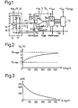
- FIG. 1 shows in a detailed representation a typical circuit for processing the analog air mass signal U H of the hot wire air mass meter for a downstream analog digital converter and FIGS. 2 and 3 the calibration curve of the hot wire air mass meter and the output values of the analog digital converter with the corresponding assigned Air volume values.
- the basic idea of the present invention is to enable an adjustment "over everything" in the fully assembled control unit by using the A / D converter + computer downstream of the input differential amplifier, on which the latter works, as measuring means.
- corresponding air mass signals U H are read in at the input of the differential amplifier, output again via a serial computer interface and preferably immediately compared with the expected digital values for realizing a fully automatic comparison and the comparison, also preferably by laser, to the Hybrid circuit, made.
- the input circuit which processes the analog hot wire air mass meter signal U H (hereinafter abbreviated as HLM signal) for scanning by the computer of the control unit comprises, according to FIG. 1, a differential amplifier 11 connected downstream of the hot wire air mass meter 10;
- the differential amplifier 11 is followed by an A / D converter 12, which converts the analog output voltages U AD supplied to it by the differential amplifier 11 into digital values and, via corresponding data and control line connections 13, feeds it to a downstream computer 14 which, in what This connection does not need to be discussed further, in the usual way receives further operating parameters of an internal combustion engine, for example information about speed, temperature, air temperature, idling, full load and the like.
- receives further operating parameters of an internal combustion engine for example information about speed, temperature, air temperature, idling, full load and the like.
- the duration of fuel injection pulses that are to be supplied to the internal combustion engine Like. And ultimately determined the duration of fuel injection pulses that are to be supplied to the internal combustion engine.
- the actual hot wire air mass meter designated in FIG. 1 consists of the hot wire 15 arranged in the intake pipe of an internal combustion engine in a bridge circuit (Wheatstone bridge) with three further resistors 16, 17 and 18 - the latter can also be a bridging terminal.
- a bridge circuit Woodstone bridge
- an operational amplifier 19 is also provided, the two inputs of which are connected to the bridge diagonal and the output of which feeds the bridge containing the actual hot wire, the output voltage being simultaneous due to the bridging terminal 18 is also present at the other input of the operational amplifier 19.
- the supply voltage for the operational amplifier 19 is designated + U B ; at the output of the hot-wire air mass meter, the HLM voltage U H drops and is replaced by a first R1 stood here on the inverting input of the downstream differential amplifier 11, - which is fed back via a resistor R2 or R2 * (changeable by adjustment) from the output.
- R3 resistors
- R4 adjustable
- the supply voltage for the differential amplifier 11 is again the voltage + U B ; what is useful for the following calculations, two further voltages are defined, namely the voltage drop across resistor R4 with U + and the voltage from the inverting connection to ground with U-; Between the two input connections of the differential amplifier 11, the offset voltage Uoff then results, as is known.
- the control unit ground SG ground is connected to the measuring ground via the hot wire air mass meter 10.
- a resistor R5 of, for example, 1 ohm is preferably connected between the two masses in the control device.
- the A / D converter Since the air wet signal U H represents an absolute value, the A / D converter must also be supplied with a reference voltage Uref.
- the maximum possible voltage offsets (U DIFF ⁇ 100 mV, jUref - U STAB
- the currents of any interference suppression capacitors must be kept away from the measuring mass, which is also important for lambda control.
- the design can therefore be carried out as follows, the stroke U H - U H min of the air volume signal U H to be processed determining the ratio of the resistors R1 and R2:
- Including the calibration curve profile of a special hot-wire air mass meter, as shown in numerical values in FIG. 2, and the output value profile of the analog-digi tal converter when using formulas 6 and 7 provide the calculation bases required for carrying out the adjustment to offset and amplification, the adjustment because the entire chain of input amplifier, analog digital converter, reference voltage and the like. Like. are afflicted with an error, is basically carried out in such a way that at least two analog voltage values, for example for relatively low and for relatively high air mass signals, are applied to the input of the differential amplifier 12 from a high-precision voltage source, and to a serial interface of the control unit 14 expected, corresponding digital values are recorded.
- An elegant adjustment method for the input amplifier 11 therefore consists in using the A / D -Converters 12 with a downstream computer as measuring means, a test program being activated in the computer, which reads in the U H values and outputs them again via a serial interface or, in the case of automatic execution, uses the deviation of the output digital values from the expected values to control the adjustment means Adjustment means are then again preferred laser devices which change the corresponding resistance values on the hybrid circuit, as explained in more detail below.
- the following table shows possible ranges of variation of the air mass flow in an intake pipe of an internal combustion engine in numerical values and on the basis of the calculation that has just been carried out.
- the gain can 1.9 can be selected, ie the last column of the table applies.
- the A / D converter 12 (ADC ⁇ 8 ⁇ 9) is specified from 0 ° to + 70 ° C for a maximum error of + - 1 LSB.
- the offset voltage of the differential amplifier 11 itself has no significant influence on the accuracy, since it is compensated for by adjustment.
- the voltage U ref may have a temperature drift of 60ppm / ° C.
Landscapes
- Physics & Mathematics (AREA)
- Fluid Mechanics (AREA)
- General Physics & Mathematics (AREA)
- Measuring Volume Flow (AREA)
- Combined Controls Of Internal Combustion Engines (AREA)
- Details Of Flowmeters (AREA)
Applications Claiming Priority (2)
| Application Number | Priority Date | Filing Date | Title |
|---|---|---|---|
| DE3520392 | 1985-06-07 | ||
| DE19853520392 DE3520392A1 (de) | 1985-06-07 | 1985-06-07 | Abgleichverfahren fuer einen hitzdraht-luftmassenmesser und hitzdraht-luftmassenmesser zur durchfuehrung des verfahrens |
Publications (2)
| Publication Number | Publication Date |
|---|---|
| EP0204183A1 true EP0204183A1 (fr) | 1986-12-10 |
| EP0204183B1 EP0204183B1 (fr) | 1989-05-10 |
Family
ID=6272649
Family Applications (1)
| Application Number | Title | Priority Date | Filing Date |
|---|---|---|---|
| EP86106495A Expired EP0204183B1 (fr) | 1985-06-07 | 1986-05-13 | Procédé d'étalonnage pour un débimètre massique d'air à fil chaud et débimètre massique d'air à fil chaud |
Country Status (3)
| Country | Link |
|---|---|
| EP (1) | EP0204183B1 (fr) |
| JP (1) | JPS61284610A (fr) |
| DE (2) | DE3520392A1 (fr) |
Cited By (4)
| Publication number | Priority date | Publication date | Assignee | Title |
|---|---|---|---|---|
| GB2276725A (en) * | 1993-04-01 | 1994-10-05 | Ford Motor Co | Calibrating a mass air flow sensor |
| EP1014046A4 (fr) * | 1996-09-13 | 2002-05-29 | Hitachi Ltd | Debimetre d'air thermique |
| EP1840536A1 (fr) * | 2006-03-31 | 2007-10-03 | Sensirion AG | Débitmètre avec convertisseur analogique-numérique adaptable en fonction du débit |
| CN117516671A (zh) * | 2024-01-05 | 2024-02-06 | 中国航空油料有限责任公司成都分公司 | 一种飞机加油车流量计检定的移动标准装置 |
Families Citing this family (8)
| Publication number | Priority date | Publication date | Assignee | Title |
|---|---|---|---|---|
| KR910002791B1 (ko) * | 1987-01-23 | 1991-05-04 | 미쓰비시 뎅끼 가부시기가이샤 | 에어프로센서용 입력처리회로 |
| DE3742443A1 (de) * | 1987-12-15 | 1989-07-06 | Bosch Gmbh Robert | Schaltungsanordnung zur digitalisierung eines analogsignals |
| JP2765881B2 (ja) * | 1988-11-09 | 1998-06-18 | 三菱電機株式会社 | 内燃機関の吸入空気量計測装置 |
| DE4130512A1 (de) * | 1991-09-13 | 1993-03-18 | Pierburg Gmbh | Signalabgleicheinrichtung |
| US5504681A (en) * | 1994-06-29 | 1996-04-02 | Ford Motor Company | Mass air flow sensor calibration |
| JP2929950B2 (ja) * | 1994-10-21 | 1999-08-03 | 株式会社日立製作所 | 内燃機関の制御装置 |
| KR100406898B1 (ko) * | 1995-10-20 | 2004-05-20 | 가부시키 가이샤 히다치 카 엔지니어링 | 차량용내연기관의제어방법및장치 |
| CN114624466B (zh) * | 2022-05-17 | 2022-07-12 | 西南石油大学 | 一种基于热线风速仪的试验装置及试验方法 |
Citations (2)
| Publication number | Priority date | Publication date | Assignee | Title |
|---|---|---|---|---|
| US4264961A (en) * | 1978-06-02 | 1981-04-28 | Hitachi, Ltd. | Air flow rate measuring apparatus |
| GB2107883A (en) * | 1981-10-08 | 1983-05-05 | Jaeger | Digital hot-wire liquid level detecting apparatus |
-
1985
- 1985-06-07 DE DE19853520392 patent/DE3520392A1/de not_active Withdrawn
-
1986
- 1986-05-13 DE DE8686106495T patent/DE3663306D1/de not_active Expired
- 1986-05-13 EP EP86106495A patent/EP0204183B1/fr not_active Expired
- 1986-05-20 JP JP61113815A patent/JPS61284610A/ja active Pending
Patent Citations (2)
| Publication number | Priority date | Publication date | Assignee | Title |
|---|---|---|---|---|
| US4264961A (en) * | 1978-06-02 | 1981-04-28 | Hitachi, Ltd. | Air flow rate measuring apparatus |
| GB2107883A (en) * | 1981-10-08 | 1983-05-05 | Jaeger | Digital hot-wire liquid level detecting apparatus |
Cited By (10)
| Publication number | Priority date | Publication date | Assignee | Title |
|---|---|---|---|---|
| GB2276725A (en) * | 1993-04-01 | 1994-10-05 | Ford Motor Co | Calibrating a mass air flow sensor |
| US5493892A (en) * | 1993-04-01 | 1996-02-27 | Ford Motor Company | Method for calibrating the time response of a mass air flow sensor by laser trimming selected resistors and without an air flow |
| GB2276725B (en) * | 1993-04-01 | 1996-10-02 | Ford Motor Co | Calibrating a mass air flow sensor |
| EP1014046A4 (fr) * | 1996-09-13 | 2002-05-29 | Hitachi Ltd | Debimetre d'air thermique |
| EP1840536A1 (fr) * | 2006-03-31 | 2007-10-03 | Sensirion AG | Débitmètre avec convertisseur analogique-numérique adaptable en fonction du débit |
| JP2007282218A (ja) * | 2006-03-31 | 2007-10-25 | Sensirion Ag | フロー適応可能アナログ−デジタルコンバータを備えるフローセンサ |
| US7490511B2 (en) | 2006-03-31 | 2009-02-17 | Sensirion Ag | Flow sensor with flow-adaptable analog-digital-converter |
| CN101046401B (zh) * | 2006-03-31 | 2011-08-24 | 森斯瑞控股股份公司 | 具有流量可适应的模数转换器的流量传感器 |
| CN117516671A (zh) * | 2024-01-05 | 2024-02-06 | 中国航空油料有限责任公司成都分公司 | 一种飞机加油车流量计检定的移动标准装置 |
| CN117516671B (zh) * | 2024-01-05 | 2024-04-09 | 中国航空油料有限责任公司成都分公司 | 一种飞机加油车流量计检定的移动标准装置 |
Also Published As
| Publication number | Publication date |
|---|---|
| EP0204183B1 (fr) | 1989-05-10 |
| JPS61284610A (ja) | 1986-12-15 |
| DE3520392A1 (de) | 1986-12-11 |
| DE3663306D1 (en) | 1989-06-15 |
Similar Documents
| Publication | Publication Date | Title |
|---|---|---|
| DE2917237C2 (fr) | ||
| EP0169414A2 (fr) | Méthode pour la compensation en température et montage de mesure pour cette méthode | |
| EP0221251B1 (fr) | Méthode pour compenser des erreurs d'un capteur à caractéristique non linéaire et dispositif pour sa mise en oeuvre | |
| EP0204183B1 (fr) | Procédé d'étalonnage pour un débimètre massique d'air à fil chaud et débimètre massique d'air à fil chaud | |
| DE3151743A1 (de) | Messgeraet mit vielelementenfuehler | |
| EP1001248A2 (fr) | Méthode de calibrage offset d'un palpeur d'angle magnéto-résistif | |
| EP0173833A2 (fr) | Montage et procédé pour la mesure et la digitalisation d'une résistance | |
| DE3309404C2 (fr) | ||
| DE69504537T2 (de) | Temperaturmessverfahren mit einem ntc-fühler und entsprechende anordnung | |
| EP0101956B1 (fr) | Thermomètre à résistance | |
| WO1987006339A1 (fr) | Circuit de detection de deformations mecaniques, en particulier sous pression | |
| DE69511183T2 (de) | Differenzverstärker mit Gleichtaktsignalkorrektur | |
| DE3831659A1 (de) | Einschaltung zum eichen eines ohmmeters | |
| DE2518890A1 (de) | Linearisierungsvorrichtung | |
| DE19837440C2 (de) | Analog/Digital-Wandlervorrichtung und Regelvorrichtung für einen Gradientenverstärker | |
| EP1156299B1 (fr) | Transducteur de mesure pour capteurs de position potentiométriques et procédé de réglage des paramètres | |
| DE1951220A1 (de) | Verfahren und Einrichtung zur Analyse von Proben | |
| DE1914596A1 (de) | Vorrichtung zur Messung durch Ermittlung der Temperatur eines durch Joule-Effekt geheizten Heizfadens | |
| DE2710782C2 (de) | Vorrichtung zur Messung von Temperaturdifferenzen | |
| DE69006162T2 (de) | Anordnung für elektronische schaltung. | |
| DE3313043C2 (fr) | ||
| DE2203927A1 (fr) | ||
| DE2460079B2 (de) | Verfahren zur Bestimmung der Stellung des Schleifen eines Potentiometers und Schaltungsanordnung zur Durchführung des Verfahrens | |
| EP1132794B1 (fr) | Methode d'obtention d'une référence de tension en dépendance de temperature et une circuit d'en obtenir | |
| DE4013089A1 (de) | Verfahren zur fehlerkorrigierten messung einer elektrischen groesse |
Legal Events
| Date | Code | Title | Description |
|---|---|---|---|
| PUAI | Public reference made under article 153(3) epc to a published international application that has entered the european phase |
Free format text: ORIGINAL CODE: 0009012 |
|
| AK | Designated contracting states |
Kind code of ref document: A1 Designated state(s): DE FR GB IT SE |
|
| 17P | Request for examination filed |
Effective date: 19870226 |
|
| 17Q | First examination report despatched |
Effective date: 19880915 |
|
| GRAA | (expected) grant |
Free format text: ORIGINAL CODE: 0009210 |
|
| AK | Designated contracting states |
Kind code of ref document: B1 Designated state(s): DE FR GB IT SE |
|
| PGFP | Annual fee paid to national office [announced via postgrant information from national office to epo] |
Ref country code: FR Payment date: 19890614 Year of fee payment: 4 |
|
| REF | Corresponds to: |
Ref document number: 3663306 Country of ref document: DE Date of ref document: 19890615 |
|
| ET | Fr: translation filed | ||
| GBT | Gb: translation of ep patent filed (gb section 77(6)(a)/1977) | ||
| PGFP | Annual fee paid to national office [announced via postgrant information from national office to epo] |
Ref country code: SE Payment date: 19890717 Year of fee payment: 4 |
|
| PGFP | Annual fee paid to national office [announced via postgrant information from national office to epo] |
Ref country code: DE Payment date: 19890727 Year of fee payment: 4 |
|
| ITF | It: translation for a ep patent filed | ||
| PLBE | No opposition filed within time limit |
Free format text: ORIGINAL CODE: 0009261 |
|
| STAA | Information on the status of an ep patent application or granted ep patent |
Free format text: STATUS: NO OPPOSITION FILED WITHIN TIME LIMIT |
|
| 26N | No opposition filed | ||
| PG25 | Lapsed in a contracting state [announced via postgrant information from national office to epo] |
Ref country code: GB Effective date: 19900513 |
|
| PG25 | Lapsed in a contracting state [announced via postgrant information from national office to epo] |
Ref country code: SE Effective date: 19900514 |
|
| ITTA | It: last paid annual fee | ||
| GBPC | Gb: european patent ceased through non-payment of renewal fee | ||
| PG25 | Lapsed in a contracting state [announced via postgrant information from national office to epo] |
Ref country code: FR Effective date: 19910131 |
|
| PG25 | Lapsed in a contracting state [announced via postgrant information from national office to epo] |
Ref country code: DE Effective date: 19910201 |
|
| REG | Reference to a national code |
Ref country code: FR Ref legal event code: ST |
|
| EUG | Se: european patent has lapsed |
Ref document number: 86106495.4 Effective date: 19910115 |
|
| PG25 | Lapsed in a contracting state [announced via postgrant information from national office to epo] |
Ref country code: IT Free format text: LAPSE BECAUSE OF NON-PAYMENT OF DUE FEES;WARNING: LAPSES OF ITALIAN PATENTS WITH EFFECTIVE DATE BEFORE 2007 MAY HAVE OCCURRED AT ANY TIME BEFORE 2007. THE CORRECT EFFECTIVE DATE MAY BE DIFFERENT FROM THE ONE RECORDED. Effective date: 20050513 |