EP0204227B1 - Papierzuführungsvorrichtung - Google Patents
Papierzuführungsvorrichtung Download PDFInfo
- Publication number
- EP0204227B1 EP0204227B1 EP86107006A EP86107006A EP0204227B1 EP 0204227 B1 EP0204227 B1 EP 0204227B1 EP 86107006 A EP86107006 A EP 86107006A EP 86107006 A EP86107006 A EP 86107006A EP 0204227 B1 EP0204227 B1 EP 0204227B1
- Authority
- EP
- European Patent Office
- Prior art keywords
- paper
- lever
- roller
- lift
- feeding device
- Prior art date
- Legal status (The legal status is an assumption and is not a legal conclusion. Google has not performed a legal analysis and makes no representation as to the accuracy of the status listed.)
- Expired
Links
- 238000005520 cutting process Methods 0.000 claims description 2
- 238000003780 insertion Methods 0.000 claims 2
- 230000037431 insertion Effects 0.000 claims 2
- 230000037361 pathway Effects 0.000 claims 2
- 238000011144 upstream manufacturing Methods 0.000 claims 2
- 239000000203 mixture Substances 0.000 description 8
- 230000005540 biological transmission Effects 0.000 description 7
- 238000003825 pressing Methods 0.000 description 6
- 238000004519 manufacturing process Methods 0.000 description 4
- 230000003287 optical effect Effects 0.000 description 4
- 238000003860 storage Methods 0.000 description 4
- 108091008695 photoreceptors Proteins 0.000 description 3
- 238000005452 bending Methods 0.000 description 2
- 238000012840 feeding operation Methods 0.000 description 2
- 230000033001 locomotion Effects 0.000 description 2
- 229910000831 Steel Inorganic materials 0.000 description 1
- 210000000078 claw Anatomy 0.000 description 1
- 230000001419 dependent effect Effects 0.000 description 1
- 239000011521 glass Substances 0.000 description 1
- 238000010438 heat treatment Methods 0.000 description 1
- 238000009434 installation Methods 0.000 description 1
- 239000010959 steel Substances 0.000 description 1
- 229920003002 synthetic resin Polymers 0.000 description 1
- 239000000057 synthetic resin Substances 0.000 description 1
Images



Classifications
-
- B—PERFORMING OPERATIONS; TRANSPORTING
- B65—CONVEYING; PACKING; STORING; HANDLING THIN OR FILAMENTARY MATERIAL
- B65H—HANDLING THIN OR FILAMENTARY MATERIAL, e.g. SHEETS, WEBS, CABLES
- B65H1/00—Supports or magazines for piles from which articles are to be separated
- B65H1/26—Supports or magazines for piles from which articles are to be separated with auxiliary supports to facilitate introduction or renewal of the pile
- B65H1/266—Support fully or partially removable from the handling machine, e.g. cassette, drawer
-
- B—PERFORMING OPERATIONS; TRANSPORTING
- B65—CONVEYING; PACKING; STORING; HANDLING THIN OR FILAMENTARY MATERIAL
- B65H—HANDLING THIN OR FILAMENTARY MATERIAL, e.g. SHEETS, WEBS, CABLES
- B65H1/00—Supports or magazines for piles from which articles are to be separated
- B65H1/04—Supports or magazines for piles from which articles are to be separated adapted to support articles substantially horizontally, e.g. for separation from top of pile
-
- B—PERFORMING OPERATIONS; TRANSPORTING
- B65—CONVEYING; PACKING; STORING; HANDLING THIN OR FILAMENTARY MATERIAL
- B65H—HANDLING THIN OR FILAMENTARY MATERIAL, e.g. SHEETS, WEBS, CABLES
- B65H3/00—Separating articles from piles
- B65H3/02—Separating articles from piles using friction forces between articles and separator
- B65H3/06—Rollers or like rotary separators
- B65H3/0669—Driving devices therefor
-
- B—PERFORMING OPERATIONS; TRANSPORTING
- B65—CONVEYING; PACKING; STORING; HANDLING THIN OR FILAMENTARY MATERIAL
- B65H—HANDLING THIN OR FILAMENTARY MATERIAL, e.g. SHEETS, WEBS, CABLES
- B65H3/00—Separating articles from piles
- B65H3/02—Separating articles from piles using friction forces between articles and separator
- B65H3/06—Rollers or like rotary separators
- B65H3/0676—Rollers or like rotary separators with two or more separator rollers in the feeding direction
-
- B—PERFORMING OPERATIONS; TRANSPORTING
- B65—CONVEYING; PACKING; STORING; HANDLING THIN OR FILAMENTARY MATERIAL
- B65H—HANDLING THIN OR FILAMENTARY MATERIAL, e.g. SHEETS, WEBS, CABLES
- B65H3/00—Separating articles from piles
- B65H3/46—Supplementary devices or measures to assist separation or prevent double feed
- B65H3/52—Friction retainers acting on under or rear side of article being separated
- B65H3/5207—Non-driven retainers, e.g. movable retainers being moved by the motion of the article
- B65H3/5215—Non-driven retainers, e.g. movable retainers being moved by the motion of the article the retainers positioned under articles separated from the top of the pile
- B65H3/5223—Retainers of the pad-type, e.g. friction pads
-
- G—PHYSICS
- G03—PHOTOGRAPHY; CINEMATOGRAPHY; ANALOGOUS TECHNIQUES USING WAVES OTHER THAN OPTICAL WAVES; ELECTROGRAPHY; HOLOGRAPHY
- G03G—ELECTROGRAPHY; ELECTROPHOTOGRAPHY; MAGNETOGRAPHY
- G03G15/00—Apparatus for electrographic processes using a charge pattern
- G03G15/65—Apparatus which relate to the handling of copy material
- G03G15/6502—Supplying of sheet copy material; Cassettes therefor
Definitions
- the present invention relates to a paper feeding device of the kind referred to in the preamble of patent claim 1.
- a feeding device is known from JP-A-203629/1982.
- Image processing apparatus such as copying machines and facsimile units are hitherto provided with a paper feeding device having a paper cassette and/or a stack bypass enabling to set a number of sheets of image forming paper, and/or a paper feeding device having an automatic document feeder enabling to set a number of sheets of documents.
- the paper feeding device having the aforementioned paper feed cassette is advantageous in that the cassette can be changed easily when it is necessary to use a paper of different size.
- the document size to be copied recently tends to become larger, and a larger size of paper cassette has been used to accept a larger image forming paper corresponding to larger documents which are to be copied.
- a reverse paper feeding device in which a direction of paper feeding from the paper cassette by the feed roller is set in opposite to a direction of paper feeding by a resist roller which operates synchronously with the optical system.
- the whole copying machine can be made compact even with the paper cassette being mounted by thereon so that the paper cassette may not be projected from the area of a vertical projection, for example, of the optical system which requires the largest plane size.
- Such a reversing paper feeding device is composed of a feed roller to send out each sheet of paper from the paper cassette, a delivery roller to carry the paper fed from the feed roller toward a resist roller, and a guide member to reverse a direction of the paper carried by the delivery roller.
- the driving of feed roller and the resist roller are controlled in timing with a specific paper feeding, and driving of the delivery roller is also controlled in timing with the specific paper feeding by using a clutch or the like.
- the feed roller and the delivery roller are driven to rotate enabling the preliminary paper feeding to the point where the front end of paper comes in contact with the resist roller, thereafter the delivery roller and the resist roller are driven to rotate enabling a paper feeding for accomplishing a copying operation.
- the installation area of the copying machine can be made smaller and exact paper feeding can be ensured. It is necessary, however, to control the driving of the delivery roller corresponding to the driving condition of the feed roller and the resist roller, which makes the electrical control system and mechanical revolution transfer mechanism disadvantageously more intricated. Further the device is also disadvantageous in that the position of the delivery roller attached is rather limited making it difficult to design the whole paper feeding device, and additional members are necessary to attach the delivery roller.
- a pressing mechanism to upwardly turn a document setting board mounted in the paper feed cassette so as to be turned freely is provided in the copying machine, and a pressure releasing lever mechanism to stop upward-turning of the document setting board by a means of pressure mechanism is also attached.
- the document setting board can be upwardly turned simply by mounting a paper feed cassette, but the paper feeding device is disadvantageous in that the operation of pulling out the paper cassette is troublesome because the pressure release lever mechanism must be operated before pulling out the cassette.
- the need of a pressure release lever mechanism in addition to the pressure mechanism makes the composition -of the whole paper feeding device more intricated and the manufacturing cost higher.
- the front end of the next paper is positioned between the feed roller and the friction pad by the friction force between adjacent sheets of papers when feeding of one sheet, of paper completes. If copying operation is continued as it is, there will be no problem, however, if it is necessary to change the paper size or the like, a new paper cassette must be mounted after pulling out the currently used paper cassette. While the cassette is changed, the paper of which top end is held between the feed roller and the friction pad remains in the copying machine, and a new paper feed cassette is set under this condition. Accordingly, the remaining paper is greatly crumpled or folded, and a jamming is finally resulted if the copying operation is kept going on.
- a paper feeding device as for example known from JP-A-203629/1982 has been proposed, in which the contact condition of the feed roller with the friction pad is released when the paper cassette is pulled out to prevent the paper from remaining in the copying machine.
- the problem is outstanding particularly for the type of copying machine in which almost part of the paper cassette is housed into the copying machine because the remaining paper can't be watched or checked easily from outside.
- the aforementioned paper feeding device containing a stack bypass or an automatic document feeder has a preliminary feed roller and a feed roller and the preliminary feed roller is moved in opposite direction to paper pressing direction by a solenoid, a lever, a cam and the like under the condition where transmission of the driving force of the both rollers is cut off so that a number of sheets of paper can be set easily and exactly at the specified position.
- the preliminary feed roller is moved in paper pressing direction by the solenoid, the lever, the cam and the like and the both rollers are driven under this condition so that the paper is carried sheet by sheet.
- the papers could be set rather easily at the specified position provided that the number of sheets of paper is comparatively small because the tangential direction of the preliminary feed roller at the point where the upper sheet of paper comes in contact is close to the horizontal direction and the preliminary feed roller can be upwardly moved against the applied force.
- the tangential direction of the preliminary feed roller at the point where the upper top of paper comes in contact rises sharply and the vertical component of the force to upwardly move the preliminary feed roller against the applied force is quickly reduced, making it difficult to set the papers at the specified position.
- the paper feeding device of the aforementioned composition requires a mechanism to move the preliminary feed roller and also a means to control the mechanism, which is disadvantageous in that the whole paper feeding mechanism is intricated and the manufacturing cost is raised.
- JP-A-203629/1982 discloses a paper feeding device provided on an image processing apparatus, for withdrawing by a feed roller, sheet by sheet, a sheet of paper disposed in a stack of papers within a paper cassette set substantially within a housing of the image processing apparatus reversing the in- ital direction of conveyance of the sheet of paper being fed, and delivering the sheet of paper to a resist roller being driven so as to rotate synchronously with the operation of an image processing section of the image processing apparatus.
- a further object of the invention is to make the whole paper feeding device simple by eliminating the complicated mechanism to move the preliminary feed roller and the means to control that mechanism so as to make the manufacturing cost lower.
- Fig. 1 shows the outline of the internal mechanism of a copying machine incorporated with a paper feeding device according to the present invention.
- the whole housing (1) of the copying machine, the part incorporating the optical system (2) comprising a lamp, reflecting mirrors, and a lens is made wider and the other part incorporating the copying section (3) and the paper conveying section (4) is made narrower.
- a contact glass (11) to set documents to be copied is provided at the specified position on the housing (1) of the copying machine.
- the optical system (2) comprises a lamp (21) to scan and expose documents while moving at a specified speed, reflecting mirrors (22) (23) (24) to lead the reflected light from the documents to a lens (25) while moving the lamp (21), and a reflecting mirror (26) to lead the light coming through the lens (25) to the copying section (3).
- the copying section (3) comprises a photoreceptor drum (31) which turns in one direction at every copying operation, corona dischargers (32), a developing device (33), a transferring corona discharger (34), a separating belt (35) and a cleaner (36) provided around the photoreceptor drum (31).
- the paper conveying section (4) has the first paper feeding device (5) to feed out paper (P) sheet by sheet from the paper feed cassette (12) set on lower position of the copying section (3), a resist roller (41) driven synchronously with transferring of the lamp (21), a delivery roller (42) to carry the paper (P) separated from the photoreceptor drum (31) by the separating belt (35), a heating and fusing device (43), and a discharge roller (44) to discharge the paper (P) onto a discharge tray (15).
- a preliminary feed roller (103) to carry the paper (P) to the resist roller (41) and the 2nd paper feeding device (10) primarily made of a feed roller (102) are also attached to a specific position of a document tray (101) at a specific position of the copying machine housing (1) to enable selection of paper feed from the paper feed cassette (12) and from the document tray (101).
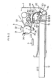
- Fig. 2 to Fig. 5 show the detailed composition of the 1 st paper feeding device (5), which is primarily composed of a feed roller (51), delivery roller (52), driven roller (53) as a driven member, and a guide (55).
- the feed roller (51) rotates while being pressed against the surface of the paper (P) held by a document setting board (13) which is turned upward by the lift-up lever (14) attached to a specific position in the copying machine housing (1) so as to feed out of paper (P) sheet by sheet and the paper is lead between the feed roller (51) and the friction pad (58) so that double paper feeding is prevented exactly.
- an auxiliary roller (51c) to press the paper (P) on the end thereof is attached, in a manner to slide freely, to a sheet (51 a) to which the feed roller (51) is also attached.
- sliding range of the auxiliary roller (51 c) is limited by a rib (57a) projected from outer surface of the inner guide member (57) as described later. Accordingly, manufacturing and assembling become easy.
- the auxiliary roller (51 c) may be fixed to the shaft (51 a) in advance, but attaching accuracy of the auxiliary roller (51 c) must be higher in this case.
- the friction pad (58) is fixed to a contact member (12a) which regulates setting position of the paper cassette (12) and is formed narrower than the feed roller (51).
- the paper (P) is allowed to be bent further along the feed roller (51) and the friction pad (58) to provide a space (59) where front end of the paper (P) can be corrected.
- the delivery roller (52) is normaly turned and the driven roller (53) is pressed against the delivery roller (52) by a plate spring (54) are attached, and the guide member (55) composed of an outer guide plate (56) and an inner guide member (57) is attached between the normally rotated delivery roller (52) or the driven roller (53) and aforementioned resist roller (41).
- the paper cassette (12) has a document setting board (13) which can be turned in up-and-down direction when mounted onto the copying machine housing (1) and by taking a specific position at outer side as the fulcrum point, and also a rectangular opening (63) formed along the front end of the bottom plate of the paper feed cassette (12) to the bottom of the front plate.
- a support (65) is fixed to the inner end of the bottom plate (64) of the copying machine housing (1) and a lift-up lever (14) is turnably attached between a set of brackets (66a) and (66b) provided on the support (65).
- One bracket (66a) is fixed onto the support (65) with a set screw (67) and the other bracket (66b) is made in one piece with the support (65) by bending a part of the support (65), and the push lever (14) is held so as to turn upward and downward by projections (14a) (14b) provided at both sides of the bent part in the middle of the lift-up lever (14) and inserted into through holes (66c) (66d) made on the brackets (66a) (66b).
- a stopper dent (14c) is also provided on the base of the lift-up lever (14) and another stopper dent (68a) is also provided on a bent part (68) at an inner side of the support (65), and a coil spring (69) to turn the lift-up lever (14) upward (clockwise direction in Fig. 4 and Fig. 5) is provided between the stopper dents (14c) and (68a).
- a locking means (70) is provided in addition, which is composed of a locking mechanism (71) to lock the lift-up lever (14) in downward turning condition and of an lock-releasing mechanism (72) to release locking into upward turning condition.
- the lock-releasing mechanism (72) has a release lever (75) of an arc shape and supports the release lever (75) between a pair of brackets (76a) (76b) provided on the support (65) in a manner that the lever can be turned freely.
- one bracket (76a) is made in one piece with the support (65) by bending a part of the support, and the other bracket (76b) is fixed onto the support by a set screw (77) and the release lever (75) is supported so as to turn freely by the projections (75a) (76b) at both sides of the base of the unlocking lever (75) inserted into the through holes (76c) (76d) provided on the brackets (76a) (76b).
- a plate spring (78) bent to approximately U-shape is fixed onto the support (65) with a screw (79) and the top end is put in contact with the outer face of the release lever (75) to turn the release lever (75) to the direction of the paper cassette (12) (counter-clockwise direction in Fig. 4 and Fig. 5).
- the interlocked projection (75c) is provided on the release lever (75) corresponding to the interlocking projection (14d) provided on the lift-up lever (14).
- the interlocking projection (14d) interlocks with the interlocked projection (75c)
- upward turning of the liftup lever (14) by the coil spring (69) is prevented as shown in Fig. 4. i.e. locking condition is selected.
- the unlocking lever (75) has a top end which comes in contact with the front plate of the paper cassette (12) mounted onto the copying machine, and operating pieces (80) extending downward diagonally are provided at the front side of the front plate of the paper feed cassette (12). There are two operating pieces (80) provided with certain spacing in a transversal direction of the paper feed cassette (12). Corresponding to the operating pieces (80), contained pieces (81) are provided at the top side of the lift-up lever (14).
- the contacted pieces (81) are made of a contacted member (82) of triangular shape provided at a side of the lift-up lever (14), and a contacted roller (84) supported at the side with a short shaft (83) so as to turn freely, and the surface of the contacted member (82) is inclined upward to the side of the contracted roller (84).
- the contact member (12a) has a contact part (12b) extending substantially vertically upward and an inclined part (12c) extending upward slantwise from the top end of the contact part (12b) in paper carrying direction, and covers the top of the support (65).
- the top side of the lift-up lever (14) and the top end of the release lever (75) are projected through an opening (12d) formed at approximately the center in transversal direction of the contact member (12b) (width-direction of the paper P).
- a housing space (64a) is provided to accept the top end of the lift up lever (14) when the lever (14) turns downward.
- a rack (86) is made at the upper front of one side plate of the paper cassette, and a storage space (87) is provided immediately after the back side of the rack (86).
- Driving force of the driving power source is transmitted at a specified timing to one end of the shaft (51 a) to which the feed roller (51) is attached through a driving force transmission mechanism comprising a gear (88a) and a clutch (88b).
- a gear (89), a gear attaching plate (90) and a lever (91) are attached to the other end of the shaft (51 a).
- a gear (92) to be interlocked with the gear (89) and another gear (93) to be interlocked with the gear (92) are attached.
- the lever (91) and the gear attaching plate (90) are turned downward around the shaft (51 a) by a tension spring (94) provided between the top end of the lever (91) and a fixed point in the copying machine housing (1).
- the storage space (57) is provided at a position where the gear (93) can be housed when the paper feed cassette (12) is mounted completely so that the gear (93) following revolution of the feed roller (51) for paper feeding can be turned freely.
- the feed roller (51) can also be turned in reverse direction to paper feeding by the gear (93) interlocked with the rack (86) following pull-out motion of the paper cassette (12).
- the inner guide member (57) is totally made of synthetic resin and a plurality of ribs with convex curvature on the side are provided on the outer surface of the guide member.
- An outer guide plate (56) made of steel or the like is attached with about 1 mm spacing to the top of the ribs and the space between the ribs and the outer guide plate is used for paper transfer.
- the feed roller (52) is supported, in a manner to turn freely, at a position a little off the above mentioned space of the inner guide member (57), and a switch (60) to detect the paper (P) is held immediately before the resist roller (41).
- the driven roller (53) is attached to an opening and closing member (61) which is held onto the copying machine housing (1) by a plate spring (54) so as to be opened and closed.
- the driven roller (53) When the opening and closing member (61) is opened, the driven roller (53) is kept off the feed roller (52), and under closed condition of the opening and closing member (61), the driven roller (53) is pressed in contact with the feed roller (52).
- the pressure of the plate spring (54), however, is set smaller than the firmness of the paper (P).
- the magnet (62) is to keep the opening and closing (61) at closed condition.
- the front side plate comes in contact with the top end of the release lever (75) just before the end of setting of the paper feed cassette (12) i.e. immediately before the front plate of the paper cassette (12) comes in contact with the contact part (12b) of the contact member (12a), then the release lever (75) turns clockwise against the pressure of the plate spring (78) as the paper feed cassette (12) moves.
- the interlocking projection (14d) of the push lever (14) is released from the interlocked projection (75c) of the release lever (75), then the lift-up lever (14) is turned upward by the coil spring (69) to turn the document setting board (13) upward (counter-clockwise direction in Fig. 5) and to put the feed roller (51) in pressed contact with the paper (P) at the top thereof (See Fig. 5.). Accordingly, rotary force is transmitted to the shaft (51a) through the driving force transmission mechanism comprising the gear (88a) and the clutch (88b) and the feed roller (51) is rotated in the direction indicated by an arrow (51 b) to feed the paper (P) out of the paper feed cassette (12).
- the friction resistance between the friction pad (58) and the paper (P) functions to feed ut the upper-most paper (P).
- the gear (93) is also rotated but the rotation is idle as it is housed in the storage spaces (87) and causes no problem.
- the sheet of paper (P) sent out between the feed roller (51) and the friction pad (58) is led through the space (59) to the position between the delivery roller (52) and the driven roller (53). Since revolution of the delivery roller (52) is applied as the carrying force of the paper (P), the carrying force is sufficient to carry the paper (P) to put in contact with the resist roller (41, going through the guide (55). Even after the front end of the paper (P) touches the resist roller (41), the paper (P) is carried further for certain time by the feed roller (51), and the paper (P) fits along the whole surface of the outer guide plate (56) as shown by the continuous line in Fig. 2.
- the driven roller (53) is moved against the pressure of the spring (54), which serves to keep the paper (P) under the condition of no carrying force applied although the delivery roller (52) is kept turning.
- the driven roller (53) is slightly moved but the contact pressure to the delivery roller (52) is lessened and the delivery roller slips on the the paper (P) thus the transport of the paper (P) is stopped.
- the feed roller (51) is kept suspended, and the friction between the friction pad (58) and the paper (P) functions as resisting force.
- the paper (P) is immediately pulled and fitted along the outer surface of the inner guide member (57), as shown by the broken line in Fig. 2, as firmness of the paper (P) is no longer enough to separate the driven roller (53) from the delivery roller (52).
- the driven roller (53) is strongly pressed, therefore, to the delivery roller (52) and revolution of the delivery roller (52) functions for carrying the paper (P) without any slipping.
- the carrying force applied to the paper (P) by the resist roller (41) and the delivery roller (52) overcomes the resistance to complete the paper feeding to the copying section (3).
- the release lever (75) first turns downward following transfer of the paper feed cassette (12) to the outside (left side in Fig. 2).
- the paper feed cassette (12) moves outward further to go off the top of the release lever (75), then each one of the operating piece (80) comes in contact with the contacted part (81) to turn the lift-up lever (14) downward.
- the interlocking projection (34d) interlocks with arc-shaped inner surface of the unlocking lever (75) to turn the unlocking lever (75) upward, then the interlocking projection (14d) goes over the interlocking projection (75c). Accordingly, downward turning the lift-up lever (14) can be maintained by the interlocking projection (14d) interlocked with the interlocked projection (75c) even if the paper cassette (12) move outward further and downward turning power of the lift-up lever (14) by the operating piece (80) is no longer effective.
- the gear (93) goes off the storage space (87) and is interlocked with the rack (86) (See Fig.10.). Accordingly, the gear (93) rotates following outward movement of the paper feed cassette (12) and rotary force in reverse direction to paper feeding is transmitted to the shaft (51a) through the gears (92) (89). In this case, transmission of the driving force is normally shut off by the clutch (88b), and the feed roller (51) is rotated in reverse direction to paper feeding, and the paper (P) of which the top end is caught between the feed roller (51) and the friction pad (58) is carried in reverse direction, i.e. to the paper feed cassette (12) so as to be free.
- upward or downward turning of the lift-up lever (14) is selected automatically following setting and pulling-out of the paper cassette (12) resulting in easy setting and pulling-out of the cassette (12).
- the feed roller (51) turns in reverse direction to paper feeding in the initial stage of pulling, and top end of the paper (P) is not caught between the feed roller (51) and the friction pad (58) and the contact area of the paper with the friction pad (58) is kept less. This serves to pull out the paper (P) completely together with the paper feed cassette (12) and prevents the paper (P) from the remaining in the copying machine housing (1
- the driven roller (53) is not necessarily required and can be omitted because carrying force transmission condition and slip condition can be selected only if the contact pressure to the delivery roller (52) can be changed according to transfer condition of the paper (P).
- the contacted member (82) can also be omitted and it is possible to provide the operating piece (80) and the contacted part (81) at one side only.
- rollers (89') (92') (93') for driving power transmission are used in place of the gears (89) (92) (93) as the mechanism to turn the feed roller (51) in reverse direction to paper feeding, as shown in Fig. 11, and a friction pad (86') is used instead of the rack (86), it is possible to turn the roller (93') following transfer of the paper cassette (12) by the friction force between the friction pad (86') and the roller (93') and to turn the feed roller (51) in reverse direction to paper feeding.
- the feed roller (51) can be rotated in reverse direction to paper feeding by turning the rachet gear (93") only at the pulling-out operation of the paper feed cassette (12).
Landscapes
- Engineering & Computer Science (AREA)
- Mechanical Engineering (AREA)
- Physics & Mathematics (AREA)
- General Physics & Mathematics (AREA)
- Sheets, Magazines, And Separation Thereof (AREA)
Claims (15)
Applications Claiming Priority (10)
| Application Number | Priority Date | Filing Date | Title |
|---|---|---|---|
| JP112399/85 | 1985-05-24 | ||
| JP60112399A JPH0659943B2 (ja) | 1985-05-24 | 1985-05-24 | 給紙装置 |
| JP117175/85 | 1985-05-30 | ||
| JP60117175A JPH0639297B2 (ja) | 1985-05-30 | 1985-05-30 | 反転給紙装置 |
| JP60197621A JPH0714769B2 (ja) | 1985-09-09 | 1985-09-09 | 複写紙カセツトを備えた給紙機構 |
| JP197621/85 | 1985-09-09 | ||
| JP13932285U JPH045477Y2 (de) | 1985-09-10 | 1985-09-10 | |
| JP139322/85U | 1985-09-10 | ||
| JP2995086U JPS62144240U (de) | 1986-02-28 | 1986-02-28 | |
| JP29950/86U | 1986-02-28 |
Related Child Applications (2)
| Application Number | Title | Priority Date | Filing Date |
|---|---|---|---|
| EP89114543.5 Division-Into | 1989-08-07 | ||
| EP89114544.3 Division-Into | 1989-08-07 |
Publications (3)
| Publication Number | Publication Date |
|---|---|
| EP0204227A2 EP0204227A2 (de) | 1986-12-10 |
| EP0204227A3 EP0204227A3 (en) | 1987-03-11 |
| EP0204227B1 true EP0204227B1 (de) | 1990-09-12 |
Family
ID=27521188
Family Applications (3)
| Application Number | Title | Priority Date | Filing Date |
|---|---|---|---|
| EP89114543A Expired - Lifetime EP0349012B1 (de) | 1985-05-24 | 1986-05-23 | Papierzufuhrvorrichtung |
| EP89114544A Expired - Lifetime EP0349013B1 (de) | 1985-05-24 | 1986-05-23 | Papierzufuhrvorrichtung |
| EP86107006A Expired EP0204227B1 (de) | 1985-05-24 | 1986-05-23 | Papierzuführungsvorrichtung |
Family Applications Before (2)
| Application Number | Title | Priority Date | Filing Date |
|---|---|---|---|
| EP89114543A Expired - Lifetime EP0349012B1 (de) | 1985-05-24 | 1986-05-23 | Papierzufuhrvorrichtung |
| EP89114544A Expired - Lifetime EP0349013B1 (de) | 1985-05-24 | 1986-05-23 | Papierzufuhrvorrichtung |
Country Status (3)
| Country | Link |
|---|---|
| US (3) | US4813612A (de) |
| EP (3) | EP0349012B1 (de) |
| DE (3) | DE3689591T2 (de) |
Families Citing this family (39)
| Publication number | Priority date | Publication date | Assignee | Title |
|---|---|---|---|---|
| JPH0764482B2 (ja) * | 1987-07-31 | 1995-07-12 | 三田工業株式会社 | 中間トレイのコピー用紙送り装置 |
| US5593150A (en) * | 1987-08-18 | 1997-01-14 | Canon Kabushiki Kaisha | Sheet feeding apparatus for a recording apparatus |
| JPH0734142B2 (ja) * | 1988-09-27 | 1995-04-12 | 三田工業株式会社 | 画像形成装置 |
| JPH07106807B2 (ja) * | 1988-11-17 | 1995-11-15 | 三田工業株式会社 | 自動原稿搬送装置 |
| JPH03192039A (ja) * | 1989-12-18 | 1991-08-21 | Matsushita Graphic Commun Syst Inc | 画像読取装置 |
| US5368285A (en) * | 1991-02-28 | 1994-11-29 | Canon Kabushiki Kaisha | Automatic sheet feeding apparatus |
| JPH04286550A (ja) * | 1991-03-11 | 1992-10-12 | Canon Inc | シート材給送装置 |
| JP2943415B2 (ja) * | 1991-03-19 | 1999-08-30 | キヤノン株式会社 | 給紙装置及びそれを用いた画像形成装置 |
| JP2660181B2 (ja) * | 1991-04-09 | 1997-10-08 | 富士写真フイルム株式会社 | シート材の自動供給装置 |
| JP2879527B2 (ja) * | 1994-02-15 | 1999-04-05 | キヤノン株式会社 | シート材給送装置および画像形成装置 |
| JP3448097B2 (ja) * | 1994-05-19 | 2003-09-16 | ブラザー工業株式会社 | 給紙装置 |
| TW341955U (en) * | 1994-09-30 | 1998-10-01 | Mita Industrial Co Ltd | Device for conveying sheet members |
| DE19581389T1 (de) * | 1994-10-06 | 1996-12-05 | Pfu Ltd | Verfahren und Vorrichtung zur Papierzuführung für einen Drucker |
| US6149045A (en) * | 1995-04-26 | 2000-11-21 | Toshiba Tec Kabushiki Kaisha | Paper sheet supplying apparatus having a raised central region for preventing a paper sheet from skewing as the sheet is fed |
| JP3521102B2 (ja) * | 1996-02-27 | 2004-04-19 | 株式会社リコー | 給紙装置 |
| GB2312667B (en) * | 1996-05-02 | 2000-09-06 | Lexmark Int Inc | Sheet separator |
| JP3675055B2 (ja) * | 1996-09-03 | 2005-07-27 | ブラザー工業株式会社 | 給紙装置及び印字装置 |
| US5996989A (en) * | 1997-05-02 | 1999-12-07 | Lexmark International, Inc. | Sheet separator friction pad |
| US5895040A (en) * | 1997-06-20 | 1999-04-20 | Lexmark International, Inc. | Sheet separator |
| US6315282B2 (en) * | 1997-06-27 | 2001-11-13 | Hewlett-Packard Company | Apparatus and a method for picking multiple-sized media sheets |
| IT1307034B1 (it) * | 1999-04-12 | 2001-10-23 | Olivetti Lexikon Spa | Dispositivo per l'alimentazione di fogli da una risma del tipocomprendente un rullo principale di avanzamento ed un rullo |
| TW477748B (en) * | 2000-02-18 | 2002-03-01 | Acer Peripherals Inc | Feeding paper system having taking paper and distributing paper mechanism |
| DE60123712T2 (de) * | 2000-08-08 | 2007-08-16 | Ricoh Co., Ltd. | Blattzuführverfahren und Vorrichtung für eine Bilderzeugungsvorrichtung |
| US6471203B2 (en) * | 2000-12-22 | 2002-10-29 | Umax Data Systems | Paper separating device of the automatic document feeder |
| TW483833B (en) * | 2001-05-03 | 2002-04-21 | Benq Corp | Paper feeding mechanism |
| US6896253B2 (en) * | 2001-05-10 | 2005-05-24 | Canon Kabushiki Kaisha | Sheet material feeding apparatus and recording apparatus |
| US6764072B2 (en) * | 2001-06-13 | 2004-07-20 | Hewlett-Packard Development Company, L.P. | Sheet feeder roller assembly with stack damper |
| US6877736B2 (en) * | 2002-10-11 | 2005-04-12 | Teco Image Systems Co., Ltd. | Roller apparatus for automatic paper-feeding mechanism |
| JP4158040B2 (ja) * | 2004-04-28 | 2008-10-01 | ブラザー工業株式会社 | 被記録媒体給送装置及びそれを備えた画像記録装置 |
| US7384043B2 (en) * | 2005-01-05 | 2008-06-10 | Carestream Health, Inc. | Imaging apparatus with sheet transport system employing cam actuating system |
| JP2006256705A (ja) * | 2005-03-15 | 2006-09-28 | Pfu Ltd | ホッパユニット |
| US7663777B2 (en) * | 2005-05-06 | 2010-02-16 | Lexmark International, Inc. | Default settings customization system |
| JP4161987B2 (ja) * | 2005-06-30 | 2008-10-08 | 村田機械株式会社 | 画像形成装置 |
| US7881652B2 (en) * | 2005-06-30 | 2011-02-01 | Lexmark International, Inc. | Modular printer and scanner ADF duplexer feedpath including second tray |
| JP4997170B2 (ja) * | 2007-11-08 | 2012-08-08 | 株式会社リコー | 給紙装置及び画像形成装置 |
| PL2560906T3 (pl) | 2010-04-19 | 2019-07-31 | Opex Corporation | Podajnik do podawania dokumentów do systemu obrazowania dokumentów |
| US10492563B2 (en) * | 2010-09-21 | 2019-12-03 | Robert Oscar Cristea | Flip flop and slipper in one/convertible sandal slipper |
| KR101813642B1 (ko) * | 2011-12-14 | 2017-12-29 | 에스프린팅솔루션 주식회사 | 화상형성장치 |
| JP2016193769A (ja) * | 2015-03-31 | 2016-11-17 | ブラザー工業株式会社 | 画像形成装置 |
Family Cites Families (27)
| Publication number | Priority date | Publication date | Assignee | Title |
|---|---|---|---|---|
| US1718467A (en) * | 1927-11-21 | 1929-06-25 | Gertrude Ward | Envelope feeder for typewriters |
| US3062534A (en) * | 1961-07-03 | 1962-11-06 | Xerox Corp | Sheet feed mechanism |
| CH520614A (de) * | 1967-04-21 | 1972-03-31 | Rank Xerox Ltd | Einrichtung zum Ablösen und Vorschieben von Blättern vom Oberteil eines Blattstapels |
| BE795206A (fr) * | 1972-02-11 | 1973-08-09 | Xerox Corp | Alimentation en feuilles d'appareils xerographiques |
| US3815900A (en) * | 1973-02-02 | 1974-06-11 | Addressograph Multigraph | High speed document feed |
| US3861671A (en) * | 1973-07-19 | 1975-01-21 | Xerox Corp | Liftable bail bar for allowing return of multi-ply separated sheets to stack |
| US3989238A (en) * | 1974-04-10 | 1976-11-02 | Oce'-Industries Inc. | Photocopy machine |
| GB1496208A (en) * | 1974-09-05 | 1977-12-30 | Xerox Corp | Buckle control system |
| US3944215A (en) * | 1974-11-18 | 1976-03-16 | Pitney-Bowes, Inc. | Sheet feeding apparatus |
| US3971554A (en) * | 1975-01-09 | 1976-07-27 | Xerox Corporation | Sheet stacker |
| DE2529223C3 (de) * | 1975-07-01 | 1978-03-02 | Licentia Patent-Verwaltungs-Gmbh, 6000 Frankfurt | Fördereinrichtung mit Förderrollen |
| IT1047334B (it) * | 1975-09-30 | 1980-09-10 | Buzio A | Dispositivo per l alimentazione a passo di pannelli ad una macchina operatrice |
| DE2650564B1 (de) * | 1976-11-04 | 1978-02-16 | Nixdorf Comp Ag | Vorrichtung zum Vereinzeln von Belegen,Karten u.dgl.,insbesondere von Geldscheinen |
| US4219192A (en) * | 1978-01-03 | 1980-08-26 | Pitney Bowes Inc. | Sheet loading and storing assembly |
| US4505571A (en) * | 1978-11-02 | 1985-03-19 | Mita Industrial Co. Ltd. | Copy paper supply system for a transfer type electrostatic copying apparatus |
| JPS55103561A (en) * | 1979-02-02 | 1980-08-07 | Mita Ind Co Ltd | Electrostatic copying apparatus |
| JPS55140437A (en) * | 1979-04-17 | 1980-11-01 | Canon Inc | Sheet feeder |
| JPS56132350A (en) * | 1980-03-19 | 1981-10-16 | Minolta Camera Co Ltd | Copying machine |
| DE3030384A1 (de) * | 1980-08-11 | 1982-03-11 | Horizon Co., Ltd., Tokyo | Blatttransportvorrichtung |
| US4368880A (en) * | 1980-08-13 | 1983-01-18 | Masaaki Shimizu | Machine for feeding sheets of paper |
| JPS58177836A (ja) * | 1982-04-06 | 1983-10-18 | Ricoh Co Ltd | 給紙装置 |
| JPS5957838A (ja) * | 1982-09-28 | 1984-04-03 | Mita Ind Co Ltd | 複写紙カセツトを備えた給紙装置 |
| DE3403456C2 (de) * | 1983-02-01 | 1985-08-01 | Ricoh Co., Ltd., Tokio/Tokyo | Halte- und Verriegelungssystem für eine Blattzuführkassette |
| US4702466A (en) * | 1983-04-20 | 1987-10-27 | Dubois R Clark | Sheet material feeder for copiers and other sheet processing apparatus |
| JPS6097142A (ja) * | 1983-11-02 | 1985-05-30 | Fuji Xerox Co Ltd | 複写機等の給紙装置 |
| JPS60123863A (ja) * | 1983-12-09 | 1985-07-02 | Sharp Corp | 自動原稿送り装置 |
| US4566684A (en) * | 1984-01-12 | 1986-01-28 | National Computer Systems | Automatic sheet feed mechanism |
-
1986
- 1986-05-23 EP EP89114543A patent/EP0349012B1/de not_active Expired - Lifetime
- 1986-05-23 EP EP89114544A patent/EP0349013B1/de not_active Expired - Lifetime
- 1986-05-23 DE DE89114544T patent/DE3689591T2/de not_active Expired - Fee Related
- 1986-05-23 DE DE8686107006T patent/DE3674066D1/de not_active Expired - Lifetime
- 1986-05-23 EP EP86107006A patent/EP0204227B1/de not_active Expired
- 1986-05-23 DE DE89114543T patent/DE3689482T2/de not_active Expired - Fee Related
-
1988
- 1988-04-01 US US07/177,903 patent/US4813612A/en not_active Expired - Fee Related
- 1988-10-28 US US07/264,066 patent/US5052677A/en not_active Expired - Fee Related
-
1990
- 1990-05-07 US US07/518,323 patent/US5004217A/en not_active Expired - Fee Related
Also Published As
| Publication number | Publication date |
|---|---|
| US4813612A (en) | 1989-03-21 |
| EP0349012B1 (de) | 1993-12-29 |
| DE3689591T2 (de) | 1994-05-11 |
| DE3689482T2 (de) | 1994-05-05 |
| EP0349013B1 (de) | 1994-01-26 |
| DE3689482D1 (de) | 1994-02-10 |
| EP0204227A2 (de) | 1986-12-10 |
| DE3674066D1 (de) | 1990-10-18 |
| EP0349013A1 (de) | 1990-01-03 |
| EP0349012A1 (de) | 1990-01-03 |
| DE3689591D1 (de) | 1994-03-10 |
| EP0204227A3 (en) | 1987-03-11 |
| US5052677A (en) | 1991-10-01 |
| US5004217A (en) | 1991-04-02 |
Similar Documents
| Publication | Publication Date | Title |
|---|---|---|
| US4813612A (en) | Paper feeding device | |
| US4822023A (en) | Paper-feeding device | |
| US6547235B2 (en) | Sheet sorting apparatus and automatic document feeder apparatus including the same | |
| US5203552A (en) | Sheet feeding apparatus | |
| US6308947B1 (en) | Sheet feeding apparatus | |
| US4436406A (en) | Paper feeder for recording apparatus | |
| US4861013A (en) | Mechanism for preventing the feeding of more than one sheet of paper at one time | |
| US20020195766A1 (en) | Sheet feeding device, sheet conveying device, image scanning apparatus and image forming apparatus | |
| US5383655A (en) | Sheet feeding apparatus | |
| US5090675A (en) | Apparatus for automatically transporting sheets of orginal | |
| EP0333140B1 (de) | Automatische Vorlagenzuführvorrichtung | |
| US5230503A (en) | Sheet feeding apparatus with adjustable urging members | |
| JPS63133140A (ja) | 複写機用低価格文書給送装置 | |
| JPH10218503A (ja) | 原稿搬送装置 | |
| US4602868A (en) | Method of forming images | |
| JP2692912B2 (ja) | シート給送装置 | |
| JPS6199130A (ja) | 露光光学装置 | |
| JP3083658B2 (ja) | 給紙装置 | |
| JPH0412048Y2 (de) | ||
| JP2799611B2 (ja) | 画像記録装置の記録用紙搬送装置 | |
| JPH048341B2 (de) | ||
| JPH08334936A (ja) | 原稿搬送装置 | |
| JP3365666B2 (ja) | 画像形成装置 | |
| JPS62264137A (ja) | シ−ト搬送装置 | |
| JPS61277533A (ja) | 反転給紙装置 |
Legal Events
| Date | Code | Title | Description |
|---|---|---|---|
| PUAI | Public reference made under article 153(3) epc to a published international application that has entered the european phase |
Free format text: ORIGINAL CODE: 0009012 |
|
| AK | Designated contracting states |
Kind code of ref document: A2 Designated state(s): DE FR GB NL |
|
| PUAL | Search report despatched |
Free format text: ORIGINAL CODE: 0009013 |
|
| AK | Designated contracting states |
Kind code of ref document: A3 Designated state(s): DE FR GB NL |
|
| 17P | Request for examination filed |
Effective date: 19870525 |
|
| 17Q | First examination report despatched |
Effective date: 19890202 |
|
| GRAA | (expected) grant |
Free format text: ORIGINAL CODE: 0009210 |
|
| AK | Designated contracting states |
Kind code of ref document: B1 Designated state(s): DE FR GB NL |
|
| XX | Miscellaneous (additional remarks) |
Free format text: TEILANMELDUNG 89114543.5 EINGEREICHT AM 23/05/86. |
|
| REF | Corresponds to: |
Ref document number: 3674066 Country of ref document: DE Date of ref document: 19901018 |
|
| ET | Fr: translation filed | ||
| PLBE | No opposition filed within time limit |
Free format text: ORIGINAL CODE: 0009261 |
|
| STAA | Information on the status of an ep patent application or granted ep patent |
Free format text: STATUS: NO OPPOSITION FILED WITHIN TIME LIMIT |
|
| 26N | No opposition filed | ||
| PGFP | Annual fee paid to national office [announced via postgrant information from national office to epo] |
Ref country code: FR Payment date: 19950510 Year of fee payment: 10 |
|
| PGFP | Annual fee paid to national office [announced via postgrant information from national office to epo] |
Ref country code: GB Payment date: 19950512 Year of fee payment: 10 |
|
| PGFP | Annual fee paid to national office [announced via postgrant information from national office to epo] |
Ref country code: DE Payment date: 19950523 Year of fee payment: 10 |
|
| PGFP | Annual fee paid to national office [announced via postgrant information from national office to epo] |
Ref country code: NL Payment date: 19950531 Year of fee payment: 10 |
|
| PG25 | Lapsed in a contracting state [announced via postgrant information from national office to epo] |
Ref country code: GB Effective date: 19960523 |
|
| PG25 | Lapsed in a contracting state [announced via postgrant information from national office to epo] |
Ref country code: NL Effective date: 19961201 |
|
| GBPC | Gb: european patent ceased through non-payment of renewal fee |
Effective date: 19960523 |
|
| PG25 | Lapsed in a contracting state [announced via postgrant information from national office to epo] |
Ref country code: FR Effective date: 19970131 |
|
| PG25 | Lapsed in a contracting state [announced via postgrant information from national office to epo] |
Ref country code: DE Effective date: 19970201 |
|
| NLV4 | Nl: lapsed or anulled due to non-payment of the annual fee |
Effective date: 19961201 |
|
| REG | Reference to a national code |
Ref country code: FR Ref legal event code: ST |