EP0204233A2 - Dispositif de déroulement pour les ensouples d'ourdissage doubles dans les métiers à tisser - Google Patents
Dispositif de déroulement pour les ensouples d'ourdissage doubles dans les métiers à tisser Download PDFInfo
- Publication number
- EP0204233A2 EP0204233A2 EP86107050A EP86107050A EP0204233A2 EP 0204233 A2 EP0204233 A2 EP 0204233A2 EP 86107050 A EP86107050 A EP 86107050A EP 86107050 A EP86107050 A EP 86107050A EP 0204233 A2 EP0204233 A2 EP 0204233A2
- Authority
- EP
- European Patent Office
- Prior art keywords
- levers
- unwinding device
- supports
- beams
- unwinders
- Prior art date
- Legal status (The legal status is an assumption and is not a legal conclusion. Google has not performed a legal analysis and makes no representation as to the accuracy of the status listed.)
- Ceased
Links
Images


Classifications
-
- D—TEXTILES; PAPER
- D03—WEAVING
- D03D—WOVEN FABRICS; METHODS OF WEAVING; LOOMS
- D03D49/00—Details or constructional features not specially adapted for looms of a particular type
- D03D49/04—Control of the tension in warp or cloth
- D03D49/06—Warp let-off mechanisms
Definitions
- the present invention concerns an unwinding device for twin warp beams in weaving Looms, providing important advantages in Loom construction.
- Both solutions are meant to guarantee a constant equal tension for the two beams, so as to obtain a perfect working and to exhaust the two beams simultaneously.
- the tension should moreover be uniform and it should be possible to efficiently regulate the damping action of the yarn carriers and to easily operate any adjustments.
- the object of the present invention is to propose a modern and satisfactory solution for an unwinding device for twin beams.
- the present invention provides an unwinding device for twin beams, with two separate unwinders, characterized in that the adjustment of the two unwinders is carried out according to the incLinations, detected by sensors, which the two yarn carriers of the beams take up under the different tensions of the warp yarns.
- the yarn carriers are carried by an oscillating bar and are mounted, with their inward ends, on ball joints allowing rotation and inclination thereof in respect of said bar, and with their outward ends on supports - rotating and tilting on ball joints - carried by Levers supporting said bar and causing the oscjllation thereof, calibrated return means opposing the oscjlltations of said Levers and of said supports according to the tensions of the warp yarns; moreover, said sensors detect the position of said supports carried by the Levers, in order to adjust said unwinders.
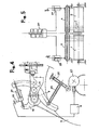
- the arrangement according to the invention illustrated in figure 1, comprises two twin beams 1 and 2, the slow rotation of which is controlled by two separate unwinders 3 and 4, and two separate yarn carriers 5 and 6, onto which press and partially wind the warp yarns f fed from the beams 1 and 2 and Leading to the Loom healds.
- the yarn carriers 5 and 6 consist of two hollow metal roLLers, mounted freely rotating and tilting on a bar 7 which is carried by two end Levers 8 and 9 and by a central lever 10, said tevers being mounted respectively on supports 12, 13 and 14 of the loom casing, so as to oscillate on a common axis 11.
- the two yarn carriers 5 and 6 are mounted on the bar 7 by way of ball joints 15 and 16 allowing the free rotation and inclination thereof; whereas, at their outward far ends said yarn carriers are mounted on supports 17 and 18 carried by the Levers 8 and 9, so as to oscillate with said Levers on the axis 11; also in this case the yarn carriers are mounted by way of ball joints 19 and 20, allowing the free rotation and inclination of the supports 17 and 18 in respect of the levers 8 and 9, and consequently the rotation of the yarn carriers and their inclination in respect of the bar 7.
- Figures 1 to 3 finally show sensors 23 and 24 (figures 2 and 3 showing only the sensor 24) which detect the oscillations of the levers 8 and 9 and/or of the supports 17 and 18, and accordingly operate the unwinders 3 and 4 (figures 2 and 3 showing only the unwinder 4). ;
- the supports 17 and/or 18 will oscillate, and said oscillations will be detected by the sensors 23 and/or 24 so as to suitably adjust the unwinders 3 and 4.
- These oscillations, opposed by the springs 22, are obtained thanks to the fact that the yarn carriers 5 and 6, and the supports 17 and 18, are mounted by way of ball joints (15, 16, and respectively, 19, 20).
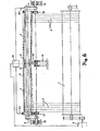
- FIGS 4 to 6 show some modified embodiments of the arrangement according to the invention.
- Figure 4 shows how the return means for the Levers 8 and 9 may comprise - instead of a spring 21 - a positive control, consisting of a pair of toggle-joint Levers 25 and 26 and of a cam 27 acting on said pair of Levers.
- the supports 17 and 18 (see figures 4 and 5) can be controlled by means of hydraulic cylinders 28 and 29, the action of which is balanced thanks to their connection to a central cylinder 30 which regulates the strength of said action. In this case, unwinding takes place merely thanks to the changes of inclination of the yarn carriers 5 and 6.
- FIG. 6 finaLLy shows the system according to the invention, applied in the case of using a single beam 1: there are again two yarn carriers 5 and 6, mounted as in the previous arrangement, and two sensors 23 and 24, the signals of which are caused to interact in an electronic circuit 31, so as to obtain signals for controlling the single unwinder 3 of the beam 1.
- This arrangement allows to operate with high warp yarn tensions.
Landscapes
- Engineering & Computer Science (AREA)
- Textile Engineering (AREA)
- Looms (AREA)
Applications Claiming Priority (2)
| Application Number | Priority Date | Filing Date | Title |
|---|---|---|---|
| IT8520983A IT1207056B (it) | 1985-05-31 | 1985-05-31 | Dispositivo svolgitore di subbi d'ordito gemelli in telai di tessitura. |
| IT2098385 | 1985-05-31 |
Publications (2)
| Publication Number | Publication Date |
|---|---|
| EP0204233A2 true EP0204233A2 (fr) | 1986-12-10 |
| EP0204233A3 EP0204233A3 (fr) | 1988-05-18 |
Family
ID=11174972
Family Applications (1)
| Application Number | Title | Priority Date | Filing Date |
|---|---|---|---|
| EP86107050A Ceased EP0204233A3 (fr) | 1985-05-31 | 1986-05-23 | Dispositif de déroulement pour les ensouples d'ourdissage doubles dans les métiers à tisser |
Country Status (5)
| Country | Link |
|---|---|
| US (1) | US4722368A (fr) |
| EP (1) | EP0204233A3 (fr) |
| JP (1) | JPS61282459A (fr) |
| ES (1) | ES8703543A1 (fr) |
| IT (1) | IT1207056B (fr) |
Cited By (2)
| Publication number | Priority date | Publication date | Assignee | Title |
|---|---|---|---|---|
| EP1020552A1 (fr) * | 1998-12-23 | 2000-07-19 | NUOVA VAMATEX S.p.A. | Porte-fils pour métiers à tisser |
| EP1020551A3 (fr) * | 1998-12-23 | 2000-08-02 | NUOVA VAMATEX S.p.A. | Métier à tisser avec ensouple à chaíne entraínée par deux actionneurs |
Families Citing this family (2)
| Publication number | Priority date | Publication date | Assignee | Title |
|---|---|---|---|---|
| EP0562214A1 (fr) * | 1992-03-27 | 1993-09-29 | Sulzer RàTi Ag | Métier à tisser avec des ensouples sectionnelles |
| BE1011184A3 (nl) * | 1997-05-28 | 1999-06-01 | Picanol Nv | Inrichting voor het bepalen van de kettingspanning. |
Family Cites Families (11)
| Publication number | Priority date | Publication date | Assignee | Title |
|---|---|---|---|---|
| US2539296A (en) * | 1949-04-28 | 1951-01-23 | Draper Corp | Warp letoff mechanism |
| US3147776A (en) * | 1960-03-23 | 1964-09-08 | Hofmann Gerhard | Pneumatic warp tensioning device for looms |
| FR1407185A (fr) * | 1964-06-17 | 1965-07-30 | Inst Textile De France | Dispositif de commande par mouvement rotatif à vitesse constante d'un dérouleur de fils de chaîne pour métier à tisser |
| IT999227B (it) * | 1972-11-29 | 1976-02-20 | Incotex Sa | Meccanismo di regolazione per svol gitori automatici di ordito con au tomatismo di messa a zero |
| CH623873A5 (fr) * | 1977-12-02 | 1981-06-30 | Sulzer Ag | |
| CH629549A5 (en) * | 1979-04-09 | 1982-04-30 | Grob Willy Ag | Positive warp let-off device |
| US4392516A (en) * | 1981-06-04 | 1983-07-12 | Burlington Industries, Inc. | Drive for loom easer bar |
| JPH0694614B2 (ja) * | 1983-02-25 | 1994-11-24 | 津田駒工業株式会社 | 織機の電動送り出し方法およびその装置 |
| JPS6052656A (ja) * | 1983-08-31 | 1985-03-25 | 日産テクシス株式会社 | 織機の経糸送出し装置 |
| DE3367635D1 (en) * | 1983-10-03 | 1987-01-02 | Rueti Ag Maschf | Warp let-off control mechanism for looms |
| CH664389A5 (de) * | 1984-10-16 | 1988-02-29 | Saurer Ag Adolph | Einrichtung zur steuerung der kettfadenspannung durch lageverschiebung eines streichbaumes an einer webmaschine. |
-
1985
- 1985-05-31 IT IT8520983A patent/IT1207056B/it active
-
1986
- 1986-05-23 EP EP86107050A patent/EP0204233A3/fr not_active Ceased
- 1986-05-23 US US06/866,788 patent/US4722368A/en not_active Expired - Fee Related
- 1986-05-30 JP JP61123882A patent/JPS61282459A/ja active Pending
- 1986-05-30 ES ES555521A patent/ES8703543A1/es not_active Expired
Cited By (2)
| Publication number | Priority date | Publication date | Assignee | Title |
|---|---|---|---|---|
| EP1020552A1 (fr) * | 1998-12-23 | 2000-07-19 | NUOVA VAMATEX S.p.A. | Porte-fils pour métiers à tisser |
| EP1020551A3 (fr) * | 1998-12-23 | 2000-08-02 | NUOVA VAMATEX S.p.A. | Métier à tisser avec ensouple à chaíne entraínée par deux actionneurs |
Also Published As
| Publication number | Publication date |
|---|---|
| ES8703543A1 (es) | 1987-02-16 |
| ES555521A0 (es) | 1987-02-16 |
| US4722368A (en) | 1988-02-02 |
| IT1207056B (it) | 1989-05-17 |
| IT8520983A0 (it) | 1985-05-31 |
| JPS61282459A (ja) | 1986-12-12 |
| EP0204233A3 (fr) | 1988-05-18 |
Similar Documents
| Publication | Publication Date | Title |
|---|---|---|
| US4240471A (en) | Loom back rest mechanism | |
| KR920002189B1 (ko) | 직기를 위한 개량된 날실장력장치 | |
| EP0204233A2 (fr) | Dispositif de déroulement pour les ensouples d'ourdissage doubles dans les métiers à tisser | |
| JPH0641847A (ja) | 部分経糸ビームを有する織機 | |
| US5615712A (en) | Technique for separating and tensioning warp threads in a face-to-face weaving machine | |
| US4690176A (en) | Back rest arrangement on a weaving machine | |
| US4403630A (en) | Apparatus for tensioning the warp thread sheet of a loom | |
| JP2693408B2 (ja) | 織機におけるたて糸の張り装置 | |
| JPH0849139A (ja) | 織機におけるたて糸の張り装置 | |
| EP0537111A1 (fr) | Dispositif pour détecter la tension des fils de chaîne dans un métier à tisser | |
| US5722464A (en) | Pile warp thread tension control apparatus for terry cloth weaving | |
| JP3875782B2 (ja) | 経糸テンショナを制御する装置及び同装置を備えた織機 | |
| EP0965552B1 (fr) | Dispositif pour surveiller la réserve de fil dans les fournisseurs de trame de métiers à tisser | |
| US6230754B1 (en) | Ground warp let-off tension device of a cloth movable type terry pile loom | |
| SE508390C2 (sv) | Torkvira för en pappersmaskin | |
| JPH05247772A (ja) | 織っている間に織物の端部に模様を付けるジャガード系 | |
| US3125128A (en) | Pfarrwaller | |
| US20060021667A1 (en) | Driving system for terry motion members in cloth-shifting-type pile loom | |
| EP1020552B1 (fr) | Porte-fils pour métiers à tisser | |
| SU1687666A1 (ru) | Механизм компенсации уточной нити дл бесчелночного ткацкого станка | |
| JPH09111599A (ja) | 織機のたて糸の非制御式張り装置 | |
| US5341851A (en) | Loom having at least two sectional warp beams | |
| EP0090249B1 (fr) | Ensouple de tissage avec barre de torsion à l'intérieur pour métiers à tisser | |
| JPS6317937B2 (fr) | ||
| JPH0210140Y2 (fr) |
Legal Events
| Date | Code | Title | Description |
|---|---|---|---|
| PUAI | Public reference made under article 153(3) epc to a published international application that has entered the european phase |
Free format text: ORIGINAL CODE: 0009012 |
|
| AK | Designated contracting states |
Kind code of ref document: A2 Designated state(s): AT BE CH DE FR GB LI LU NL SE |
|
| PUAL | Search report despatched |
Free format text: ORIGINAL CODE: 0009013 |
|
| RHK1 | Main classification (correction) |
Ipc: D03D 49/10 |
|
| AK | Designated contracting states |
Kind code of ref document: A3 Designated state(s): AT BE CH DE FR GB LI LU NL SE |
|
| 17P | Request for examination filed |
Effective date: 19880711 |
|
| 17Q | First examination report despatched |
Effective date: 19900307 |
|
| STAA | Information on the status of an ep patent application or granted ep patent |
Free format text: STATUS: THE APPLICATION HAS BEEN REFUSED |
|
| 18R | Application refused |
Effective date: 19910216 |
|
| RIN1 | Information on inventor provided before grant (corrected) |
Inventor name: PEZZOLI, LUIGI |