EP0204314B1 - Katalysator für die Wasserstoffbehandlung von Schwerölen - Google Patents
Katalysator für die Wasserstoffbehandlung von Schwerölen Download PDFInfo
- Publication number
- EP0204314B1 EP0204314B1 EP86107517A EP86107517A EP0204314B1 EP 0204314 B1 EP0204314 B1 EP 0204314B1 EP 86107517 A EP86107517 A EP 86107517A EP 86107517 A EP86107517 A EP 86107517A EP 0204314 B1 EP0204314 B1 EP 0204314B1
- Authority
- EP
- European Patent Office
- Prior art keywords
- catalyst
- carrier
- concentration
- metal
- center
- Prior art date
- Legal status (The legal status is an assumption and is not a legal conclusion. Google has not performed a legal analysis and makes no representation as to the accuracy of the status listed.)
- Expired - Lifetime
Links
Images



Classifications
-
- B—PERFORMING OPERATIONS; TRANSPORTING
- B01—PHYSICAL OR CHEMICAL PROCESSES OR APPARATUS IN GENERAL
- B01J—CHEMICAL OR PHYSICAL PROCESSES, e.g. CATALYSIS OR COLLOID CHEMISTRY; THEIR RELEVANT APPARATUS
- B01J23/00—Catalysts comprising metals or metal oxides or hydroxides, not provided for in group B01J21/00
- B01J23/16—Catalysts comprising metals or metal oxides or hydroxides, not provided for in group B01J21/00 of arsenic, antimony, bismuth, vanadium, niobium, tantalum, polonium, chromium, molybdenum, tungsten, manganese, technetium or rhenium
-
- B—PERFORMING OPERATIONS; TRANSPORTING
- B01—PHYSICAL OR CHEMICAL PROCESSES OR APPARATUS IN GENERAL
- B01J—CHEMICAL OR PHYSICAL PROCESSES, e.g. CATALYSIS OR COLLOID CHEMISTRY; THEIR RELEVANT APPARATUS
- B01J23/00—Catalysts comprising metals or metal oxides or hydroxides, not provided for in group B01J21/00
- B01J23/70—Catalysts comprising metals or metal oxides or hydroxides, not provided for in group B01J21/00 of the iron group metals or copper
- B01J23/76—Catalysts comprising metals or metal oxides or hydroxides, not provided for in group B01J21/00 of the iron group metals or copper combined with metals, oxides or hydroxides provided for in groups B01J23/02 - B01J23/36
- B01J23/84—Catalysts comprising metals or metal oxides or hydroxides, not provided for in group B01J21/00 of the iron group metals or copper combined with metals, oxides or hydroxides provided for in groups B01J23/02 - B01J23/36 with arsenic, antimony, bismuth, vanadium, niobium, tantalum, polonium, chromium, molybdenum, tungsten, manganese, technetium or rhenium
- B01J23/85—Chromium, molybdenum or tungsten
-
- B—PERFORMING OPERATIONS; TRANSPORTING
- B01—PHYSICAL OR CHEMICAL PROCESSES OR APPARATUS IN GENERAL
- B01J—CHEMICAL OR PHYSICAL PROCESSES, e.g. CATALYSIS OR COLLOID CHEMISTRY; THEIR RELEVANT APPARATUS
- B01J35/00—Catalysts, in general, characterised by their form or physical properties
- B01J35/30—Catalysts, in general, characterised by their form or physical properties characterised by their physical properties
- B01J35/31—Density
- B01J35/32—Bulk density
-
- B—PERFORMING OPERATIONS; TRANSPORTING
- B01—PHYSICAL OR CHEMICAL PROCESSES OR APPARATUS IN GENERAL
- B01J—CHEMICAL OR PHYSICAL PROCESSES, e.g. CATALYSIS OR COLLOID CHEMISTRY; THEIR RELEVANT APPARATUS
- B01J35/00—Catalysts, in general, characterised by their form or physical properties
- B01J35/60—Catalysts, in general, characterised by their form or physical properties characterised by their surface properties or porosity
- B01J35/61—Surface area
- B01J35/615—100-500 m2/g
-
- B—PERFORMING OPERATIONS; TRANSPORTING
- B01—PHYSICAL OR CHEMICAL PROCESSES OR APPARATUS IN GENERAL
- B01J—CHEMICAL OR PHYSICAL PROCESSES, e.g. CATALYSIS OR COLLOID CHEMISTRY; THEIR RELEVANT APPARATUS
- B01J35/00—Catalysts, in general, characterised by their form or physical properties
- B01J35/60—Catalysts, in general, characterised by their form or physical properties characterised by their surface properties or porosity
- B01J35/63—Pore volume
- B01J35/633—Pore volume less than 0.5 ml/g
-
- B—PERFORMING OPERATIONS; TRANSPORTING
- B01—PHYSICAL OR CHEMICAL PROCESSES OR APPARATUS IN GENERAL
- B01J—CHEMICAL OR PHYSICAL PROCESSES, e.g. CATALYSIS OR COLLOID CHEMISTRY; THEIR RELEVANT APPARATUS
- B01J35/00—Catalysts, in general, characterised by their form or physical properties
- B01J35/60—Catalysts, in general, characterised by their form or physical properties characterised by their surface properties or porosity
- B01J35/63—Pore volume
- B01J35/635—0.5-1.0 ml/g
-
- B—PERFORMING OPERATIONS; TRANSPORTING
- B01—PHYSICAL OR CHEMICAL PROCESSES OR APPARATUS IN GENERAL
- B01J—CHEMICAL OR PHYSICAL PROCESSES, e.g. CATALYSIS OR COLLOID CHEMISTRY; THEIR RELEVANT APPARATUS
- B01J35/00—Catalysts, in general, characterised by their form or physical properties
- B01J35/60—Catalysts, in general, characterised by their form or physical properties characterised by their surface properties or porosity
- B01J35/64—Pore diameter
- B01J35/647—2-50 nm
-
- B—PERFORMING OPERATIONS; TRANSPORTING
- B01—PHYSICAL OR CHEMICAL PROCESSES OR APPARATUS IN GENERAL
- B01J—CHEMICAL OR PHYSICAL PROCESSES, e.g. CATALYSIS OR COLLOID CHEMISTRY; THEIR RELEVANT APPARATUS
- B01J35/00—Catalysts, in general, characterised by their form or physical properties
- B01J35/60—Catalysts, in general, characterised by their form or physical properties characterised by their surface properties or porosity
- B01J35/66—Pore distribution
-
- B—PERFORMING OPERATIONS; TRANSPORTING
- B01—PHYSICAL OR CHEMICAL PROCESSES OR APPARATUS IN GENERAL
- B01J—CHEMICAL OR PHYSICAL PROCESSES, e.g. CATALYSIS OR COLLOID CHEMISTRY; THEIR RELEVANT APPARATUS
- B01J37/00—Processes, in general, for preparing catalysts; Processes, in general, for activation of catalysts
- B01J37/02—Impregnation, coating or precipitation
- B01J37/0201—Impregnation
- B01J37/0205—Impregnation in several steps
-
- C—CHEMISTRY; METALLURGY
- C10—PETROLEUM, GAS OR COKE INDUSTRIES; TECHNICAL GASES CONTAINING CARBON MONOXIDE; FUELS; LUBRICANTS; PEAT
- C10G—CRACKING HYDROCARBON OILS; PRODUCTION OF LIQUID HYDROCARBON MIXTURES, e.g. BY DESTRUCTIVE HYDROGENATION, OLIGOMERISATION, POLYMERISATION; RECOVERY OF HYDROCARBON OILS FROM OIL-SHALE, OIL-SAND, OR GASES; REFINING MIXTURES MAINLY CONSISTING OF HYDROCARBONS; REFORMING OF NAPHTHA; MINERAL WAXES
- C10G45/00—Refining of hydrocarbon oils using hydrogen or hydrogen-generating compounds
- C10G45/02—Refining of hydrocarbon oils using hydrogen or hydrogen-generating compounds to eliminate hetero atoms without changing the skeleton of the hydrocarbon involved and without cracking into lower boiling hydrocarbons; Hydrofinishing
- C10G45/04—Refining of hydrocarbon oils using hydrogen or hydrogen-generating compounds to eliminate hetero atoms without changing the skeleton of the hydrocarbon involved and without cracking into lower boiling hydrocarbons; Hydrofinishing characterised by the catalyst used
-
- B—PERFORMING OPERATIONS; TRANSPORTING
- B01—PHYSICAL OR CHEMICAL PROCESSES OR APPARATUS IN GENERAL
- B01J—CHEMICAL OR PHYSICAL PROCESSES, e.g. CATALYSIS OR COLLOID CHEMISTRY; THEIR RELEVANT APPARATUS
- B01J2235/00—Indexing scheme associated with group B01J35/00, related to the analysis techniques used to determine the catalysts form or properties
-
- B—PERFORMING OPERATIONS; TRANSPORTING
- B01—PHYSICAL OR CHEMICAL PROCESSES OR APPARATUS IN GENERAL
- B01J—CHEMICAL OR PHYSICAL PROCESSES, e.g. CATALYSIS OR COLLOID CHEMISTRY; THEIR RELEVANT APPARATUS
- B01J35/00—Catalysts, in general, characterised by their form or physical properties
- B01J35/30—Catalysts, in general, characterised by their form or physical properties characterised by their physical properties
- B01J35/396—Distribution of the active metal ingredient
Definitions
- the present invention relates to a catalyst for the hydrotreatment of heavy oils. More specifically, it retates to a hydro-treating catalyst for removing sulfur, nitrogen and metals such as nickel and vanadium contained in the heavy oils.
- This hydrotreatment is a process in which the material oil is catalytically treated under a hydrogen pressure in order to remove the sulfur and the nitrogen therefrom by converting them into hydrogen sulfide and ammonia, or to remove the metal content therefrom by depositing it on the catalyst.
- an indirect desulfurization has been particularly utilized to mainly treat vacuum gas oils, and thus the metal content in the material oil has been small.
- metals such as nickel, vanadium and the like increase in the residual oil, and in consequence, the residual oil has often been treated by a direct desulfurization.
- a problem of such a process is that pores in the catalyst are plugged with the metal in the oils and coke, so that the activity of the catalyst will be poor and the operation of the apparatus will be impeded. Accordingly, in order to keep the stable operation of the apparatus, it is necessary to develop a catalyst having a long life which can effectively remove the metals contained in the material heavier oils therefrom and which can maintain its activity for a long period.
- the catalysts for the hydrotreatment of the heavy oils are in the form of particles or extrudates each having a diameter of several millimeters to 1 cm.
- the catalysts are made by a solution impregnation method, which comprises dissolving a catalytically active component in a solvent, immersing a carrier into the resultant solution, taking out the carrier therefrom after a predetermined period, drying and then calcining it.
- the concentration of the active metal are uniform in the carrier or are high in the vicinity of the outside surface of the carrier.
- the metals in the heavy oils are deposited in the vicinity of the outside surface of the catalyst, so that pores in the catalyst are plugged therewith, with the result that an active sites in the catalyst are not be utilized sufficiently effectively.
- the inventors of the present application have conducted researches with the intention of solving the above mentioned problems, and as a result thereof, they have found that the metal present in heavy oils can be uniformly deposited in a catalyst by regulating a concentrative distribution of an active metal component for hydrogenation in a carrier, i.e., by establishing the regulation so that the concentration of the active metal may be low in the vicinity of the outside surface of the carrier and may become higher toward the center of the carrier, whereby the life of the catalyst is prolonged maintaining its activity, and the present invention has now been completed on the basis of such a knowledge.
- the present invention provides a catalyst for hydrotreatment of heavy oils, in which at least one active metal component for hydrogenation selected from the Groups Vb, Vlb and VIII of the periodic table is supported in a porous refractory carrier, the catalyst being characterized in that a distribution of the metal concentration in each catalyst satisfies the relation of Cr 1 ⁇ Cr 2 in the case of R 1 >R 2 in the sectional surface of said catalyst, wherein R i and R 2 represent ratios of distances r i and r 2 from the center of the sectional surface of catalyst to optional points therein, respectively, to a distance l from the aforesaid center to the outside surface of the catalyst, and Cr 1 and Cr 2 represent concentrations of the metal component at the points r 1 and r 2 .
- the catalyst of the present invention muy be prepared by supporting an active metal in a porous refractory carrier, the method comprising the steps of immersing the carrier into the following solution A, taking out it therefrom, and further immersing it into the following solution B, or after the immersion in the solution B, taking out it therefrom, and immersing it into the solution A again, so as to control a concentrative distribution of the active metal in the carrier:
- the catalyst of the present invention is characterized by the distribution of the hydrogenating active metal component concentration in the porous refractory carrier, i.e., as shown in Fig. 2, by the distribution of the metal component concentration which is getting higher from the outside surface toward the center of the catalyst.
- the activity of the catalyst in the vicinity of the outside surface of the catalyst can be inhibited, so that the adhesion and deposition of metals and coke can be reduced in the vicinity of the outside surface of the catalyst, with the result that the life of the catalyst can be prolonged.
- the catalyst as a method for measuring the distribution of the active component concentration in the catalys, there is an X-ray microanalysis method (EPMA).
- EPMA X-ray microanalysis method
- the catalyst when having the form of an extrudate, is cut at right angles to its outer peripheral surface, or when having the form of a sphere, it is cut passing through its center. Then, the exposed section of the catalyst is scanned by means of EPMA, thereby obtaining a drawing in which the desired concentrative distribution is shown.
- a catalyst in the case of having a columnal form, is cut at right angles to the outer peripheral surface thereof, or in the case of having a spherical form, it is cut passining through the center thereof, as shown in Figs. 1 (a) and 1 (b), respectively.
- the thus cut and exposed surface of the catalyst are called a sectional surface hereinafter.
- a concentration of metal components can be measured with a spot having a diameter of 10 microns on the sectional surface by means of EPMA. Further, this spot is scanned in a certain direction on the sectional surface in order to obtain a drawing in which the concentration of the metal components is shown. In the present invention, it is necessary to measure the concentration of the metal components in an axial direction passing through the center of the sectional surface, and its example is shown in Fig. 2.
- the concentration of the metal components at an optional point on the sectional surface of the catalyst can be sought.
- the ordinate represents a concentration C of the metal components
- a carrier used in the present invention is a refractory carrier, and in particular, a porous refractory inorganic oxide is preferred.
- a porous refractory inorganic oxide is preferred.
- an oxide of at least one selected from elements in Groups II, III and IV of the periodic table can be mentioned.
- preferable ones include silica, alumina, magnesia, zirconia, thoria, bo- ria, strontia and hafnia; more preferable ones.include alumina, silica-alumina, silica-magnesia and alumina-magnesia; and the most preferable oxide is alumina.
- alumina has a crystalline structure of 8, ⁇ , X the like.
- a diameter of this carrier is generally within the range of 0.1 to 10 mm, and in the case that the carrier is prepared by extrudation, it is usually in the range of 0.3 to 10mm.
- the shape of the carrier is sperical, it is preferably within the range of 0.1 to 5 mm.
- a surface area of the carrier is usually at least about 100 m2/g, and that an average pore diameter and a pore volume of the carrier is at least about 20 A (angstrom) or more and 0.4 cc/g, respectively.
- a metallic component to be supported in the carrier in the present invention is a metal having a hydrogenating activity.
- metal components include metallic elements in Groups Vb, Vlb and VIII of the periodic table.
- Group Vb include V, Nb and Ta;
- examples of Group Vlb include Cr, Mo and W;
- examples of VIII include Fe, Co, Ni, Pd and Pt.
- Ni, Co, Mo, V and W are preferred, and in the case of combinations, Ni-Mo, Co-Mo, Ni-V and Ni-Co-Mo are preferred.
- An amount of the active metal to be supported in the carrier is usually within the range of about 0.1 to about 25% by weight, preferably about 0.5 to about 20% by weight, in terms of a metallic element, based on the total weight of the catalyst.
- the concentration of each metallic component is also within the above mentioned range.
- the concentration of the coexistent metallic components is within the rage of 0.01 to 25% by weight, preferably 0.1 to 15% by weight.
- a carrier is immersed into a solution A containing an active metallic component at a temperature of 10 to 90 ° C, preferably room temperature to 50 ° C for a period of 1 minute to 1 week or so, preferably 30 minutes to 3 days.
- the carrier is taken out therefrom, and it is then immersed into a solution B at a temperature of 10 to 90 ° C, preferably at room temperature for a period of 30 seconds to 12 hours, preferably 1 minute from 3 hours.
- the carrier is immersed into the solution B at a temperature of 10 to 90 ° C, preferably room temperature to 50 ° C for 30 seconds to 12 hours, preferably 1 minute to 3 hours. After a predetermined period, th carrier is taken out therefrom, it is then immersed into the solution A containing the active metallic component an a temperature of 10 to 90°C, preferably ordinary temperature to 50°C for a period of 1 minute to 1 week, preferably 30 minutes to 3 days. After a predetermined period, the carrier is taken out therefrom. Then the carrier allowed to stand or heated at a temperature of 100 to 120 ° C for drying.
- the thus dried carrier is calcined preferably at a temperature of 500 to 600 ° C for a period of 2 to 6 hours in order to obtain the usable catalyst.
- a method disclosed in the specification of Japanese Patent Provisional Publication No. 252682/1985 of the same inventors as in the present application i.e., the method of immersing the carrier into a hydrophilic solvent (such as acetone) in order to remove water content therefrom.
- any compounds are usable in so far as they are water soluble metallic compounds, especially hydrochloride, nitrates and ammonium salts of these metals are preferably used.
- an anion e.g., a fluoride ion or chloride ion
- ammonium ion, nitrate ion, sulfate ion, hydroxyl ion, phosphate ion or borate ion which is present in the solutions A and B used in the present invention
- any compound is usable, in so far as it provides the above mentioned ion.
- these ion sources include acids, ammonia water and ammonium salts.
- organic acids used in the present invention include acetic acid, citric acid, tartaric acid, malic acid and the like.
- a concentration of each kind of ion is within the range of 0.05 to 10 mol/2, preferably 0.1 to 5 mol/i.
- water which is an example of the solution B there is preferably used water which has been purified by a distillation method, an ion exchange resin method or the like.
- a distribution of the active metal concentration in the carrier can be confirmed from the measurement by EPMA, as described above, and examples of the concentrative distribution which can be controlled in the present invention are shown in Fig. 9. That is, in a case 1 in this drawing, two kinds of active components A and B have high concentrations at the center of the carrier.
- the constitution of the case 1 can be prepared by immersing an alumina carrier into the solution A containing an active metal and an organic acid, and then immersing it into the solution B containing a mineral acid and ammonium fluoride.
- the concentration of the active component A alone is higher at the center of the carrier, and the active component B is substantially uniform therein.
- the constitution of the case 2 can be prepared by immersing the alumina carrier into the soultuion A and then immersing it into water which is the solution B.
- its specific surface area is within the range of 2 to 400 m 2 /g, preferably 100 to 300 m 2 /g; its bulk density is within the range of 0.3 to 1 g/m2, preferably 0.4 to 0.8 g/m8; its average pore volume is within the range of 0.1 to 4 ml/g, preferably 0.3 to 1.0 ml/g; and its average pore diameter is within the range of 50 to 500 A preferably 80 to 300 A.
- the pore diameter is within the range of 0 to 1,000 A, and it is most desirable that the pore volume of the pores the pore diameter of which is from 80 to 500 A occupies about 25 to about 70% of the total pore volume of the pores each having the pore diameter 0 to 1,000 A.
- a shape of the catalyst is not limited, and for example, the catalyst may have a shape of a columnal form having a diameter of about 0.5 to 2 mm and a length of about 0.5 to 2 cm, a spherical form having a deameter of about 0.5 to 4 mm, a tablet form, a three-leaf form, or a four-leaf form.
- Heavy oils referred to in this specification substantially contain distillation residue such as asphaltene, and examples of the heavy oils include crude oil, topped crude oil, residual oils from atmospheric distillation and vacuum distillation of the crude oil, deasphalting asphalt, liquefied oil of coal, and oils derived from shale oil, tar sand and gilsonite. These heavy oils contain 0.1 to 10 wt% of sulfur, 0.1 to 1 wt% of nitrogen, and 10 to 1,000 ppm (total amount of nickel and vanadium) of heavy metals such as nickel and vanadium.
- a temperature is within the range of 250 to 500 ° C, preferably 300 to 450 ° C; a pressure is within the range of 20 to 300 kg/cm 2 , preferably 70 to 200 kg/cm 2 ; a flow rate of a hydrogen gas is within the range of 250 to 2,500 Nm 3 /kl, preferably 500 to 2,000 Nm3/ke,(feed oil); and an LHSV is within the range of 0.1 to 5 hr -1 , preferably 0.5 to 3 hr -1 .
- the catalyst of the present invention even when it is used for a long period of time, the pores in the vicinity of the outside surface is not plugged, which fact allows oil molecules to diffuse the interior of the catalyst, with the result that the active sites in the catalyst can be utilized effectively.
- the same effect can be expected, even if the activity is low on the whole, but in this case, the activity of the catalyst is low, because the probability of allowing the invaded oil molecules to go out therefrom without reacting may be high.
- the concentration of the inside active metal is heightened, and thus almost all the oil molecules which have got into its interior can be converted in accordance with an internal diffusion. For these reasons, the activity of the catalyst does not deteriorate, i.e., its certain activity can be maintained.
- the life of the catalyst regarding the present invention can be prolonged more than conventional catalysts.
- contents of molybdenum, cobalt and nickel were 6.5 wt%, 1.2 wt% and 0.9 wt%, respectively.
- the catalyst was cut, and the sectional surface thereof was subjected to a linear analysis by means of EPMA.
- a pore volume of the catalyst grain was 0.65 ml/g; an average pore diameter was 130 A and a pore volume of the pores having a pore diameter of 80 to 500 A was 72.5% of the total volume of the pores having a pore diameter of 0 to 1,000 A.
- the catalyst grain was cut, and the sectional surface thereof was subjected to a linear analysis by means of EPMA.
- Cs/Cc ratios of Mo, Co and Ni were 1.67, 1.67 and 1.3, respectively.
- a pore volume of the catalyst grain was 0.63 me/g, an average pore diameter was 132 A, and a pore volume of the pores having a pore diameter of 80 to 500 A was 71.5% of the total volume of the pores having a pore diameter of 0 to 1,000 A.
- the catalyst was cut, and the sectional surface thereof was subjected to a linear analysis by means of EPMA.
- a pore volume of the catalyst was 0.62 ml/g; an average pore diameter was 131 A; and a pore volume of the pores having a pore diameter of 80 to 500 A was 72.0% of the total volume of the pores having a pore diameter of 0 to 1,000 A.
- aqueous solution containing 8 wt% of Mo and 2 wt% of Co was prepared by using ammonium molybdate and cobalt nitrate. Citric acid equimolar with Mo was dissolved in the above prepared aqueous soluion to form a solution A1, and extruded alumina carrier grains each having a diameter of 1 mm were immersed into the solution A1 at room temperature for 3 hours. Afterward, the carrier was taken out therefrom and drained sufficiently, and it was then immersed into a solution B1 containing 1.0 mol/£ of ammonium fluoride and 1.0 mol/£ of HCl for 10 minutes.
- the thus treated carrier was taken out therefrom and drained, and was further immersed into acetone for 30 minutes.
- the acetone here used was that which had been circulated through a dehydrating agent.
- the carrier taken out therefrom was allowed to stand at room temperature for 30 minutes and was then calcined at 550 ° C for 3 hours in order to prepare a catalyst, which was named catalyst 1.
- Example 2 As the solution A, the solution A1 of Example 2 was used, and as the solution B, water was employed. The same procedure as in Example 2 was repeated to prepare a catalyst, which was named a catalyst 2.
- aqueous solution containing 8 wt% of Mo was prepared from ammonium molybdate, and the prepared solution was named a solution A2. Further, a 1.0 mol/£ ammonium fluoride solution was named a solution B2.
- Example 2 The same procedure as in Example 2 was repeated with the exception that the solutions A1 and B1 were replaced with the solutions A2 and B2 just described, in order to prepare a catalyst, which was named a catalyst 3.
- active metal sources there were employed ammonium metavanadate, ammonium paratungstate, ammonium molybdate, feric nitrate, nickel nitrate and cobalt nitrate, and the same procesure as in Example 2 was repeated in the combinations of Mo-Ni, Mo-Fe, Mo-Ni-Co, W-Ni and V-Ni in order to prepare catalysts, which were name catalyst 4 to 8.
- Mo, W and V were each contained at a concentration of 8 wt% and the others were each contained at a concentration of 2 wt% in solutions.
- aqueous solution containing 5 wt% of Mo and 0.5 wt% of Co was prepared from ammonium molybdate and cobalt nitrate.
- the same alumina carrier as in Example 2 was immersed into the above prepared aqueous solution at room temperature for 3 hours, and it was then taken out therefrom and was drained. Afterward, the carrier was treated with acetone in the same manner as in Example 2, and the subsequent procedures were carried out as in Example 2, in order to prepare a catalyst, which was named a catalyst 9.
- the catalyst 9 of Comparative Example 3 was prepared so as to conform its metal concentrations to those of the catalyst 1 of Example 2.
- the concentrations of Mo and Co are highest at the center of each catalyst, as shown in Fig. 10.
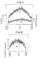
- the concentration of Co alone is higher at the center thereof as shown in Fig. 11, and the Mo concentration is distributed substantially constantly therein.
- the catalyst prepared in Example 4 can have a higher Mo concentration at the center thereof as shown in Fig. 12, though Mo is only used.
- every metal concentration is higher at the center of each catalyst, and they are indicative of about the same distribution as in Fig. 12.
- the method of the present invention permits controlling the distribution of the supported metals in the carrier.
- a hydrotreatment of heavy oil was carried out by the use of a fixed-bed type reactor. That is, the reactor of 20 mm in inner diameter and 2,000 mm in length was filled with 300 g of a catalyst, and the hydrotreatment was accomplished under the following reaction conditions:
- Feed was Arabianlight vacuum residual oil. Properties of the oil were as follows:
- Example 1 Comparative Examples 1 and 2 were named A, B and C, respectively.
- the catalyst A is concerned with the present invention, the catalyst B has high concentrations of the active metals, and the catalyst C has the same concentrations of the active metals as in the catalyst A. However, the catalysts B and C are different from the catalyst A in a distribution of the active metal concentration.
- the desulfurization rate of the catalyst A is a little lower at an early stage but is stable for a long period of time.
- values of the catalysts A, B and C all are close to one another, but it is apparent that the catalyst A of the present invention is still excellent toward the end of a run time of the oil.
- the metal removal rate shown in Fig. 5 the three kinds of catalysts A, B and C are not so different in initial activity, but the metal removal rate of the catalysts B and C decreases gradually with time. On the contrary, in the catalyst A regarding the present invention, the metal removal rate scarcely diminishes and its constant effect is maintained.
- a hydrotreatment of heavy oil was carried out with the catalysts 1 and 9 by the use of a fixed-bed type reactor.
Landscapes
- Chemical & Material Sciences (AREA)
- Engineering & Computer Science (AREA)
- Organic Chemistry (AREA)
- Chemical Kinetics & Catalysis (AREA)
- Materials Engineering (AREA)
- Oil, Petroleum & Natural Gas (AREA)
- General Chemical & Material Sciences (AREA)
- Catalysts (AREA)
Claims (2)
daß in jedem Katalysator eine Konzentrationsverteilung des Metalls in einer Schnittfläche des Katalysators die Bedingung erfüllt, daß Cri, < Cr2 ist, wenn R1 > R2 ist, wobei R1 und R2 die Verhälnisse zwischen den Abständen r1 bzw. r2 vom Mittelpunkt der Schnittfläche des Katalysators zu beliebigen Punkten darin zum Abstand ℓ des Mittelpunktes von des äußeren Oberfläche des Katalysators bezeichnen und wobei Cri und Cr2 die Konzentrationen der Metallkomponente an jenen Punkten ri und r2 sind.
daß die Metallkomponente zumindest ein Metall aus der Nickel, Kobalt, Molybdän, Vanadium und Wolfram enthaltenden Gruppe ist.
Applications Claiming Priority (4)
| Application Number | Priority Date | Filing Date | Title |
|---|---|---|---|
| JP60121741A JPS61283351A (ja) | 1985-06-05 | 1985-06-05 | 重質油の水素化処理触媒 |
| JP121741/85 | 1985-06-05 | ||
| JP38351/86 | 1986-02-25 | ||
| JP61038351A JPS62197153A (ja) | 1986-02-25 | 1986-02-25 | 重質油水素化触媒の製造法 |
Publications (3)
| Publication Number | Publication Date |
|---|---|
| EP0204314A2 EP0204314A2 (de) | 1986-12-10 |
| EP0204314A3 EP0204314A3 (en) | 1988-01-07 |
| EP0204314B1 true EP0204314B1 (de) | 1990-11-14 |
Family
ID=26377587
Family Applications (1)
| Application Number | Title | Priority Date | Filing Date |
|---|---|---|---|
| EP86107517A Expired - Lifetime EP0204314B1 (de) | 1985-06-05 | 1986-06-03 | Katalysator für die Wasserstoffbehandlung von Schwerölen |
Country Status (3)
| Country | Link |
|---|---|
| US (1) | US4760045A (de) |
| EP (1) | EP0204314B1 (de) |
| DE (1) | DE3675582D1 (de) |
Cited By (3)
| Publication number | Priority date | Publication date | Assignee | Title |
|---|---|---|---|---|
| CN104667956A (zh) * | 2013-11-26 | 2015-06-03 | 中国石油化工股份有限公司 | 一种烃油加氢改质催化剂及其制备方法 |
| US10252255B2 (en) | 2014-12-10 | 2019-04-09 | Petrochina Company Limited | Method for preparing noble metal hydrogenation catalyst, noble metal hydrogenation catalyst and use thereof |
| US10258965B2 (en) | 2014-12-10 | 2019-04-16 | Petrochina Company Limited | Sulfur-resistant catalyst for aromatics saturated hydrogenation and preparation method thereof |
Families Citing this family (27)
| Publication number | Priority date | Publication date | Assignee | Title |
|---|---|---|---|---|
| GB8620982D0 (en) * | 1986-08-29 | 1986-10-08 | Shell Int Research | Catalyst preparation |
| JPH0811184B2 (ja) * | 1987-02-06 | 1996-02-07 | 日本石油株式会社 | 重質油の水素化処理触媒 |
| US5047142A (en) * | 1988-05-13 | 1991-09-10 | Texaco Inc. | Catalyst composition and method for hydroprocessing petroleum feedstocks |
| JP3244693B2 (ja) * | 1990-10-17 | 2002-01-07 | 住友金属鉱山株式会社 | 炭化水素油の水素化処理用触媒の製造方法 |
| CA2079924A1 (en) * | 1991-10-18 | 1993-04-19 | Kazushi Usui | Catalyst composition for hydrotreating of hydrocarbon oils and process for manufacturing the same |
| JP2000246109A (ja) * | 1999-02-26 | 2000-09-12 | Japan Energy Corp | 水素化精製処理用触媒、水素化精製処理方法及び触媒の製造方法 |
| US6383974B1 (en) | 1997-08-26 | 2002-05-07 | Japan Energy Corporation | Hydrorefining catalyst and method for manufacturing hydrorefining catalyst |
| CN1102448C (zh) * | 1999-09-29 | 2003-03-05 | 中国石油化工集团公司 | 一种具有不均匀活性金属分布催化剂的制备方法 |
| JP2001104790A (ja) * | 1999-10-07 | 2001-04-17 | Tonengeneral Sekiyu Kk | 水素化処理用触媒およびそれを用いる炭化水素油の水素化処理方法 |
| US6759364B2 (en) | 2001-12-17 | 2004-07-06 | Shell Oil Company | Arsenic removal catalyst and method for making same |
| TW200513320A (en) | 2003-06-16 | 2005-04-16 | Shell Int Research | A process and catalyst for the selective hydrogenation of diolefins contained in an olefin containing stream and for the removal of arsenic therefrom and a method of making such catalyst |
| EP1810751A1 (de) * | 2006-01-20 | 2007-07-25 | Universität Karlsruhe (TH) | Verfahren zur Herstellung eines eisenhaltigen SCR-Katalysators |
| CN101376106B (zh) * | 2007-08-31 | 2010-12-22 | 中国石油化工股份有限公司 | 一种重油加氢处理催化剂及其制备方法 |
| CN102861598B (zh) * | 2011-07-07 | 2015-08-26 | 中国石油化工股份有限公司 | 活性金属组分非均匀分布的含氟加氢催化剂及其制备 |
| CN103374387B (zh) * | 2012-04-13 | 2015-07-29 | 中国石油化工股份有限公司 | 一种镍和钒含量高的重油加氢处理方法 |
| CN103374388B (zh) * | 2012-04-13 | 2015-07-29 | 中国石油化工股份有限公司 | 一种铁和钙含量高的重质油的加氢处理方法 |
| CN103374389B (zh) * | 2012-04-13 | 2015-07-29 | 中国石油化工股份有限公司 | 一种铁和钙含量高的重质油的加氢处理方法 |
| CN103801403B (zh) * | 2012-11-08 | 2016-05-18 | 中国石油化工股份有限公司 | 一种加氢处理催化剂及其制备方法 |
| CN103801313B (zh) * | 2012-11-08 | 2016-06-29 | 中国石油化工股份有限公司 | 一种馏分油加氢处理催化剂及其制备方法 |
| AU2013344232B2 (en) * | 2012-11-08 | 2016-10-13 | China Petroleum & Chemical Corporation | Hydrogenation catalyst and manufacturing method therefor and use thereof |
| CN103801348B (zh) * | 2012-11-08 | 2016-03-02 | 中国石油化工股份有限公司 | 一种烃油加氢处理催化剂及其制备方法 |
| CN104293380B (zh) * | 2013-07-18 | 2016-02-24 | 中国石油化工股份有限公司 | 一种劣质重油的加氢处理方法 |
| CN104588031B (zh) * | 2013-10-31 | 2017-01-11 | 中国石油化工股份有限公司 | 馏分油加氢处理催化剂及其制备方法 |
| CN104667960B (zh) * | 2013-11-26 | 2017-04-12 | 中国石油化工股份有限公司 | 柴油加氢改质催化剂及其制备方法 |
| CN104667962B (zh) * | 2013-11-26 | 2017-04-12 | 中国石油化工股份有限公司 | 柴油加氢改质催化剂及其制法 |
| CN104667959B (zh) * | 2013-11-26 | 2017-03-22 | 中国石油化工股份有限公司 | 一种柴油加氢改质催化剂及其制备方法 |
| CN113042021B (zh) * | 2019-12-27 | 2023-05-26 | 中国石油化工股份有限公司 | 一种沸腾床加氢催化剂及其制备方法 |
Citations (1)
| Publication number | Priority date | Publication date | Assignee | Title |
|---|---|---|---|---|
| EP0160475A2 (de) * | 1984-04-25 | 1985-11-06 | Toa Nenryo Kogyo Kabushiki Kaisha | Wasserstoffbehandlungskatalysator und Verfahren zu dessen Herstellung |
Family Cites Families (3)
| Publication number | Priority date | Publication date | Assignee | Title |
|---|---|---|---|---|
| US2915478A (en) * | 1955-12-05 | 1959-12-01 | Sinclair Refining Co | Preparation of a cobalt oxide-molybdenum oxide-alumina catalyst |
| FR1383749A (fr) * | 1962-04-20 | 1965-01-04 | Universal Oil Prod Co | Produit composite catalytique, procédé pour sa préparation et ses applications, en particulier à la conversion de gaz de rebut |
| US4225421A (en) * | 1979-03-13 | 1980-09-30 | Standard Oil Company (Indiana) | Process for hydrotreating heavy hydrocarbons |
-
1986
- 1986-06-03 US US06/870,224 patent/US4760045A/en not_active Expired - Lifetime
- 1986-06-03 DE DE8686107517T patent/DE3675582D1/de not_active Expired - Lifetime
- 1986-06-03 EP EP86107517A patent/EP0204314B1/de not_active Expired - Lifetime
Patent Citations (1)
| Publication number | Priority date | Publication date | Assignee | Title |
|---|---|---|---|---|
| EP0160475A2 (de) * | 1984-04-25 | 1985-11-06 | Toa Nenryo Kogyo Kabushiki Kaisha | Wasserstoffbehandlungskatalysator und Verfahren zu dessen Herstellung |
Cited By (4)
| Publication number | Priority date | Publication date | Assignee | Title |
|---|---|---|---|---|
| CN104667956A (zh) * | 2013-11-26 | 2015-06-03 | 中国石油化工股份有限公司 | 一种烃油加氢改质催化剂及其制备方法 |
| CN104667956B (zh) * | 2013-11-26 | 2017-02-15 | 中国石油化工股份有限公司 | 一种烃油加氢改质催化剂及其制备方法 |
| US10252255B2 (en) | 2014-12-10 | 2019-04-09 | Petrochina Company Limited | Method for preparing noble metal hydrogenation catalyst, noble metal hydrogenation catalyst and use thereof |
| US10258965B2 (en) | 2014-12-10 | 2019-04-16 | Petrochina Company Limited | Sulfur-resistant catalyst for aromatics saturated hydrogenation and preparation method thereof |
Also Published As
| Publication number | Publication date |
|---|---|
| DE3675582D1 (de) | 1990-12-20 |
| US4760045A (en) | 1988-07-26 |
| EP0204314A2 (de) | 1986-12-10 |
| EP0204314A3 (en) | 1988-01-07 |
Similar Documents
| Publication | Publication Date | Title |
|---|---|---|
| EP0204314B1 (de) | Katalysator für die Wasserstoffbehandlung von Schwerölen | |
| US5399259A (en) | Hydroconversion process employing catalyst with specified pore size distribution | |
| EP1567617B1 (de) | Hydroprocessing von kohlenwasserstoff mittels einer mischung von katalysatoren | |
| US5514273A (en) | Hydroconversion process employing catalyst with specified pore size distribution | |
| KR100209814B1 (ko) | 수소화처리 촉매조성물, 그 제조방법 및 용도 | |
| US4861746A (en) | Catalyst for hydrotreating heavy hydrocarbon oils and a method of preparing the catalyst | |
| US7922894B2 (en) | HPC process using a mixture of catalysts | |
| JP2631712B2 (ja) | 重質炭化水素油の水素化処理触媒組成物ならびにそれを用いる水素化処理方法 | |
| JPS6326157B2 (de) | ||
| US4613425A (en) | Process for hydrotreating heavy hydrocarbon oils | |
| EP1567262B1 (de) | Hydroprocessing von schweren kohlenwasserstoffen mittels einer mischung von katalysatoren | |
| EP0016599B1 (de) | Hydrobehandlung eines Kohlenwasserstoffstroms zur Entfernung von Stickstoff und Schwefel und bei dieser Hydrobehandlung angewandter Katalysator | |
| EP1392798B1 (de) | Zweistufiges kohlenwasserstoffumwandlungsverfahren | |
| EP1392800B1 (de) | Zweistufiges hydrobehandlungsverfahren für schweröle | |
| EP0349223A1 (de) | Hydrierungskatalysator, seine Herstellung und seine Verwendung | |
| US4485006A (en) | Start-up method for a hydrorefining process | |
| CN100469440C (zh) | 一种加氢催化剂及其制备方法 | |
| US8012343B2 (en) | Heavy feed HPC process using a mixture of catalysts | |
| EP1052015A1 (de) | Katalysator zur hydrobehandlung von schweröl, träger für den katalysator, verfahren zur herstellung des katalysators | |
| DD140894A5 (de) | Verfahren zur hydrobehandlung von schweren kohlenwasserstoffstroemen | |
| EP0112667B1 (de) | Wasserstoffumwandlungskatalysator und -verfahren | |
| JPWO2000051730A1 (ja) | 水素化精製処理用触媒、水素化精製処理方法及び触媒の製造方法 | |
| JP3221705B2 (ja) | 炭化水素油の水素化処理用触媒組成物の製造法 | |
| JPH0550341B2 (de) | ||
| JPS59150537A (ja) | 水素化処理用触媒および炭化水素の水素化処理方法 |
Legal Events
| Date | Code | Title | Description |
|---|---|---|---|
| PUAI | Public reference made under article 153(3) epc to a published international application that has entered the european phase |
Free format text: ORIGINAL CODE: 0009012 |
|
| AK | Designated contracting states |
Kind code of ref document: A2 Designated state(s): DE FR GB NL |
|
| PUAL | Search report despatched |
Free format text: ORIGINAL CODE: 0009013 |
|
| AK | Designated contracting states |
Kind code of ref document: A3 Designated state(s): DE FR GB NL |
|
| 17P | Request for examination filed |
Effective date: 19880613 |
|
| 17Q | First examination report despatched |
Effective date: 19890505 |
|
| GRAA | (expected) grant |
Free format text: ORIGINAL CODE: 0009210 |
|
| AK | Designated contracting states |
Kind code of ref document: B1 Designated state(s): DE FR GB NL |
|
| REF | Corresponds to: |
Ref document number: 3675582 Country of ref document: DE Date of ref document: 19901220 |
|
| ET | Fr: translation filed | ||
| PLBI | Opposition filed |
Free format text: ORIGINAL CODE: 0009260 |
|
| 26 | Opposition filed |
Opponent name: AKZO N.V. Effective date: 19910814 |
|
| NLR1 | Nl: opposition has been filed with the epo |
Opponent name: AKZO N.V. |
|
| PGFP | Annual fee paid to national office [announced via postgrant information from national office to epo] |
Ref country code: DE Payment date: 19940325 Year of fee payment: 9 |
|
| PGFP | Annual fee paid to national office [announced via postgrant information from national office to epo] |
Ref country code: FR Payment date: 19940330 Year of fee payment: 9 |
|
| PLAB | Opposition data, opponent's data or that of the opponent's representative modified |
Free format text: ORIGINAL CODE: 0009299OPPO |
|
| PGFP | Annual fee paid to national office [announced via postgrant information from national office to epo] |
Ref country code: GB Payment date: 19940613 Year of fee payment: 9 |
|
| PGFP | Annual fee paid to national office [announced via postgrant information from national office to epo] |
Ref country code: NL Payment date: 19940630 Year of fee payment: 9 |
|
| R26 | Opposition filed (corrected) |
Opponent name: AKZO NOBEL N.V. Effective date: 19910814 |
|
| PG25 | Lapsed in a contracting state [announced via postgrant information from national office to epo] |
Ref country code: GB Effective date: 19950603 |
|
| APAC | Appeal dossier modified |
Free format text: ORIGINAL CODE: EPIDOS NOAPO |
|
| RDAG | Patent revoked |
Free format text: ORIGINAL CODE: 0009271 |
|
| STAA | Information on the status of an ep patent application or granted ep patent |
Free format text: STATUS: PATENT REVOKED |
|
| GBPC | Gb: european patent ceased through non-payment of renewal fee |
Effective date: 19950603 |
|
| 27W | Patent revoked |
Effective date: 19951206 |
|
| NLV4 | Nl: lapsed or anulled due to non-payment of the annual fee |
Effective date: 19960101 |
|
| APAH | Appeal reference modified |
Free format text: ORIGINAL CODE: EPIDOSCREFNO |