EP0204608A1 - Support de câbles pour poteau électrique - Google Patents
Support de câbles pour poteau électrique Download PDFInfo
- Publication number
- EP0204608A1 EP0204608A1 EP86401077A EP86401077A EP0204608A1 EP 0204608 A1 EP0204608 A1 EP 0204608A1 EP 86401077 A EP86401077 A EP 86401077A EP 86401077 A EP86401077 A EP 86401077A EP 0204608 A1 EP0204608 A1 EP 0204608A1
- Authority
- EP
- European Patent Office
- Prior art keywords
- shell
- post
- cable support
- cable
- support according
- Prior art date
- Legal status (The legal status is an assumption and is not a legal conclusion. Google has not performed a legal analysis and makes no representation as to the accuracy of the status listed.)
- Granted
Links
Images

Classifications
-
- H—ELECTRICITY
- H02—GENERATION; CONVERSION OR DISTRIBUTION OF ELECTRIC POWER
- H02G—INSTALLATION OF ELECTRIC CABLES OR LINES, OR OF COMBINED OPTICAL AND ELECTRIC CABLES OR LINES
- H02G7/00—Overhead installations of electric lines or cables
- H02G7/20—Spatial arrangements or dispositions of lines or cables on poles, posts or towers
Definitions
- the present invention relates to a cable support for an electric pole, comprising a body of insulating material comprising a core on which are mounted individual cable supports, the cable support further comprising means for attaching the body to one end of a post, while fixing means between the individual cable supports and the core are embedded in a stuffing material.
- Such a cable support is known from FR-A-1035391.
- Insulating supports of this kind attached to the end of a post, have the advantage of eliminating the need for individual insulators and of allowing the manufacture of these supports independently of the post.
- the body of insulating material appears expensive and difficult to produce because it requires a large mass of plastic material with high mechanical strength characteristics, resistance to the formation of arcs, resistance to aging, etc.
- the object of the present invention is to provide a more economical cable support.
- the cable support is characterized in that the core is delimited externally by a substantially rigid shell to which the individual cable supports are fixed, and in that the core is coated by an insulating skin with interposition stuffing material.
- the core, and in particular the shell ensuring a significant part of the mechanical strength of the assembly are protected by the skin. They do not need any particular resistance to aging by contact with the external environment, nor any particular resistance to the formation of arcs. It is the skin that performs these functions.
- the stuffing material not only protects and if necessary locks the fixing of the individual supports, but also attenuates the roughness resulting from this fixing on the shell, and therefore allows the skin to be everywhere in close contact with the sub-material adjacent, without separation.
- the stuffing material has, in contact with the skin, a corrugated surface defining corrugations corresponding to the outer surface of the skin.
- the skin has a wavy shape lengthening the arc path between two individual supports.
- the shell can be frustoconical.
- the individual supports may include a base plate glued against the shell, while fibers may be wrapped around the base plate and the shell to strengthen the bond.
- the individual cable supports each comprise a rod extending radially through the shell in an insulating support tube interposed between an individual cable support shoulder and a nut or the like resting on a flange of the tube itself pressed against the outer surface of the shell opposite the shoulder, which is adjacent to a head of the individual support.
- the means for supporting the body at one end of a post comprise an annular spacer fitted with the shell.
- the means for attaching the central body make it possible to orient the cable support on the end of the post, around the axis of the post.
- the means for attaching the central body make it possible to orient the cable support on the end of the post, around the axis of the post.
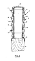
- the cable support for an electric pole comprises a central body generally designated in (1), on which are mounted individual cable supports (2, 3, 4), and means formed by a spacer (5) to connect the central body (1) to the upper end of a post (6).
- the central body (1) comprises a hollow central shell (7) closed at its upper part, made of filamentary material embedded in a resin.
- the central structure - (7) is, for example, produced by filament winding on a mandrel, preferably a man frustoconical drin with circular base.
- the technique of producing a hollow body by filament winding is in itself well known and it is therefore not necessary to give a detailed description.
- the fibers of the filamentary material extend in a general tangential direction forming an acute angle (not straight) with the axis of the shell 7.
- the shell can be reinforced, by longitudinal fibers, also embedded in the resin. These longitudinal fibers are, for example, part of a fabric placed around the shell between two layers of filament winding.
- the individual cable support (2) is fixed to the upper part of the cable support, which makes it possible to reduce the problems of torsion on the central shell and, in the case of '' a support of three cables as illustrated, to distribute the individual cable supports symmetrically on the central body.
- the individual cable support (2) has at its lower part a base plate (8) glued to the central structure (7).
- the individual cable support (3) comprises a base plate (10) substantially matching the shape of the lateral surface of the shell (7) and glued to it.
- fibers (11) are preferably wound around the shell (7) and the plate (10) after the latter has been placed.
- the individual cable support (4) comprises a rod (12), integral with the support head (13), and extending transversely to the shell (7) in an insulating support tube (14) comprising a flange 15) supported on the outer surface of the shell 7.
- the rod (12) is threaded and is held in place by a nut (16) which rests on the flange ( 15) and clamps the tube (14) against a flange - (28), forming a shoulder, which the rod (12) has on the outside of the shell (7) on the side of the head (13).
- the length of the tube (14) is preferably equal to the transverse dimension of the shell (7), so that the tightening of the nut (16) allows the individual cable support (4) to be firmly fixed without exerting crush stress on the hull - (7).
- the shell (7) is covered with a stuffing resin (17) having an external surface (18) forming undulations.
- the stuffing resin thus creates an increased arc path between the individual cable supports.
- the stuffing resin (17) is covered with a skin (19), preferably silicone resin, which protects the central body against electric arcs, against aging by ultraviolet rays and against the penetration of water.
- the central body (1) In order to increase the rigidity of the central body (1), it is preferably filled, at least over part of its height, with a core material - (20), for example an expanded resin.
- a core material - (20) for example an expanded resin.
- the spacer (5) comprises an annular skirt - (21) whose external dimension is substantially equal to the internal dimension of the shell (7) whose open lower end is fitted and fixed, for example glued, on the annular skirt - (21). At its lower part, the spacer (5) comprises a part (22) in the shape of a tulip ensuring a connection with the electric pole (6).
- the electric pole (6) is a hollow pole and the lower part of the spacer (5) preferably has a double wall enclosing the electric pole (6) inside and inside. outside.
- Figure (2) illustrates another embodiment of the invention in which the central structure (7) is cylindrical and closed at its upper part by a plug (23).
- the individual cable supports (2, 3, 4), shown diagrammatically, are this time distributed -only on the sides of the central body (1).
- the supports 2, 3, 4 are fixed according to one of the choice of fixing methods represented in FIG. 1.
- the shell (7) is covered with a stuffing resin (17), itself covered with a skin of silicone resin (19).
- the post (6) is a wooden post and the lower part of the spacer (5) has a single wall fitting onto the outside surface of the post (6).
- the spacer can be arranged in the manner of a sleeve outside the central body and the post.
- the embodiments described in detail each time include a spacer (5), provision can be made to directly fit the central body (1) onto the post (6).
- the body central (1) may have a non-circular cross section, for example a cross section adapted to the cross section of the post on which the central structure is to be mounted.
Landscapes
- Installation Of Indoor Wiring (AREA)
- Suspension Of Electric Lines Or Cables (AREA)
- Clamps And Clips (AREA)
- Insertion, Bundling And Securing Of Wires For Electric Apparatuses (AREA)
- Insulators (AREA)
- Supports For Pipes And Cables (AREA)
- Flexible Shafts (AREA)
- Insulating Bodies (AREA)
- Insulated Conductors (AREA)
Abstract
Description
- La présente invention concerne un support de câbles pour poteau électrique, comportant un corps en matériau isolant comprenant une âme sur laquelle sont montés des supports de câble individuels, le support de câbles comprenant en outre des moyens pour rapporter le corps à une extrémité d'un poteau, tandis que des moyens de fixation entre les supports de câble individuels et l'âme sont noyés dans une matière de bourrage.
- Un tel support de câbles est connu d'après le FR-A-1035391. Des supports isolants de ce genre, rapportés à l'extrémité d'un poteau, ont l'avantage de supprimer la nécessité des isolateurs individuels et de permettre la fabrication de ces supports indépendamment du poteau.
- Cependant, le corps en matériau isolant appa- rait coûteux et difficile à réaliser car il nécessite une masse importante de matière plastique à hautes caractéristiques de résistance mécanique, résistance à la formation des arcs, résistance au vieillissement etc.
- Le but de la présente invention est de proposer un support de câbles plus économique. Suivant l'invention, le support de câbles est caractérisé en ce que l'âme est délimitée extérieurement par une coque sensiblement rigide à laquelle sont fixés les supports de câble individuels, et en ce que l'âme est revêtue par une peau isolante avec interposition de la matière de bourrage.
- Ainsi l'âme, et notamment la coque assurant une part importante de la résistance mécanique de l'ensemble sont protégées par la peau. Elles n'ont pas besoin d'une résistance particulière au vieillissement par contact avec le milieu extérieur, ni d'une résistance particulière à la formation des arcs. C'est la peau qui assure ces fonctions. La matière de bourrage non seulement protège et le cas échéant verrouille la fixation des supports individuels, mais en outre atténue les aspérités résultant de cette fixation sur la coque, et permet donc à la peau d'être partout en contact étroit avec la matière sous-jacente, sans décollement.
- De préférence, la matière de bourrage a, en contact avec la peau, une surface ondulée définissant des ondulations correspondantes à la surface extérieure de la peau. Ainsi, la peau a une forme ondulée allongeant le chemin d'arc entre deux supports individuels.
- La coque peut être tronconique. Ainsi, il est possible de monter le même support de câbles sur des poteaux de dimensions variées en sectionnant le corps central à un niveau où celui-ci présente une dimension transversale correspondant à la dimension du poteau sur lequel il doit être monté.
- Les supports individuels peuvent comprendre une plaque de base collée contre la coque, tandis que des fibres peuvent être enroulées autour de la plaque de base et de la coque pour renforcer la liaison.
- Selon un autre mode de réalisation, les supports de câble individuels comprennent chacun une tige s'étendant radialement à travers la coque dans un tube support isolant interposé entre un épaulement de support de câble individuel et un écrou ou analogue s'appuyant sur une collerette du tube elle-même appuyée contre la surface extérieure de la coque à l'opposé de l'épaulement, qui est adjacent à une tête du support individuel.
- Selon un aspect avantageux de l'invention, les moyens pour supporter le corps à une extrémité d'un poteau comprennent une entretoise annulaire emmanchée avec la coque.
- Ainsi, en utilisant des entretoises de dimensions variées, il est possible d'adapter aisément le support de câbles à des poteaux de différentes formes tout en ne fabriquant qu'un seul modèle de corps. Cette disposition permet en outre de réduire les stocks de supports de câbles nécessaires pour faire face aux nécessités de remplacement sur différents modèles de poteaux.
- Selon un autre aspect avantageux de l'invention, les moyens pour rapporter le corps central permettent d'orienter le support de câbles sur l'extrémité du poteau, autour de l'axe du poteau. Ainsi, on peut facilement orienter le support de câbles après sa mise en place sur le poteau afin que les supports de câble individuels soient exactement en alignement avec les câbles à supporter.
- D'autres caractéristiques et avantages de l'invention résulteront encore de la description ci-après d'exemples non limitatifs en référence aux dessins annexés, parmi lesquels :
- La figure 1 est une vue en coupe longitudinale d'un premier mode de réalisation de l'invention
- La figure 2 est une vue en coupe longitudinale d'un second mode de réalisation de l'invention.
- En référence à la figure 1, le support de câbles pour poteau électrique selon l'invention, comporte un corps central généralement désigné en (1), sur lequel sont montés des supports de câbles individuels (2, 3, 4), et des moyens formés par une entretoise (5) pour relier le corps central (1) à l'extrémité supérieure d'un poteau (6).
- Selon ce premier mode de réalisation, le corps central (1) comporte une coque centrale creuse (7) fermée à sa partie supérieure, en matériau filamentaire noyé dans une résine. La structure centrale - (7) est, par exemple, réalisée par enroulement filamentaire sur un mandrin, de préférence un mandrin tronconique à base circulaire. La technique de la réalisation d'un corps creux par enroulement filamentaire est en elle-même bien connue et il n'est donc pas nécessaire d'en donner une description détaillée. Les fibres du matériau filamentaire s'étendent selon une direction générale tangentielle formant un angle aigu (non droit) avec l'axe de la coque 7. De plus, la coque peut être ren- , forcée par des fibres longitudinales, également noyées dans la résine. Ces fibres longitudinales font par exemple partie d'un tissu mis en place autour de la coque entre deux couches d'enroulement filamentaire.
- Dans l'exemple de réalisation illustré par la figure 1, le support de câble individuel (2) est fixé à la partie supérieure de support de câbles, ce qui permet de diminuer les problèmes de torsion sur la coque centrale et, dans le cas d'un support de trois câbles comme illustré, de répartir les supports de câbles individuels de façon symétrique sur le corps central.
- Le support de câble individuel (2) comporte à sa partie inférieure une plaque de base (8) collée à la structure centrale (7).
- De même, le support de câble individuel (3) comporte une plaque de base (10) épousant sensiblement la forme de la surface latérale de la coque (7) et collée à celle-ci. Afin d'augmenter la résistance de la liaison entre la plaque (10) et la . structure centrale (7), des fibres (11) sont de préférence enroulées autour de la coque (7) et de la plaque (10) après mise en place de celle-ci.
- Le support de câble individuel (4) comporte un tige (12), solidaire de la tête de support (13), et s'étendant transversalement à la coque (7) dans un tube support isolant (14) comprenant une collerette 15) appuyée sur la surface extérieure de la coque 7. A son extrémité, opposée à la tête de support - (13), la tige (12) est filetée et est maintenue en place par un écrou (16) qui s'appuie sur la collerette (15) et serre le tube (14) contre une collerette - (28), formant épaulement, que présente la tige (12) à l'extérieur de la coque (7) de côté de la tête (13). La longueur du tube (14) est, de préférence, égale à la dimension transversale de la coque (7), de sorte que le serrage de l'écrou (16) permet de fixer fermement le support de câble individuel (4) sans exercer de contrainte d'écrasement sur la coque - (7).
- Bien que pour des commodités de description, divers modes de fixation des supports de câble individuels aient été décrits en liaison avec une même figure, on comprendra que les supports de câble individuels peuvent tous être fixés sur le corps central par le même type de moyens de fixation.
- La coque (7) est recouverte d'une résine de bourrage (17) ayant une surface externe (18) formant des ondulations. La résine de bourrage crée ainsi un chemin d'arcs accru entre les supports de câble individuels. La résine de bourrage (17) est recouverte d'une peau (19), de préférence en résine au silicône, qui protège le corps central contre les arcs électriques, contre le vieillissement par les ultra-violets et contre la pénétration d'eau.
- Afin d'augmenter la rigidité du corps central (1), celui-ci est de préférence rempli, au moins sur une partie de sa hauteur, avec un matériau d'âme - (20), par exemple une résine expansée.
- L'entretoise (5) comporte une jupe annulaire - (21) dont la dimension extérieure est sensiblement égale à la dimension intérieure de la coque (7) dont l'extrémité inférieure ouverte est emboîtée et fixée, par exemple collée, sur la jupe annulaire - (21). A sa partie inférieure, l'entretoise (5) comporte une partie (22) en forme de tulipe assurant un raccordement avec le poteau électrique (6).
- Dans le cas de la figure 1, le poteau électrique (6) est un poteau creux et la partie inférieure de l'entretoise (5) comporte de préférence une double paroi enserrant le poteau électrique (6) à l'intérieur et à l'extérieur.
- La figure (2) illustre un autre mode de réalisa tion de l'invention dans lequel la structure centrale (7) est cylindrique et fermée à sa partie supérieure par un bouchon (23). Les supports de câbles individuels (2, 3, 4), représentés schématiquement, sont cette fois répartis -uniquement sur les côtés du corps central (1). Les supports 2, 3, 4 sont fixés selon l'un au choix des modes de fixation représentés à la figure 1.
- De même que dans le cas précédent, la coque (7) est recouverte d'une résine de bourrage (17), elle-même recouverte d'une peau de résine au silicône (19). Dans ce mode de réalisation, le poteau (6) est un poteau en bois et la partie inférieure de l'entretoise (5) comporte une seule paroi s'em- bOITant sur la surface extérieure du poteau (6).
- Bien entendu, l'invention n'est pas limitée aux modes de réalisation décrits ci-dessus et on peut y apporter des variantes d'exécution.
- En particulier, l'entretoise peut être disposée à la manière d'un manchon extérieur au corps central et au poteau.
- Afin d'éviter toute pénétration d'humidité dans le poteau, on peut également prévoir un manchon en matière plastique thermo-retractable disposé sur la partie de liaison entre le corps central (1) et le poteau (6).
- Bien que les modes de réalisation décrits en détail comportent à chaque fois une entretoise (5), on peut prévoir d'emmancher directement le corps central (1) sur le poteau (6). De même, le corps central (1) peut avoir une section transversale non circulaire, par exemple une section transversale adaptée à la section transversale du poteau sur lequel la structure centrale doit être montée.
Claims (10)
Priority Applications (1)
| Application Number | Priority Date | Filing Date | Title |
|---|---|---|---|
| AT86401077T ATE49493T1 (de) | 1985-05-28 | 1986-05-22 | Kabelstuetze fuer elektrizitaetsmast. |
Applications Claiming Priority (2)
| Application Number | Priority Date | Filing Date | Title |
|---|---|---|---|
| FR8507954 | 1985-05-28 | ||
| FR8507954A FR2582874B1 (fr) | 1985-05-28 | 1985-05-28 | Support de cables pour poteau electrique |
Publications (2)
| Publication Number | Publication Date |
|---|---|
| EP0204608A1 true EP0204608A1 (fr) | 1986-12-10 |
| EP0204608B1 EP0204608B1 (fr) | 1990-01-10 |
Family
ID=9319593
Family Applications (1)
| Application Number | Title | Priority Date | Filing Date |
|---|---|---|---|
| EP86401077A Expired - Lifetime EP0204608B1 (fr) | 1985-05-28 | 1986-05-22 | Support de câbles pour poteau électrique |
Country Status (11)
| Country | Link |
|---|---|
| US (1) | US4701577A (fr) |
| EP (1) | EP0204608B1 (fr) |
| JP (1) | JPS6210814A (fr) |
| CN (1) | CN1021680C (fr) |
| AT (1) | ATE49493T1 (fr) |
| CA (1) | CA1263161A (fr) |
| DE (2) | DE3668259D1 (fr) |
| ES (1) | ES296793Y (fr) |
| FI (1) | FI83275C (fr) |
| FR (1) | FR2582874B1 (fr) |
| NO (1) | NO168278C (fr) |
Cited By (1)
| Publication number | Priority date | Publication date | Assignee | Title |
|---|---|---|---|---|
| EP0853362A1 (fr) * | 1996-12-30 | 1998-07-15 | Abb Research Ltd. | Tête de mat pour suspendre des conducteurs moyenne et haute tension à des mats |
Families Citing this family (18)
| Publication number | Priority date | Publication date | Assignee | Title |
|---|---|---|---|---|
| US5076521A (en) * | 1990-02-21 | 1991-12-31 | Genie Industries, Inc. | Load platform for telescopic hoist |
| US5945636A (en) * | 1996-04-22 | 1999-08-31 | Hubbell Incorporated | Electrical insulators with mechanical core and dielectric sheath |
| US5986216A (en) * | 1997-12-05 | 1999-11-16 | Hubbell Incorporated | Reinforced insulator |
| AU771648B2 (en) * | 1999-09-28 | 2004-04-01 | Wamco Pacific Pty. Ltd. | Cross arm formed of insulator |
| AUPQ312699A0 (en) * | 1999-09-28 | 1999-10-21 | Electrical Moulded Components Pacific Pty Ltd | Electrical reticulation apparatus |
| US6851838B2 (en) * | 2002-10-09 | 2005-02-08 | Genlyte Thomas Group Llc | Modular pole system for a light fixture |
| US7490964B2 (en) | 2002-10-09 | 2009-02-17 | Genlyte Thomas Group Llc | Modular pole system for a light fixture |
| US7363751B2 (en) | 2005-09-06 | 2008-04-29 | Shakespeare Composite Structures, Llc | Wound-in tenon/wound-in tenon collar for attachment of luminaire |
| US8061666B1 (en) | 2008-08-05 | 2011-11-22 | Philips Electronics Ltd | Adapter assembly for pole luminaire |
| CN102371684A (zh) * | 2010-08-27 | 2012-03-14 | 江苏源盛复合材料技术股份有限公司 | 复合材料电缆支架制备方法 |
| CN102371650B (zh) * | 2010-08-27 | 2014-07-09 | 江苏源盛复合材料技术股份有限公司 | 一种高强度复合材料电缆支架制备方法 |
| CN102374340A (zh) * | 2010-08-27 | 2012-03-14 | 江苏源盛复合材料技术股份有限公司 | 一种高强度复合材料电缆支架 |
| CN102463649A (zh) * | 2010-11-10 | 2012-05-23 | 江苏源盛复合材料技术股份有限公司 | 间隔棒制备方法 |
| CN103321471A (zh) * | 2013-07-11 | 2013-09-25 | 常熟市保得利电力通讯设备有限公司 | 临时性架线杆 |
| JP6690801B1 (ja) * | 2020-01-21 | 2020-04-28 | 東洋インキScホールディングス株式会社 | 電磁波シールドシート、および電磁波シールド性配線回路基板 |
| CN112096161B (zh) * | 2020-09-15 | 2021-06-18 | 浙江荣林电力器材有限公司 | 一种复合材料空心电杆 |
| CN113708295B (zh) * | 2021-09-25 | 2023-01-13 | 国网辽宁省电力有限公司丹东供电公司 | 一种电力系统中电缆维修构架 |
| US20250366646A1 (en) * | 2024-05-30 | 2025-12-04 | George Field | Mounting system |
Citations (6)
| Publication number | Priority date | Publication date | Assignee | Title |
|---|---|---|---|---|
| CH278737A (fr) * | 1949-08-06 | 1951-10-31 | Serraillon Alexandre | Dispositif de support d'isolateurs pour poteau. |
| FR1035391A (fr) * | 1951-04-13 | 1953-08-24 | Dispositif isolant permettant la suppression des isolateurs supports de lignes de transport d'énergie électrique | |
| FR1145447A (fr) * | 1955-02-08 | 1957-10-25 | Gar Wood Ind Inc | Support tel que poteau électrique ou téléphonique avec gaine en fibres de verre |
| DE1914784A1 (de) * | 1968-04-04 | 1969-10-16 | Langenthal Porzellan | Verbundisolator aus glasfaserverstaerktem Kunstharz mit wetterfester Huelle |
| DE1590289A1 (de) * | 1966-03-18 | 1970-05-06 | Detag | Traverse fuer Freileitungen aus faserverstaerktem Kunstharz |
| DE2046774A1 (en) * | 1970-09-23 | 1972-03-30 | Siemens Ag | Insulator support - incorporating reinforcing glass fibre tube in its structure |
Family Cites Families (1)
| Publication number | Priority date | Publication date | Assignee | Title |
|---|---|---|---|---|
| US41157A (en) * | 1864-01-05 | Improvement in insulators for telegraph-wires |
-
1985
- 1985-05-28 FR FR8507954A patent/FR2582874B1/fr not_active Expired
-
1986
- 1986-05-22 DE DE8686401077T patent/DE3668259D1/de not_active Expired - Fee Related
- 1986-05-22 EP EP86401077A patent/EP0204608B1/fr not_active Expired - Lifetime
- 1986-05-22 AT AT86401077T patent/ATE49493T1/de active
- 1986-05-22 DE DE198686401077T patent/DE204608T1/de active Pending
- 1986-05-22 CA CA000509704A patent/CA1263161A/fr not_active Expired
- 1986-05-22 US US06/865,768 patent/US4701577A/en not_active Expired - Fee Related
- 1986-05-22 NO NO862038A patent/NO168278C/no unknown
- 1986-05-27 CN CN86103605A patent/CN1021680C/zh not_active Expired - Fee Related
- 1986-05-27 FI FI862238A patent/FI83275C/fi not_active IP Right Cessation
- 1986-05-27 ES ES1986296793U patent/ES296793Y/es not_active Expired
- 1986-05-28 JP JP61121373A patent/JPS6210814A/ja active Granted
Patent Citations (6)
| Publication number | Priority date | Publication date | Assignee | Title |
|---|---|---|---|---|
| CH278737A (fr) * | 1949-08-06 | 1951-10-31 | Serraillon Alexandre | Dispositif de support d'isolateurs pour poteau. |
| FR1035391A (fr) * | 1951-04-13 | 1953-08-24 | Dispositif isolant permettant la suppression des isolateurs supports de lignes de transport d'énergie électrique | |
| FR1145447A (fr) * | 1955-02-08 | 1957-10-25 | Gar Wood Ind Inc | Support tel que poteau électrique ou téléphonique avec gaine en fibres de verre |
| DE1590289A1 (de) * | 1966-03-18 | 1970-05-06 | Detag | Traverse fuer Freileitungen aus faserverstaerktem Kunstharz |
| DE1914784A1 (de) * | 1968-04-04 | 1969-10-16 | Langenthal Porzellan | Verbundisolator aus glasfaserverstaerktem Kunstharz mit wetterfester Huelle |
| DE2046774A1 (en) * | 1970-09-23 | 1972-03-30 | Siemens Ag | Insulator support - incorporating reinforcing glass fibre tube in its structure |
Cited By (2)
| Publication number | Priority date | Publication date | Assignee | Title |
|---|---|---|---|---|
| EP0853362A1 (fr) * | 1996-12-30 | 1998-07-15 | Abb Research Ltd. | Tête de mat pour suspendre des conducteurs moyenne et haute tension à des mats |
| US6031187A (en) * | 1996-12-30 | 2000-02-29 | Abb Research Ltd. | Pole head for supporting conductors on poles for medium- and high-voltage overhead power lines |
Also Published As
| Publication number | Publication date |
|---|---|
| NO862038L (no) | 1986-12-01 |
| JPS6210814A (ja) | 1987-01-19 |
| FI83275C (fi) | 1991-06-10 |
| FI862238A0 (fi) | 1986-05-27 |
| JPH0345610B2 (fr) | 1991-07-11 |
| FI83275B (fi) | 1991-02-28 |
| ATE49493T1 (de) | 1990-01-15 |
| NO168278B (no) | 1991-10-21 |
| DE204608T1 (de) | 1987-05-21 |
| FI862238L (fi) | 1986-11-29 |
| CN1021680C (zh) | 1993-07-21 |
| CA1263161A (fr) | 1989-11-21 |
| DE3668259D1 (de) | 1990-02-15 |
| FR2582874A1 (fr) | 1986-12-05 |
| ES296793U (es) | 1988-10-16 |
| US4701577A (en) | 1987-10-20 |
| CN86103605A (zh) | 1986-11-26 |
| FR2582874B1 (fr) | 1988-10-14 |
| EP0204608B1 (fr) | 1990-01-10 |
| NO168278C (no) | 1992-01-29 |
| ES296793Y (es) | 1989-04-16 |
Similar Documents
| Publication | Publication Date | Title |
|---|---|---|
| CA1263161A (fr) | Support de cables pour poteau electrique | |
| EP0725468B1 (fr) | Boítier d'épissure pour fibres optiques | |
| EP0192505A1 (fr) | Procédé pour la solidarisation d'un élément à l'extrémité d'un tube de matériau composite et dispositif ainsi obtenu | |
| FR2729230A1 (fr) | Dispositif de fixation, de reprise de masse et d'etancheite pour cable optique | |
| FR2947594A1 (fr) | Procede pour la fabrication d'assemblages en materiau fibreux pour la realisation d'une structure de support, assemblages obtenus par ce procede et structure mettant en oeuvre ces assemblages | |
| FR2683020A1 (fr) | Barre pourvue d'une paroi tubulaire en materiau composite renforce par des fibres et d'un element de raccordement place a ses deux extremites. | |
| EP0666432B1 (fr) | Plot amortisseur de chocs et de vibrations | |
| FR2768691A1 (fr) | Pivot de fourche de bicyclette, et fourche de bicyclette equipee d'un tel pivot | |
| EP0203857B1 (fr) | Poteau, notamment pour supporter des lignes électriques ou téléphoniques | |
| FR2583497A1 (fr) | Dispositif pour maintenir une canalisation a la traversee d'une paroi | |
| FR2515331A1 (fr) | Dispositif de fixation d'un faisceau de tubes notamment pour generateur de vapeur | |
| EP0641889B1 (fr) | Socle pour poteau | |
| EP0450988A1 (fr) | Connecteur pour cable coaxial | |
| FR2633462A1 (fr) | Dispositif de jonction des armures de deux cables armes par des fils, et procede de fabrication de ce dispositif | |
| FR2560945A1 (fr) | Joints ou paliers flexibles comprenant un element exterieur composite | |
| EP3623101A1 (fr) | Outil de centrage d'alésages et procédé de centrage des alésages d'une attache-moteur d'un aéronef utilisant un outil de centrage | |
| FR2795793A1 (fr) | Biellette fusible a absorption d'energie | |
| EP0881703A1 (fr) | Starre Antenne und zugehöriges Herstellungsverfahren | |
| EP0028952A1 (fr) | Structure de mobilier à assemblage anti-bruit | |
| FR2686195A1 (fr) | Dispositif pour raccorder de facon demontable des cables electriques en moyenne tension. | |
| EP0407284A1 (fr) | Dispositif d'ancrage pour câble multicouche à circuit de télécommunication incorporé | |
| FR2594308A1 (fr) | Pietement de meuble et meuble le comportant | |
| EP0754626A1 (fr) | Dispositif de liaison mécanique entre une barre tubulaire et une pièce d'ancrage et son application à une structure de satellite artificiel | |
| FR2552890A1 (fr) | Boitier pour dispositifs de raccordement de fibres optiques | |
| FR2573583A1 (fr) | Dispositif pour le guidage d'objets allonges tels que des cables a travers une paroi |
Legal Events
| Date | Code | Title | Description |
|---|---|---|---|
| PUAI | Public reference made under article 153(3) epc to a published international application that has entered the european phase |
Free format text: ORIGINAL CODE: 0009012 |
|
| 17P | Request for examination filed |
Effective date: 19860526 |
|
| AK | Designated contracting states |
Kind code of ref document: A1 Designated state(s): AT BE DE FR GB IT LU NL SE |
|
| ITCL | It: translation for ep claims filed |
Representative=s name: BARZANO' E ZANARDO ROMA S.P.A. |
|
| TCAT | At: translation of patent claims filed | ||
| TCNL | Nl: translation of patent claims filed | ||
| DET | De: translation of patent claims | ||
| 17Q | First examination report despatched |
Effective date: 19881102 |
|
| GRAA | (expected) grant |
Free format text: ORIGINAL CODE: 0009210 |
|
| AK | Designated contracting states |
Kind code of ref document: B1 Designated state(s): AT BE DE FR GB IT LU NL SE |
|
| REF | Corresponds to: |
Ref document number: 49493 Country of ref document: AT Date of ref document: 19900115 Kind code of ref document: T |
|
| ITF | It: translation for a ep patent filed | ||
| REF | Corresponds to: |
Ref document number: 3668259 Country of ref document: DE Date of ref document: 19900215 |
|
| GBT | Gb: translation of ep patent filed (gb section 77(6)(a)/1977) | ||
| PLBE | No opposition filed within time limit |
Free format text: ORIGINAL CODE: 0009261 |
|
| STAA | Information on the status of an ep patent application or granted ep patent |
Free format text: STATUS: NO OPPOSITION FILED WITHIN TIME LIMIT |
|
| 26N | No opposition filed | ||
| ITTA | It: last paid annual fee | ||
| EPTA | Lu: last paid annual fee | ||
| PGFP | Annual fee paid to national office [announced via postgrant information from national office to epo] |
Ref country code: AT Payment date: 19930512 Year of fee payment: 8 |
|
| PGFP | Annual fee paid to national office [announced via postgrant information from national office to epo] |
Ref country code: NL Payment date: 19930531 Year of fee payment: 8 Ref country code: LU Payment date: 19930531 Year of fee payment: 8 |
|
| PGFP | Annual fee paid to national office [announced via postgrant information from national office to epo] |
Ref country code: BE Payment date: 19930702 Year of fee payment: 8 |
|
| PGFP | Annual fee paid to national office [announced via postgrant information from national office to epo] |
Ref country code: DE Payment date: 19930726 Year of fee payment: 8 |
|
| PG25 | Lapsed in a contracting state [announced via postgrant information from national office to epo] |
Ref country code: LU Free format text: LAPSE BECAUSE OF NON-PAYMENT OF DUE FEES Effective date: 19940522 Ref country code: AT Effective date: 19940522 |
|
| PG25 | Lapsed in a contracting state [announced via postgrant information from national office to epo] |
Ref country code: BE Effective date: 19940531 |
|
| BERE | Be: lapsed |
Owner name: MANUFACTURE D'APPAREILLAGE ELECTRIQUE DE CAHORS Effective date: 19940531 |
|
| PG25 | Lapsed in a contracting state [announced via postgrant information from national office to epo] |
Ref country code: NL Effective date: 19941201 |
|
| NLV4 | Nl: lapsed or anulled due to non-payment of the annual fee | ||
| EAL | Se: european patent in force in sweden |
Ref document number: 86401077.2 |
|
| PG25 | Lapsed in a contracting state [announced via postgrant information from national office to epo] |
Ref country code: DE Effective date: 19950201 |
|
| PGFP | Annual fee paid to national office [announced via postgrant information from national office to epo] |
Ref country code: GB Payment date: 19990510 Year of fee payment: 14 |
|
| PGFP | Annual fee paid to national office [announced via postgrant information from national office to epo] |
Ref country code: SE Payment date: 19990528 Year of fee payment: 14 |
|
| PG25 | Lapsed in a contracting state [announced via postgrant information from national office to epo] |
Ref country code: GB Free format text: LAPSE BECAUSE OF NON-PAYMENT OF DUE FEES Effective date: 20000522 |
|
| PG25 | Lapsed in a contracting state [announced via postgrant information from national office to epo] |
Ref country code: SE Free format text: LAPSE BECAUSE OF NON-PAYMENT OF DUE FEES Effective date: 20000523 |
|
| GBPC | Gb: european patent ceased through non-payment of renewal fee |
Effective date: 20000522 |
|
| EUG | Se: european patent has lapsed |
Ref document number: 86401077.2 |
|
| PGFP | Annual fee paid to national office [announced via postgrant information from national office to epo] |
Ref country code: FR Payment date: 20020531 Year of fee payment: 17 |
|
| PG25 | Lapsed in a contracting state [announced via postgrant information from national office to epo] |
Ref country code: FR Free format text: LAPSE BECAUSE OF NON-PAYMENT OF DUE FEES Effective date: 20040130 |
|
| REG | Reference to a national code |
Ref country code: FR Ref legal event code: ST |
|
| PG25 | Lapsed in a contracting state [announced via postgrant information from national office to epo] |
Ref country code: IT Free format text: LAPSE BECAUSE OF NON-PAYMENT OF DUE FEES;WARNING: LAPSES OF ITALIAN PATENTS WITH EFFECTIVE DATE BEFORE 2007 MAY HAVE OCCURRED AT ANY TIME BEFORE 2007. THE CORRECT EFFECTIVE DATE MAY BE DIFFERENT FROM THE ONE RECORDED. Effective date: 20050522 |