EP0204669A2 - Système de graissage avec récupération de l'huile pour un moteur à piston à deux temps avec une pompe de balayage sous carter de l'arbre de manivelle - Google Patents
Système de graissage avec récupération de l'huile pour un moteur à piston à deux temps avec une pompe de balayage sous carter de l'arbre de manivelle Download PDFInfo
- Publication number
- EP0204669A2 EP0204669A2 EP86830148A EP86830148A EP0204669A2 EP 0204669 A2 EP0204669 A2 EP 0204669A2 EP 86830148 A EP86830148 A EP 86830148A EP 86830148 A EP86830148 A EP 86830148A EP 0204669 A2 EP0204669 A2 EP 0204669A2
- Authority
- EP
- European Patent Office
- Prior art keywords
- piston
- lubrication system
- scraper
- holes
- oil
- Prior art date
- Legal status (The legal status is an assumption and is not a legal conclusion. Google has not performed a legal analysis and makes no representation as to the accuracy of the status listed.)
- Granted
Links
- 238000005461 lubrication Methods 0.000 title claims abstract description 31
- 230000002000 scavenging effect Effects 0.000 title claims abstract description 12
- 238000011084 recovery Methods 0.000 title claims abstract description 9
- 239000003921 oil Substances 0.000 claims abstract description 24
- 239000010687 lubricating oil Substances 0.000 claims abstract description 18
- 238000012546 transfer Methods 0.000 claims abstract description 7
- 238000004891 communication Methods 0.000 claims description 2
- 230000001105 regulatory effect Effects 0.000 claims 1
- 238000007790 scraping Methods 0.000 description 4
- 230000000694 effects Effects 0.000 description 2
- 229910001018 Cast iron Inorganic materials 0.000 description 1
- XEEYBQQBJWHFJM-UHFFFAOYSA-N Iron Chemical group [Fe] XEEYBQQBJWHFJM-UHFFFAOYSA-N 0.000 description 1
- 229910000831 Steel Inorganic materials 0.000 description 1
- 230000001133 acceleration Effects 0.000 description 1
- 238000010276 construction Methods 0.000 description 1
- 238000001816 cooling Methods 0.000 description 1
- 239000000446 fuel Substances 0.000 description 1
- 230000006698 induction Effects 0.000 description 1
- 230000001050 lubricating effect Effects 0.000 description 1
- 238000000034 method Methods 0.000 description 1
- 238000012986 modification Methods 0.000 description 1
- 230000004048 modification Effects 0.000 description 1
- 238000013021 overheating Methods 0.000 description 1
- 238000005086 pumping Methods 0.000 description 1
- 238000007493 shaping process Methods 0.000 description 1
- 239000010959 steel Substances 0.000 description 1
- 239000000725 suspension Substances 0.000 description 1
Images
Classifications
-
- F—MECHANICAL ENGINEERING; LIGHTING; HEATING; WEAPONS; BLASTING
- F01—MACHINES OR ENGINES IN GENERAL; ENGINE PLANTS IN GENERAL; STEAM ENGINES
- F01M—LUBRICATING OF MACHINES OR ENGINES IN GENERAL; LUBRICATING INTERNAL COMBUSTION ENGINES; CRANKCASE VENTILATING
- F01M1/00—Pressure lubrication
- F01M1/02—Pressure lubrication using lubricating pumps
-
- F—MECHANICAL ENGINEERING; LIGHTING; HEATING; WEAPONS; BLASTING
- F01—MACHINES OR ENGINES IN GENERAL; ENGINE PLANTS IN GENERAL; STEAM ENGINES
- F01M—LUBRICATING OF MACHINES OR ENGINES IN GENERAL; LUBRICATING INTERNAL COMBUSTION ENGINES; CRANKCASE VENTILATING
- F01M1/00—Pressure lubrication
- F01M1/08—Lubricating systems characterised by the provision therein of lubricant jetting means
-
- F—MECHANICAL ENGINEERING; LIGHTING; HEATING; WEAPONS; BLASTING
- F16—ENGINEERING ELEMENTS AND UNITS; GENERAL MEASURES FOR PRODUCING AND MAINTAINING EFFECTIVE FUNCTIONING OF MACHINES OR INSTALLATIONS; THERMAL INSULATION IN GENERAL
- F16J—PISTONS; CYLINDERS; SEALINGS
- F16J9/00—Piston-rings, e.g. non-metallic piston-rings, seats therefor; Ring sealings of similar construction
- F16J9/12—Details
- F16J9/20—Rings with special cross-section; Oil-scraping rings
- F16J9/203—Oil-scraping rings
-
- F—MECHANICAL ENGINEERING; LIGHTING; HEATING; WEAPONS; BLASTING
- F16—ENGINEERING ELEMENTS AND UNITS; GENERAL MEASURES FOR PRODUCING AND MAINTAINING EFFECTIVE FUNCTIONING OF MACHINES OR INSTALLATIONS; THERMAL INSULATION IN GENERAL
- F16J—PISTONS; CYLINDERS; SEALINGS
- F16J9/00—Piston-rings, e.g. non-metallic piston-rings, seats therefor; Ring sealings of similar construction
- F16J9/12—Details
- F16J9/20—Rings with special cross-section; Oil-scraping rings
- F16J9/206—One-piece oil-scraping rings
-
- F—MECHANICAL ENGINEERING; LIGHTING; HEATING; WEAPONS; BLASTING
- F01—MACHINES OR ENGINES IN GENERAL; ENGINE PLANTS IN GENERAL; STEAM ENGINES
- F01M—LUBRICATING OF MACHINES OR ENGINES IN GENERAL; LUBRICATING INTERNAL COMBUSTION ENGINES; CRANKCASE VENTILATING
- F01M1/00—Pressure lubrication
- F01M1/08—Lubricating systems characterised by the provision therein of lubricant jetting means
- F01M2001/083—Lubricating systems characterised by the provision therein of lubricant jetting means for lubricating cylinders
-
- F—MECHANICAL ENGINEERING; LIGHTING; HEATING; WEAPONS; BLASTING
- F02—COMBUSTION ENGINES; HOT-GAS OR COMBUSTION-PRODUCT ENGINE PLANTS
- F02B—INTERNAL-COMBUSTION PISTON ENGINES; COMBUSTION ENGINES IN GENERAL
- F02B75/00—Other engines
- F02B75/02—Engines characterised by their cycles, e.g. six-stroke
- F02B2075/022—Engines characterised by their cycles, e.g. six-stroke having less than six strokes per cycle
- F02B2075/025—Engines characterised by their cycles, e.g. six-stroke having less than six strokes per cycle two
Definitions
- the present invention relates to a lubrication system with oil recovery for a two-stroke engine piston with pump-sump for scavenging.
- this invention relates to a lubrication system of the type mentioned above which allows the piston of a two-stroke engine to be lubricated with lubricating oil in large amounts and with minimum oil losses, which losses are comparable with the losses occurring in the lubrication of four-stroke engines.
- scraper piston rings housed in one or more housing or seats obtained on the piston, said scraper piston rings being made up of one or more steel or cast iron rings scraping the inside chamber of the cylinder.
- said rings are provided with notches contained between the scraping angles of the scraper ring on the cylinder so as to make the scraped surface of the cylinder to communicate with the inside part of the oil sump through holes which are opportunely obtained in the piston skirt.
- the lubrication system type for two-stroke engines which is most similar to the lubrication system employed for four-stroke engines can be realized by providing a particular scavenging system which is obtained by means of an outside blower, so that the crank gear chamber is never in communication with the cylinder volume in which the thermodynamic process occurs.
- the lubrication system for two-stroke engines with pump-sump for scavenging is realized at the present time through:
- the present invention attempts at satisfying such needs by supplying a fundamental technical teaching for the realization of a lubrication system with oil recovery for two-stroke engine pistons with pump-sump for scavenging, said system substantially consisting of an oil pressure circulation system connected with inlet and outlet holes for the oil which are obtained on the cylinder, and of a scraper ring which is suitably shaped and arranged within a groove obtained on the outside skirt of the piston, said groove not communicating with the inside of the same, and being placed at a height such as to avoid absolutely any interference, during the piston stroke, of the scraper ring with the commonly employed transfer ports which are generally present in two-stroke engines.
- a lubrication system with oil recovery for a two-stroke engine piston with pump-sump for scavenging said system consisting of a lubricating oil forced circulation system having inlet and outlet holes for the oil obtained through the wall of the cylinder, and of shaped scraper rings each ring being housed within a circular housing or seat obtained on the outside skirt of the piston which does not communicate with the inside of the same, said circular seats being provided on said skirt of the piston at a height which does not allow any overlapping of said scraper rings on the transfer ports of the two-stroke engine.
- said scraper rings are shaped so as to obtain two chambers in the shape of a circular crown between their central part and, respectively, the cylinder and said circular seats, two such chambers being made to communicate through holes obtained on said central part, security dowels being provided in order to fasten said scraper rings.
- said scraper rings are in the shape of a double T, so as to show two rims which scrape the inside wall of the cylinder and are provided with holes on their central vertical part.
- just one only scraper ring is provided with its circular seat for housing the same and, consequently, one only inlet hole and one only outlet hole.
- said outlet hole can be opportunely shaped so as to make it possible to regulate the amount of oil which is to be kept desirably within said two chambers of the scraper ring.
- the oil going in and out occurs each time the scraper ring is at a point corresponding to the inlet and outlet holes, i.e., once at each revolution of the driving shaft.
- the present invention allows to obtain a continuous and almost complete recovery of the oil employed for the lubrication of the piston, and to avoid in addition any contact between the scavenging gas present in the crank gear chamber of the engine and the lubricating oil.
- the amount of oil employed is a function of the pressure at which said circulation system works, as well as of the number of the scraper rings present and of the number of holes.
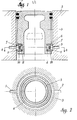
- numbers 1 and 2 clearly show the inlet and outlet holes of the oil under pressure, provided through the walls of the cylinder 3.
- the lubricating oil is made to circulate by means of a common lubrication pump (not shown).
- Numer 4 points out a groove which is suitably sized and is obtained on the skirt of the piston 5. It is important to observe that said groove 4 has no hole communicating with the inside of the piston 5.
- the scraper ring 6 is housed within said groove 4, said ring, as shown clearly, being opportunely shaped and having well determined features.
- Said scraper ring 6 is kept in its position by means of a dowel (not shown) so that it cannot rotate with respect to the piston.
- the holes 10 are obtained on said stub-groove of the scraper ring 6, said holes making the volume 9 to communicate with the volume defined by the groove 4 and by the scraper ring 6, which is pointed out with number 11. In the realization stage, said holes 10 will be arranged so as not to correspond with the transfer and exhaust ports.
- the lubricating oil is introduced through the hole 1 by the action of the lubrication pump and it goes into the volume 9 and the volume 11, and then it flows out freely through the outlet hole 2.
- the lubricated part corresponds to the part run by the scraper ring 6, i.e., to the length of the stroke of the piston 5.
- said scraper ring 6 is arranged on the lower rim of the piston 5 so as to avoid the overlapping of the ring with the slits which are typically present in two-stroke engines. As the slack between the piston 5 and the cylinder 3 is kept at a minimum when constructing-the same, an optimal lubrication effect is obtained with minimum losses.
- the number and the sizes of the inlet holes 1 and the outlet holes 2, as well as of the holes 10 can also be changed at any actual occasion according to the engine construction needs.
Landscapes
- Engineering & Computer Science (AREA)
- General Engineering & Computer Science (AREA)
- Mechanical Engineering (AREA)
- Lubrication Of Internal Combustion Engines (AREA)
- Lubrication Details And Ventilation Of Internal Combustion Engines (AREA)
Applications Claiming Priority (2)
| Application Number | Priority Date | Filing Date | Title |
|---|---|---|---|
| IT4816585 | 1985-06-04 | ||
| IT48165/85A IT1182734B (it) | 1985-06-04 | 1985-06-04 | Sistema di lubrificazione a recupero per pistone di un motore a due tempi con carter-pompa di lavaggio |
Publications (3)
| Publication Number | Publication Date |
|---|---|
| EP0204669A2 true EP0204669A2 (fr) | 1986-12-10 |
| EP0204669A3 EP0204669A3 (en) | 1988-03-16 |
| EP0204669B1 EP0204669B1 (fr) | 1990-05-02 |
Family
ID=11264946
Family Applications (1)
| Application Number | Title | Priority Date | Filing Date |
|---|---|---|---|
| EP86830148A Expired EP0204669B1 (fr) | 1985-06-04 | 1986-05-29 | Système de graissage avec récupération de l'huile pour un moteur à piston à deux temps avec une pompe de balayage sous carter de l'arbre de manivelle |
Country Status (6)
| Country | Link |
|---|---|
| US (1) | US4672931A (fr) |
| EP (1) | EP0204669B1 (fr) |
| DE (2) | DE3670880D1 (fr) |
| ES (1) | ES8703982A1 (fr) |
| IT (1) | IT1182734B (fr) |
| RO (1) | RO94296A (fr) |
Cited By (5)
| Publication number | Priority date | Publication date | Assignee | Title |
|---|---|---|---|---|
| EP0625389A1 (fr) * | 1993-05-19 | 1994-11-23 | Maschinenfabrik Müller-Weingarten AG | Garniture de coulée pour machine de coulée sous pression |
| DE19755687A1 (de) * | 1997-12-16 | 1999-06-17 | Dolmar Gmbh | Zweitakt-Ottomotor mit Getrenntschmierung |
| WO2011027140A1 (fr) * | 2009-09-02 | 2011-03-10 | Dan Merritt | Moteur à combustion interne |
| GB2493571A (en) * | 2011-08-10 | 2013-02-13 | Manousos Pattakos | A two-stroke internal combustion engine which uses a four-stroke engine cylinder lubrication arrangement |
| EP2620607A1 (fr) * | 2012-01-30 | 2013-07-31 | Wärtsilä Schweiz AG | Ensemble piston-cylindre et procédé d'alimentation en lubrifiant l'ensemble piston-cylindre pour un moteur à combustion interne |
Families Citing this family (11)
| Publication number | Priority date | Publication date | Assignee | Title |
|---|---|---|---|---|
| US4877257A (en) * | 1987-08-19 | 1989-10-31 | Ide Russell D | Piston ring |
| US4850313A (en) * | 1988-02-16 | 1989-07-25 | Peter Gibbons | Cruciform engine |
| DE3917755C2 (de) * | 1988-05-31 | 1995-02-02 | Atsugi Motor Parts Co Ltd | Kolben für eine Brennkraftmaschine |
| US5002025A (en) * | 1990-06-18 | 1991-03-26 | Crouse William H | Lubricating oil permeable cylinder wall ring |
| US6067952A (en) * | 1998-12-10 | 2000-05-30 | Brunswick Corporation | Cylinder bore lubrication with residual oil |
| AU2993800A (en) * | 1999-03-11 | 2000-09-28 | Outboard Marine Corporation | Oil injection system |
| IT1306569B1 (it) * | 1999-06-02 | 2001-06-18 | Motor Union Italia S R L | Dispositivo per ottenere un motore a due tempi a carter-pompa separato dal sistema di trasformazione del moto rettilineo alternato in moto |
| US6058900A (en) * | 1999-07-20 | 2000-05-09 | Brunswick Corporation | Internal combustion engine with improved cylinder wall lubrication system |
| US20100024759A1 (en) * | 2008-07-31 | 2010-02-04 | Dobransky Gary E | Two-stroke engine |
| US7779627B1 (en) * | 2009-02-05 | 2010-08-24 | Ries James D | Variable-displacement piston-cylinder device |
| RU2716773C1 (ru) * | 2019-10-14 | 2020-03-16 | Владимир Кузьмич Дюпин | Цилиндропоршневая группа двигателя внутреннего сгорания |
Family Cites Families (10)
| Publication number | Priority date | Publication date | Assignee | Title |
|---|---|---|---|---|
| DE550963C (de) * | 1932-05-23 | Stihl Andreas | Kolben fuer Zweitaktbrennkraftmaschinen | |
| DE657287C (de) * | 1935-02-23 | 1938-02-28 | Siemens App | Einrichtung zur Erzielung einer Durchlaufschmierung fuer Kolbenkraftmaschinen |
| DE1105661B (de) * | 1958-04-03 | 1961-04-27 | Kloeckner Humboldt Deutz Ag | Brennkraftkolbenmaschine mit Hubtaktschmierung der Zylinderlaufbahn |
| US3105695A (en) * | 1961-03-13 | 1963-10-01 | Sealed Power Corp | Piston ring assembly |
| DE2008140C3 (de) * | 1970-02-21 | 1975-03-20 | Maschinenfabrik Augsburg-Nuernberg Ag, 8500 Nuernberg | Kolben, insbesondere für Dieselbrennkraftmaschinen |
| US4242948A (en) * | 1977-12-16 | 1981-01-06 | Cummins Engine Company, Inc. | Insulated composite piston |
| US4245611A (en) * | 1978-09-05 | 1981-01-20 | General Motors Corporation | Ceramic insulated engine pistons |
| US4331065A (en) * | 1979-10-18 | 1982-05-25 | General Motors Corporation | Engine piston assembly with improved oil control |
| GB2113800B (en) * | 1982-01-19 | 1986-01-22 | Bernard Hooper | Lubricating 2-stroke engine pistons |
| US4432313A (en) * | 1982-05-27 | 1984-02-21 | Trw Inc. | Aluminum base material with hard facing deposit |
-
1985
- 1985-06-04 IT IT48165/85A patent/IT1182734B/it active
-
1986
- 1986-05-29 DE DE8686830148T patent/DE3670880D1/de not_active Expired - Fee Related
- 1986-05-29 DE DE198686830148T patent/DE204669T1/de active Pending
- 1986-05-29 EP EP86830148A patent/EP0204669B1/fr not_active Expired
- 1986-06-02 US US06/870,096 patent/US4672931A/en not_active Expired - Lifetime
- 1986-06-04 ES ES555711A patent/ES8703982A1/es not_active Expired
- 1986-06-04 RO RO86123602A patent/RO94296A/fr unknown
Cited By (7)
| Publication number | Priority date | Publication date | Assignee | Title |
|---|---|---|---|---|
| EP0625389A1 (fr) * | 1993-05-19 | 1994-11-23 | Maschinenfabrik Müller-Weingarten AG | Garniture de coulée pour machine de coulée sous pression |
| US5472039A (en) * | 1993-05-19 | 1995-12-05 | Maschinenfabrik Muller-Weingarten Ag | Casting set for a diecasting machine |
| DE19755687A1 (de) * | 1997-12-16 | 1999-06-17 | Dolmar Gmbh | Zweitakt-Ottomotor mit Getrenntschmierung |
| WO2011027140A1 (fr) * | 2009-09-02 | 2011-03-10 | Dan Merritt | Moteur à combustion interne |
| GB2493571A (en) * | 2011-08-10 | 2013-02-13 | Manousos Pattakos | A two-stroke internal combustion engine which uses a four-stroke engine cylinder lubrication arrangement |
| GB2493571B (en) * | 2011-08-10 | 2013-09-04 | Manousos Pattakos | Uniflow port-less two-stroke engine |
| EP2620607A1 (fr) * | 2012-01-30 | 2013-07-31 | Wärtsilä Schweiz AG | Ensemble piston-cylindre et procédé d'alimentation en lubrifiant l'ensemble piston-cylindre pour un moteur à combustion interne |
Also Published As
| Publication number | Publication date |
|---|---|
| IT8548165A0 (it) | 1985-06-04 |
| DE3670880D1 (de) | 1990-06-07 |
| EP0204669B1 (fr) | 1990-05-02 |
| ES555711A0 (es) | 1987-03-01 |
| US4672931A (en) | 1987-06-16 |
| IT1182734B (it) | 1987-10-05 |
| RO94296A (fr) | 1988-04-30 |
| ES8703982A1 (es) | 1987-03-01 |
| DE204669T1 (de) | 1987-09-24 |
| EP0204669A3 (en) | 1988-03-16 |
Similar Documents
| Publication | Publication Date | Title |
|---|---|---|
| EP0204669B1 (fr) | Système de graissage avec récupération de l'huile pour un moteur à piston à deux temps avec une pompe de balayage sous carter de l'arbre de manivelle | |
| US4056044A (en) | Oil cooled piston | |
| US4331108A (en) | Radial engine | |
| EP0003439B1 (fr) | Moteur à combustion interne | |
| US6216660B1 (en) | Lubricating system in a 4-cycle engine | |
| AU717428B2 (en) | Overhead cam engine | |
| US4332229A (en) | Double intake, supercharging I.C. engine | |
| US5479894A (en) | Two-stroke internal combustion engine | |
| CN214787751U (zh) | 一种低排放的摩托车及其发动机 | |
| US3948241A (en) | Lubricating and sealing system for internal combustion engines | |
| US6257192B1 (en) | Four cycle engine lubrication structure | |
| US5513608A (en) | Two cycle engine lubricating system | |
| EP0647804A1 (fr) | Moteur à combustion interne | |
| US6666183B2 (en) | V-type internal combustion engine | |
| GB2168429A (en) | I.c. engine blow-by gas passage and oil separating system | |
| US1382485A (en) | Internal-combustion engine | |
| US3487818A (en) | Short stroke two-cycle engine | |
| KR910004382B1 (ko) | 엔진 냉각장치 | |
| US4433655A (en) | Internal combustion engine | |
| US3888228A (en) | Engine oil tank | |
| US4331065A (en) | Engine piston assembly with improved oil control | |
| US6012421A (en) | Internal combustion engine with improved lubrication system | |
| SU1304753A3 (ru) | Поршневой двигатель внутреннего сгорани | |
| US6058900A (en) | Internal combustion engine with improved cylinder wall lubrication system | |
| CA2080132A1 (fr) | Moteur ou machine a combustion interne quadratique a pistons oscillants a double effet de forme rectangulaire et arquee |
Legal Events
| Date | Code | Title | Description |
|---|---|---|---|
| PUAI | Public reference made under article 153(3) epc to a published international application that has entered the european phase |
Free format text: ORIGINAL CODE: 0009012 |
|
| AK | Designated contracting states |
Kind code of ref document: A2 Designated state(s): DE FR GB |
|
| EL | Fr: translation of claims filed | ||
| DET | De: translation of patent claims | ||
| PUAL | Search report despatched |
Free format text: ORIGINAL CODE: 0009013 |
|
| AK | Designated contracting states |
Kind code of ref document: A3 Designated state(s): DE FR GB |
|
| 17P | Request for examination filed |
Effective date: 19880628 |
|
| 17Q | First examination report despatched |
Effective date: 19890220 |
|
| GRAA | (expected) grant |
Free format text: ORIGINAL CODE: 0009210 |
|
| AK | Designated contracting states |
Kind code of ref document: B1 Designated state(s): DE FR GB |
|
| REF | Corresponds to: |
Ref document number: 3670880 Country of ref document: DE Date of ref document: 19900607 |
|
| ET | Fr: translation filed | ||
| PLBE | No opposition filed within time limit |
Free format text: ORIGINAL CODE: 0009261 |
|
| STAA | Information on the status of an ep patent application or granted ep patent |
Free format text: STATUS: NO OPPOSITION FILED WITHIN TIME LIMIT |
|
| 26N | No opposition filed | ||
| REG | Reference to a national code |
Ref country code: FR Ref legal event code: TP Ref country code: FR Ref legal event code: CD |
|
| REG | Reference to a national code |
Ref country code: GB Ref legal event code: 732E |
|
| REG | Reference to a national code |
Ref country code: FR Ref legal event code: RM |
|
| PGFP | Annual fee paid to national office [announced via postgrant information from national office to epo] |
Ref country code: FR Payment date: 20010509 Year of fee payment: 16 |
|
| PGFP | Annual fee paid to national office [announced via postgrant information from national office to epo] |
Ref country code: GB Payment date: 20010523 Year of fee payment: 16 |
|
| PGFP | Annual fee paid to national office [announced via postgrant information from national office to epo] |
Ref country code: DE Payment date: 20010724 Year of fee payment: 16 |
|
| REG | Reference to a national code |
Ref country code: GB Ref legal event code: IF02 |
|
| PG25 | Lapsed in a contracting state [announced via postgrant information from national office to epo] |
Ref country code: GB Free format text: LAPSE BECAUSE OF NON-PAYMENT OF DUE FEES Effective date: 20020529 |
|
| PG25 | Lapsed in a contracting state [announced via postgrant information from national office to epo] |
Ref country code: DE Free format text: LAPSE BECAUSE OF NON-PAYMENT OF DUE FEES Effective date: 20021203 |
|
| GBPC | Gb: european patent ceased through non-payment of renewal fee |
Effective date: 20020529 |
|
| PG25 | Lapsed in a contracting state [announced via postgrant information from national office to epo] |
Ref country code: FR Free format text: LAPSE BECAUSE OF NON-PAYMENT OF DUE FEES Effective date: 20030131 |
|
| REG | Reference to a national code |
Ref country code: FR Ref legal event code: ST |