EP0204688A2 - Installation d'aérage pour liquides - Google Patents
Installation d'aérage pour liquides Download PDFInfo
- Publication number
- EP0204688A2 EP0204688A2 EP86890128A EP86890128A EP0204688A2 EP 0204688 A2 EP0204688 A2 EP 0204688A2 EP 86890128 A EP86890128 A EP 86890128A EP 86890128 A EP86890128 A EP 86890128A EP 0204688 A2 EP0204688 A2 EP 0204688A2
- Authority
- EP
- European Patent Office
- Prior art keywords
- stator
- flow channels
- rotor
- liquid
- boundary surfaces
- Prior art date
- Legal status (The legal status is an assumption and is not a legal conclusion. Google has not performed a legal analysis and makes no representation as to the accuracy of the status listed.)
- Granted
Links
Images
Classifications
-
- B—PERFORMING OPERATIONS; TRANSPORTING
- B01—PHYSICAL OR CHEMICAL PROCESSES OR APPARATUS IN GENERAL
- B01F—MIXING, e.g. DISSOLVING, EMULSIFYING OR DISPERSING
- B01F23/00—Mixing according to the phases to be mixed, e.g. dispersing or emulsifying
- B01F23/20—Mixing gases with liquids
- B01F23/23—Mixing gases with liquids by introducing gases into liquid media, e.g. for producing aerated liquids
- B01F23/233—Mixing gases with liquids by introducing gases into liquid media, e.g. for producing aerated liquids using driven stirrers with completely immersed stirring elements
- B01F23/2334—Mixing gases with liquids by introducing gases into liquid media, e.g. for producing aerated liquids using driven stirrers with completely immersed stirring elements provided with stationary guiding means surrounding at least partially the stirrer
- B01F23/23342—Mixing gases with liquids by introducing gases into liquid media, e.g. for producing aerated liquids using driven stirrers with completely immersed stirring elements provided with stationary guiding means surrounding at least partially the stirrer the stirrer being of the centrifugal type, e.g. with a surrounding stator
Definitions
- the invention relates to a ventilation device for liquids, consisting of an air and liquid-conveying rotor with a vertical axis of rotation and a stator surrounding the rotor, which has a closed ring of flow channels with a rectangular cross section for the liquid-air mixture, the vertical boundary surfaces of which are opposite each other an axial plane passing through the respective boundary surface in the region of the inner circumference of the stator are inclined in the direction of rotation of the rotor.
- the ventilation air drawn in axially via a central air line with the liquid also drawn in axially by the rotor is conveyed radially outward with intimate mixing into the stator, which consists of two ring disks arranged at an axial distance from one another and out vertical guide walls inserted between these ring washers.
- the flow channels which are delimited by the vertical guide walls and are rectangular in cross section, cause the liquid-air mixture to flow out into the liquid to be aerated, so that uniform ventilation of the liquid can be achieved in a certain area around the stator.
- the ventilation becomes weaker because the flow velocity of the liquid-air mixture decreases. This means that the diameter of the container receiving the liquid to be aerated must not exceed a certain dimension in order to ensure a uniform ventilation of the liquid over the entire container cross-section at a given rotor output.
- the invention is therefore based on the object of improving a ventilation device of the type described at the outset with simple means such that, with a given rotor output, uniform ventilation can also be achieved over a larger container cross section.
- the invention achieves the stated object in that the adjacent vertical boundary surfaces of flow channels arranged directly next to one another diverge against the outer circumference of the stator, the vertical boundary surfaces of each flow channel running parallel to one another at most with a deviation of 7 °.
- the vertical boundary surfaces of the individual flow channels run at least essentially parallel to one another, the exit velocity of the liquid-air mixture from the flow channels can be increased considerably compared to conventional stators with simple guide walls without having to increase the rotor power.
- the higher exit velocity of the liquid-air mixture requires a correspondingly larger outlet width of the liquid-air mixture, so that even ventilation of larger container cross sections can be ensured.
- This results in particularly advantageous design conditions because the size and shape of the rotor determine the ejection volume of air and liquid and thus the desired ventilation rate, while the formation of the flow channels of the stator is responsible for the range of the liquid-air mixture ejected.
- the exit velocity of the liquid-air mixture ejected from the stator can be influenced by the shape of the flow channels. If the vertical boundary surfaces of the individual flow channels diverge towards the outer circumference of the stator, the exit velocity of the liquid-air mixture is correspondingly reduced compared to the entry velocity into the stator. If the exit velocity is to be increased, the flow cross section of the flow channels towards the exit end must be reduced by the vertical boundary surfaces converging towards the outer circumference of the stator. However, the angle between the vertical boundary surfaces of the individual flow channels must not exceed 7 °, unless increased eddy formation is to be accepted. In this context, it must be borne in mind that turbulent flows considerably limit the possible range of the liquid-air mixture expelled.
- the flow channels can be designed differently.
- the arranged washers are provided.
- a particularly advantageous construction results, however, if the flow channels consist of U-profiles placed on an annular disc. This design not only offers advantageous manufacturing conditions with a comparatively low cost of materials, but also allows simple stator cleaning because the gusset areas between the individual U-profiles forming the flow channels are freely accessible.
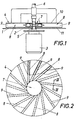
- the ventilation device shown which is arranged directly above a container base 1, essentially consists of a rotor 2, which is driven by a motor 3, and a stator 4 surrounding the rotor 2.
- the vertical rotor shaft 5 passes through the Container bottom 1, on which the motor 3 is flanged.
- the air to be introduced into the liquid of the container is sucked in via an air line 6 and fed axially to the rotor 2, which at the same time draws liquid from the container via an annular opening 7 of the stator 4 and conveys it with the air into the stator, as indicated by the flow arrows is.
- the liquid-air mixture is received in flow channels 8 which, according to FIGS. 1 to 3, are formed by vertical webs 9 which are inserted between two annular disks 10 and 11.
- the arrangement is such that adjacent webs 9 of flow channels 8 arranged directly next to one another diverge towards the outer circumference of the stator 4, so that the vertical boundary surfaces of the flow channels 8 run parallel to one another.
- This configuration results in an exit velocity of the flow from the flow channels 8 which corresponds approximately to the entry velocity of the liquid-air mixture conveyed by the rotor 2 into the stator 4, so that the flow continues over a large radius into the container due to the comparatively high exit velocity.
- This ensures even ventilation of containers of larger diameters if a corresponding number of flow channels ensures that the flows of adjacent flow channels do not diverge too much, especially against the region of the peripheral wall of the container.
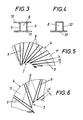
- a particularly simple stator construction can be obtained in that the flow channels 8 are formed by U-profiles 12 which are placed on an annular disk 13.
- This design not only ensures simple manufacture, but also offers advantages in terms of stator cleaning because the gusset areas between adjacent flow channels are freely accessible.
- the vertical boundary surfaces of the individual flow channels 8 can deviate from their parallel course. If, for example, the webs 9 of the individual flow channels 8 are arranged diverging towards the outer circumference of the stator 4, the flow within the flow channels 8 is slowed down. The angle ⁇ between the vertical webs 9 must not exceed 7 °, since otherwise with An increased eddy formation is to be expected, which greatly limits the range of the flow emerging from the flow channels 8.
- the webs 9 can converge towards the outside, as is indicated in FIG. 6.
- the angle a between the vertical webs 9 of the individual flow channels must be limited to a maximum of 7 °.
- stator With the help of the aeration device shown, the special design of the stator enables liquid to be evenly ventilated over larger base areas, these aeration devices being particularly suitable for use in submerged vinegar fermentation, in yeast production or in wastewater treatment.
- the invention is of course not limited to the illustrated embodiment of a ventilation device.
- very differently constructed rotors can be used. B. is possible to suck liquid not only according to FIG. 1 on one side, but on both sides of the rotor.
- the rotor construction can also be carried out in such a way that the air can be drawn in from below the rotor and that the motor is mounted in the container above the rotor in the form of a submersible motor of known design. Of course, any gas other than air can be drawn in and distributed in any given liquid.
- the inclination of the flow channels 8 with respect to the radial direction is then to be determined, the number of flow channels being selected depending on the inclination of the flow channels and the container diameter.
- adjacent webs 9 of flow channels 8 arranged directly next to one another can be formed by a common intermediate body which has a wedge-shaped shape in plan, so that in turn the vertical boundary surfaces of each flow comb run at least substantially parallel.
Landscapes
- Chemical & Material Sciences (AREA)
- Chemical Kinetics & Catalysis (AREA)
- Aeration Devices For Treatment Of Activated Polluted Sludge (AREA)
- Mixers Of The Rotary Stirring Type (AREA)
- Structures Of Non-Positive Displacement Pumps (AREA)
- Apparatus Associated With Microorganisms And Enzymes (AREA)
- Physical Or Chemical Processes And Apparatus (AREA)
- Biological Treatment Of Waste Water (AREA)
Applications Claiming Priority (2)
| Application Number | Priority Date | Filing Date | Title |
|---|---|---|---|
| AT1696/85 | 1985-06-05 | ||
| AT0169685A AT383108B (de) | 1985-06-05 | 1985-06-05 | Belueftungsvorrichtung fuer fluessigkeiten |
Publications (4)
| Publication Number | Publication Date |
|---|---|
| EP0204688A2 true EP0204688A2 (fr) | 1986-12-10 |
| EP0204688A3 EP0204688A3 (en) | 1988-06-22 |
| EP0204688B1 EP0204688B1 (fr) | 1990-01-03 |
| EP0204688B2 EP0204688B2 (fr) | 1992-11-11 |
Family
ID=3519010
Family Applications (1)
| Application Number | Title | Priority Date | Filing Date |
|---|---|---|---|
| EP86890128A Expired - Lifetime EP0204688B2 (fr) | 1985-06-05 | 1986-05-07 | Installation d'aérage pour liquides |
Country Status (10)
| Country | Link |
|---|---|
| EP (1) | EP0204688B2 (fr) |
| JP (1) | JPS6244167A (fr) |
| CN (1) | CN86103733A (fr) |
| AT (1) | AT383108B (fr) |
| BR (1) | BR8602601A (fr) |
| DE (1) | DE3616680A1 (fr) |
| ES (1) | ES8703748A1 (fr) |
| FI (1) | FI88262C (fr) |
| IN (1) | IN165315B (fr) |
| SU (1) | SU1625330A3 (fr) |
Cited By (4)
| Publication number | Priority date | Publication date | Assignee | Title |
|---|---|---|---|---|
| DE4207077A1 (de) * | 1991-03-07 | 1992-09-10 | Horst Adler | Kompaktklaeranlage |
| DE9316251U1 (de) * | 1993-10-25 | 1994-02-10 | Charatjan, Manuela, 76332 Bad Herrenalb | Vorrichtung zum Rühren, bzw. zum Rühren und gleichzeitigen Begasen von Flüssigkeiten, Suspensionen und heterogenen Fluiden |
| US5356570A (en) * | 1992-09-10 | 1994-10-18 | Heinrich Frings Gmbh & Co Kg | Apparatus for aerating liquids |
| US5358671A (en) * | 1992-07-17 | 1994-10-25 | Outokumpu Mintec Oy | Aerator device |
Families Citing this family (8)
| Publication number | Priority date | Publication date | Assignee | Title |
|---|---|---|---|---|
| JPH0717440Y2 (ja) * | 1988-05-18 | 1995-04-26 | 株式会社荏原製作所 | 攪拌・曝気装置 |
| DE19519553C2 (de) * | 1995-05-27 | 1997-04-24 | Michael Dipl Ing Godzik | Kreiselbelüfter zum Einbringen eines Gases in eine Flüssigkeit |
| DE102009044168A1 (de) | 2009-10-02 | 2011-04-07 | Green Finance Ag | Verfahren und Vorrichtung zur kontinuierlichen Herstellung von Alkylestern höherer Fettsäuren |
| CN102921320A (zh) * | 2012-11-05 | 2013-02-13 | 无锡托普搅拌设备有限公司 | 一种气液分散搅拌器 |
| BR112018006973B1 (pt) * | 2015-10-19 | 2021-11-23 | Société des Produits Nestlé S.A. | Aparelho e método para aeração de um produto alimentício |
| WO2020213048A1 (fr) * | 2019-04-15 | 2020-10-22 | エム・テクニック株式会社 | Agitateur |
| US11241661B2 (en) | 2019-04-15 | 2022-02-08 | M. Technique Co., Ltd. | Stirrer |
| CN117378890A (zh) * | 2023-10-11 | 2024-01-12 | 湖南叁陆伍科技有限公司 | 一种气动床垫生产加工设备及气动床垫结构 |
Family Cites Families (6)
| Publication number | Priority date | Publication date | Assignee | Title |
|---|---|---|---|---|
| AT269083B (de) * | 1966-04-05 | 1969-03-10 | Frings Fa Heinrich | Belüftungsvorrichtung für Flüssigkeiten |
| US3690621A (en) * | 1969-03-04 | 1972-09-12 | Itsuko Tanaka | Agitator |
| NO142830C (no) * | 1978-02-28 | 1980-10-29 | Trondhjems Mek Verksted As | Anordning for fordeling av en gass i et vaeskemedium |
| FR2444494A1 (fr) * | 1978-12-21 | 1980-07-18 | Jeumont Schneider | Dispositif permettant de dissoudre et/ou de melanger un fluide dans un liquide, et pouvant etre notamment utilise pour l'aeration des eaux residuaires |
| DE2907257C2 (de) * | 1979-02-24 | 1982-04-22 | Ukrainskij Naucno-Issledovatel'skij Uglechimiceskij Institut, Charkov | Vorrichtung zur Durchlüftung von Trüben |
| JPS5823036U (ja) | 1981-07-31 | 1983-02-14 | パイオニア株式会社 | テ−プレコ−ダ |
-
1985
- 1985-06-05 AT AT0169685A patent/AT383108B/de not_active IP Right Cessation
-
1986
- 1986-05-07 EP EP86890128A patent/EP0204688B2/fr not_active Expired - Lifetime
- 1986-05-16 DE DE19863616680 patent/DE3616680A1/de active Granted
- 1986-05-19 IN IN378/CAL/86A patent/IN165315B/en unknown
- 1986-05-21 FI FI862145A patent/FI88262C/fi not_active IP Right Cessation
- 1986-05-30 CN CN198686103733A patent/CN86103733A/zh active Pending
- 1986-06-04 SU SU864027574A patent/SU1625330A3/ru active
- 1986-06-04 JP JP61128299A patent/JPS6244167A/ja active Granted
- 1986-06-04 BR BR8602601A patent/BR8602601A/pt not_active IP Right Cessation
- 1986-06-05 ES ES555750A patent/ES8703748A1/es not_active Expired
Cited By (4)
| Publication number | Priority date | Publication date | Assignee | Title |
|---|---|---|---|---|
| DE4207077A1 (de) * | 1991-03-07 | 1992-09-10 | Horst Adler | Kompaktklaeranlage |
| US5358671A (en) * | 1992-07-17 | 1994-10-25 | Outokumpu Mintec Oy | Aerator device |
| US5356570A (en) * | 1992-09-10 | 1994-10-18 | Heinrich Frings Gmbh & Co Kg | Apparatus for aerating liquids |
| DE9316251U1 (de) * | 1993-10-25 | 1994-02-10 | Charatjan, Manuela, 76332 Bad Herrenalb | Vorrichtung zum Rühren, bzw. zum Rühren und gleichzeitigen Begasen von Flüssigkeiten, Suspensionen und heterogenen Fluiden |
Also Published As
| Publication number | Publication date |
|---|---|
| FI862145A0 (fi) | 1986-05-21 |
| EP0204688B2 (fr) | 1992-11-11 |
| BR8602601A (pt) | 1987-02-03 |
| CN86103733A (zh) | 1986-12-17 |
| ATA169685A (de) | 1986-10-15 |
| JPS6244167A (ja) | 1987-02-26 |
| DE3616680C2 (fr) | 1989-05-24 |
| EP0204688B1 (fr) | 1990-01-03 |
| EP0204688A3 (en) | 1988-06-22 |
| FI862145L (fi) | 1986-12-06 |
| ES555750A0 (es) | 1987-03-01 |
| DE3616680A1 (de) | 1986-12-11 |
| SU1625330A3 (ru) | 1991-01-30 |
| FI88262C (fi) | 1993-04-26 |
| ES8703748A1 (es) | 1987-03-01 |
| IN165315B (fr) | 1989-09-16 |
| FI88262B (fi) | 1993-01-15 |
| JPH0313866B2 (fr) | 1991-02-25 |
| AT383108B (de) | 1987-05-25 |
Similar Documents
| Publication | Publication Date | Title |
|---|---|---|
| DE2216767C3 (de) | Vorrichtung zur biologischen Reinigung von Abwasser | |
| EP0204688A2 (fr) | Installation d'aérage pour liquides | |
| DE1557138A1 (de) | Vorrichtung zum Begasen von Fluessigkeiten | |
| DE102019101934A1 (de) | Rührorganvorrichtung | |
| DE1265137B (de) | Ruehrwerk zum Belueften von Fluessigkeiten | |
| DE3782951T2 (de) | Ruehrer. | |
| DE3001829C2 (fr) | ||
| DE2924458C2 (de) | Extraktionsvorrichtung für die Flüssig-Flüssig-Extraktion | |
| DE29818255U1 (de) | Selbstansaugende, rotierende Dispergiervorrichtung | |
| DE2559170C2 (de) | Oberflächenbelüftungskreisel | |
| DE2157444C3 (de) | Dynamische Trennvorrichtung zum Abtrennen von in verunreinigten Flüssigkeiten suspendierten Teilchen | |
| DE8234623U1 (de) | Ruehrvorrichtung | |
| DE828100C (de) | In beiden Achsrichtungen saugender Mischkreisel | |
| DE3616680C3 (fr) | ||
| DE2907257C2 (de) | Vorrichtung zur Durchlüftung von Trüben | |
| DE2115083A1 (de) | Vorrichtung zur innigen Kontaktierung von fluiden Medien unterschiedlicher Dichte | |
| EP0216871B1 (fr) | Agencement d'elimination continue de vapeur ou de gaz contenus dans des liquides tendant a former des mousses | |
| DE2646517C2 (de) | Begasungsvorrichtung | |
| DE2164359C3 (de) | Oberflächenbelüftungskreisel zur Eintragung von Luft oder einem anderen Sauerstoffgasgemisch in Abwässer oder ähnliche Flüssigkeiten | |
| DE2559235B2 (de) | Begasungsvorrichtung | |
| DE3245641A1 (de) | Ruehrvorrichtung | |
| DE29819704U1 (de) | Begasungsvorrichtung für Flüssigkeiten | |
| DE2241654B2 (de) | Lufteinlaß für Gebläse | |
| DE1557223B2 (de) | Vorrichtung zum Dispergieren von Gasen und/oder Fluessigkeiten und/oder Feststoffen in Fluessigkeiten | |
| DE3705716C2 (de) | Vorrichtung zum Fördern und Begasen eines Flüssigkeitsgasgemisches |
Legal Events
| Date | Code | Title | Description |
|---|---|---|---|
| PUAI | Public reference made under article 153(3) epc to a published international application that has entered the european phase |
Free format text: ORIGINAL CODE: 0009012 |
|
| AK | Designated contracting states |
Kind code of ref document: A2 Designated state(s): CH FR GB IT LI SE |
|
| PUAL | Search report despatched |
Free format text: ORIGINAL CODE: 0009013 |
|
| AK | Designated contracting states |
Kind code of ref document: A3 Designated state(s): CH FR GB IT LI SE |
|
| 17P | Request for examination filed |
Effective date: 19881213 |
|
| EL | Fr: translation of claims filed | ||
| 17Q | First examination report despatched |
Effective date: 19890608 |
|
| EM | Fr: revised translation of claims filed | ||
| GRAA | (expected) grant |
Free format text: ORIGINAL CODE: 0009210 |
|
| AK | Designated contracting states |
Kind code of ref document: B1 Designated state(s): CH FR GB IT LI SE |
|
| ITF | It: translation for a ep patent filed | ||
| GBT | Gb: translation of ep patent filed (gb section 77(6)(a)/1977) | ||
| ET | Fr: translation filed | ||
| PLBI | Opposition filed |
Free format text: ORIGINAL CODE: 0009260 |
|
| 26 | Opposition filed |
Opponent name: OUTOKUMPU OY Effective date: 19901003 |
|
| PUAH | Patent maintained in amended form |
Free format text: ORIGINAL CODE: 0009272 |
|
| STAA | Information on the status of an ep patent application or granted ep patent |
Free format text: STATUS: PATENT MAINTAINED AS AMENDED |
|
| 27A | Patent maintained in amended form |
Effective date: 19921111 |
|
| AK | Designated contracting states |
Kind code of ref document: B2 Designated state(s): CH FR GB IT LI SE |
|
| ITF | It: translation for a ep patent filed | ||
| GBTA | Gb: translation of amended ep patent filed (gb section 77(6)(b)/1977) |
Effective date: 19921216 |
|
| ET3 | Fr: translation filed ** decision concerning opposition | ||
| ITTA | It: last paid annual fee | ||
| EAL | Se: european patent in force in sweden |
Ref document number: 86890128.1 |
|
| PGFP | Annual fee paid to national office [announced via postgrant information from national office to epo] |
Ref country code: SE Payment date: 19960429 Year of fee payment: 11 |
|
| PG25 | Lapsed in a contracting state [announced via postgrant information from national office to epo] |
Ref country code: SE Effective date: 19970508 |
|
| EUG | Se: european patent has lapsed |
Ref document number: 86890128.1 |
|
| PGFP | Annual fee paid to national office [announced via postgrant information from national office to epo] |
Ref country code: FR Payment date: 20010411 Year of fee payment: 16 |
|
| PGFP | Annual fee paid to national office [announced via postgrant information from national office to epo] |
Ref country code: GB Payment date: 20010423 Year of fee payment: 16 |
|
| PGFP | Annual fee paid to national office [announced via postgrant information from national office to epo] |
Ref country code: CH Payment date: 20010528 Year of fee payment: 16 |
|
| REG | Reference to a national code |
Ref country code: GB Ref legal event code: IF02 |
|
| PG25 | Lapsed in a contracting state [announced via postgrant information from national office to epo] |
Ref country code: GB Free format text: LAPSE BECAUSE OF NON-PAYMENT OF DUE FEES Effective date: 20020507 |
|
| PG25 | Lapsed in a contracting state [announced via postgrant information from national office to epo] |
Ref country code: LI Free format text: LAPSE BECAUSE OF NON-PAYMENT OF DUE FEES Effective date: 20020531 Ref country code: CH Free format text: LAPSE BECAUSE OF NON-PAYMENT OF DUE FEES Effective date: 20020531 |
|
| GBPC | Gb: european patent ceased through non-payment of renewal fee |
Effective date: 20020507 |
|
| REG | Reference to a national code |
Ref country code: CH Ref legal event code: PL |
|
| PG25 | Lapsed in a contracting state [announced via postgrant information from national office to epo] |
Ref country code: FR Free format text: LAPSE BECAUSE OF NON-PAYMENT OF DUE FEES Effective date: 20030131 |
|
| REG | Reference to a national code |
Ref country code: FR Ref legal event code: ST |
|
| PG25 | Lapsed in a contracting state [announced via postgrant information from national office to epo] |
Ref country code: IT Free format text: LAPSE BECAUSE OF NON-PAYMENT OF DUE FEES;WARNING: LAPSES OF ITALIAN PATENTS WITH EFFECTIVE DATE BEFORE 2007 MAY HAVE OCCURRED AT ANY TIME BEFORE 2007. THE CORRECT EFFECTIVE DATE MAY BE DIFFERENT FROM THE ONE RECORDED. Effective date: 20050507 |