EP0204835B1 - Palier de plateau oscillant de machine hydraulique avec un systeme pour retenir des roulements unitaires - Google Patents
Palier de plateau oscillant de machine hydraulique avec un systeme pour retenir des roulements unitaires Download PDFInfo
- Publication number
- EP0204835B1 EP0204835B1 EP86900486A EP86900486A EP0204835B1 EP 0204835 B1 EP0204835 B1 EP 0204835B1 EP 86900486 A EP86900486 A EP 86900486A EP 86900486 A EP86900486 A EP 86900486A EP 0204835 B1 EP0204835 B1 EP 0204835B1
- Authority
- EP
- European Patent Office
- Prior art keywords
- swashplate
- housing
- hydraulic unit
- bearing
- unit according
- Prior art date
- Legal status (The legal status is an assumption and is not a legal conclusion. Google has not performed a legal analysis and makes no representation as to the accuracy of the status listed.)
- Expired
Links
- 238000006073 displacement reaction Methods 0.000 claims description 20
- 239000000463 material Substances 0.000 claims description 5
- 238000005096 rolling process Methods 0.000 claims description 4
- 239000004677 Nylon Substances 0.000 claims description 2
- 229920001778 nylon Polymers 0.000 claims description 2
- 230000000712 assembly Effects 0.000 description 8
- 238000000429 assembly Methods 0.000 description 8
- 239000004033 plastic Substances 0.000 description 5
- 229920003023 plastic Polymers 0.000 description 5
- 238000010276 construction Methods 0.000 description 2
- 229910000760 Hardened steel Inorganic materials 0.000 description 1
- 229910000831 Steel Inorganic materials 0.000 description 1
- 230000002411 adverse Effects 0.000 description 1
- 238000003491 array Methods 0.000 description 1
- 230000009977 dual effect Effects 0.000 description 1
- 238000004519 manufacturing process Methods 0.000 description 1
- 239000010959 steel Substances 0.000 description 1
Images

Classifications
-
- F—MECHANICAL ENGINEERING; LIGHTING; HEATING; WEAPONS; BLASTING
- F16—ENGINEERING ELEMENTS AND UNITS; GENERAL MEASURES FOR PRODUCING AND MAINTAINING EFFECTIVE FUNCTIONING OF MACHINES OR INSTALLATIONS; THERMAL INSULATION IN GENERAL
- F16C—SHAFTS; FLEXIBLE SHAFTS; ELEMENTS OR CRANKSHAFT MECHANISMS; ROTARY BODIES OTHER THAN GEARING ELEMENTS; BEARINGS
- F16C33/00—Parts of bearings; Special methods for making bearings or parts thereof
- F16C33/30—Parts of ball or roller bearings
- F16C33/46—Cages for rollers or needles
- F16C33/48—Cages for rollers or needles for multiple rows of rollers or needles
-
- F—MECHANICAL ENGINEERING; LIGHTING; HEATING; WEAPONS; BLASTING
- F01—MACHINES OR ENGINES IN GENERAL; ENGINE PLANTS IN GENERAL; STEAM ENGINES
- F01B—MACHINES OR ENGINES, IN GENERAL OR OF POSITIVE-DISPLACEMENT TYPE, e.g. STEAM ENGINES
- F01B13/00—Reciprocating-piston machines or engines with rotating cylinders in order to obtain the reciprocating-piston motion
- F01B13/04—Reciprocating-piston machines or engines with rotating cylinders in order to obtain the reciprocating-piston motion with more than one cylinder
-
- F—MECHANICAL ENGINEERING; LIGHTING; HEATING; WEAPONS; BLASTING
- F01—MACHINES OR ENGINES IN GENERAL; ENGINE PLANTS IN GENERAL; STEAM ENGINES
- F01B—MACHINES OR ENGINES, IN GENERAL OR OF POSITIVE-DISPLACEMENT TYPE, e.g. STEAM ENGINES
- F01B3/00—Reciprocating-piston machines or engines with cylinder axes coaxial with, or parallel or inclined to, main shaft axis
- F01B3/0032—Reciprocating-piston machines or engines with cylinder axes coaxial with, or parallel or inclined to, main shaft axis having rotary cylinder block
- F01B3/0076—Connection between cylinder barrel and inclined swash plate
-
- F—MECHANICAL ENGINEERING; LIGHTING; HEATING; WEAPONS; BLASTING
- F04—POSITIVE - DISPLACEMENT MACHINES FOR LIQUIDS; PUMPS FOR LIQUIDS OR ELASTIC FLUIDS
- F04B—POSITIVE-DISPLACEMENT MACHINES FOR LIQUIDS; PUMPS
- F04B1/00—Multi-cylinder machines or pumps characterised by number or arrangement of cylinders
- F04B1/12—Multi-cylinder machines or pumps characterised by number or arrangement of cylinders having cylinder axes coaxial with, or parallel or inclined to, main shaft axis
- F04B1/20—Multi-cylinder machines or pumps characterised by number or arrangement of cylinders having cylinder axes coaxial with, or parallel or inclined to, main shaft axis having rotary cylinder block
- F04B1/2014—Details or component parts
- F04B1/2078—Swash plates
- F04B1/2085—Bearings for swash plates or driving axles
-
- F—MECHANICAL ENGINEERING; LIGHTING; HEATING; WEAPONS; BLASTING
- F16—ENGINEERING ELEMENTS AND UNITS; GENERAL MEASURES FOR PRODUCING AND MAINTAINING EFFECTIVE FUNCTIONING OF MACHINES OR INSTALLATIONS; THERMAL INSULATION IN GENERAL
- F16C—SHAFTS; FLEXIBLE SHAFTS; ELEMENTS OR CRANKSHAFT MECHANISMS; ROTARY BODIES OTHER THAN GEARING ELEMENTS; BEARINGS
- F16C19/00—Bearings with rolling contact, for exclusively rotary movement
- F16C19/50—Other types of ball or roller bearings
- F16C19/502—Other types of ball or roller bearings with rolling elements in rows not forming a full circle
-
- F—MECHANICAL ENGINEERING; LIGHTING; HEATING; WEAPONS; BLASTING
- F16—ENGINEERING ELEMENTS AND UNITS; GENERAL MEASURES FOR PRODUCING AND MAINTAINING EFFECTIVE FUNCTIONING OF MACHINES OR INSTALLATIONS; THERMAL INSULATION IN GENERAL
- F16C—SHAFTS; FLEXIBLE SHAFTS; ELEMENTS OR CRANKSHAFT MECHANISMS; ROTARY BODIES OTHER THAN GEARING ELEMENTS; BEARINGS
- F16C33/00—Parts of bearings; Special methods for making bearings or parts thereof
- F16C33/30—Parts of ball or roller bearings
- F16C33/306—Means to synchronise movements
-
- F—MECHANICAL ENGINEERING; LIGHTING; HEATING; WEAPONS; BLASTING
- F16—ENGINEERING ELEMENTS AND UNITS; GENERAL MEASURES FOR PRODUCING AND MAINTAINING EFFECTIVE FUNCTIONING OF MACHINES OR INSTALLATIONS; THERMAL INSULATION IN GENERAL
- F16C—SHAFTS; FLEXIBLE SHAFTS; ELEMENTS OR CRANKSHAFT MECHANISMS; ROTARY BODIES OTHER THAN GEARING ELEMENTS; BEARINGS
- F16C2360/00—Engines or pumps
Definitions
- the invention relates to a unitary bearing cage used for-plural spaced apart roller bearings supporting a tiltable swashplate of a variable displacement hydraulic unit and which requires the use of only a single bearing cage locating means.
- Axial piston variable displacement hydraulic units utilize a tiltable swashplate to control the displacement of pistons within a rotating cylinder block.
- One common type of tiltable swashplate is a cradle type swashplate which is supported at one end of the housing by a pair of arcuate bearings having rolling elements. These roller bearings are spaced apart in a transverse plane to permit the passage of a shaft coupled to the cylinder block.
- Each of the pair of roller bearings is provided with a retainer locating the individual rollers of the bearing.
- Common roller bearing practice requires that the arcuate displacement of the roller bearing cage be one half of the arcuate displacement of the cradle swashplate in order to obtain an exclusively rolling motion of the roller elements.
- roller bearings are arcuate, but not totally circular, repeated tilting of the swashplate can lead to slipping of the roller elements between the housing and the cradle swashplate to positions other than the desired optimum support positions for resisting the axial thrust of the swashplate.
- US Patent (Schwede et al) 4029367 discloses a variable hydraulic unit comprising a housing ; a cylinder block mounted therein for rotation about an axis, the cylinder block having a plurality of axial cylinders therein each containing a reciprocating piston ; a swashplate for controlling the displacement of the pistons within the cylinders ; a rotatable shaft connected to the cylinder block and extending along the axis through an opening formed in the swashplate ; support means for tiltably supporting the swashplate in the housing ; and positioning means for controlling the tilt of the swashplate relative to the housing.
- the support means comprises a pair of spaced apart sets of roller bearings each in its own part arcuate bearing cage. There is no connection between the bearing cages on opposite sides of the shaft.
- each of these prior art solutions requires the use of a pair of spaced apart locating means for the respective roller bearing cages. This duplicates the expense of the locating means and, furthermore, unduly complicates the assembly of the unit.
- the invention provides a variable displacement hydraulic unit comprising a housing, a cylinder block mounted in the housing for rotation about an axis, the cylinder block having a plurality of axial cylinders therein each containing a reciprocating piston, a swashplate for controlling the displacement of the pistons within the cylinders, a rotatable shaft connected to the cylinder block and extending along the axis through an opening formed in the swashplaste, positioning means for controlling the tilt of the swashplate relative to the housing, and roller bearing support means for tiltably supporting the swashplate in the housing, comprising a pair of spaced apart sets of rollable bearing elements positioned between the swashplate and the housing one on each side of the shaft, and means constraining the bearing elements to a rolling motion in a generally arcuate path, characterised in that the constraining means comprises a unitary bearing cage assembly for retaining the bearing elements of both sets.
- the use of a single bearing cage reduces the bearing cost and simplifies the assembly. In particular, it permits the use of a single locating means on one side only of the rotatable shaft, rather than dual locating means as in the prior art. This not only reduces the assembly steps required but also halves the cost of the bearing cage locaters.
- a single locating means and housing side cover is provided.
- the single locating means controls the displacement of one of the sets of bearings by direct engagement with the bearing cage on that side of the rotatable shaft, and controls the displacement of the other of the sets of bearings through the unitary construction of the cage.
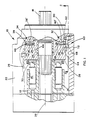
- the unitary bearing cage assembly is used in a variable displacement hydraulic unit 10 shown in FIG. 1.
- the hydraulic unit may be either a pump or a motor and has a rotatable cylinder block 12 with a plurality of cylinder bores 14 with reciprocating pistons 16 therein.
- the cylinder block is secured to a shaft 18 and rotates about a central axis 20.
- a cradle swashplate 24 Located at one end of a housing 22 is a cradle swashplate 24 which is adapted for tilting or pivotal movement induced by input mechanism represented by lever 26.
- the swashplate has a planar cam surface 28 engaged by piston slippers 30 so that the tilting movement of the swashplate 24 controls the axial displacement of the pistons 16.
- the cradle swashplate 24 is mounted on the housing 22 by a pair of roller bearing assemblies 32 and 34.
- Each of the roller bearing assemblies has a plurality of rollable elements such as rollers 36.
- Each of the roller bearing assemblies 32 and 34 may also be provided with an outer race such as 38 and 40 secured to arcuate portions 21' of the housing by pins 38' and 40'.
- an inner race is not utilized and the rollers 36 directly engage a pair of outwardly facing arcuate portions 42 and 43 of the swashplate 24.
- the cradle swashplate 24 is provided with a central opening 44 which permits passage of the shaft 18 through the centre of the swashplate. Furthermore, also to prevent interference with the shaft 18, the bearing assemblies 32 and 34 must be spaced apart by a distance greater than the width of the opening 44 so that each set of rollers can engage a substantial arcuate portion of the swashplate 24.
- the bearing assemblies 32 and 34 are provided with retainers 46 and 48 which act as individual roller cages for the respective bearings 32 and 34.
- Each of the retainers 46 and 48 is provided with a plurality of slots 50 which arcuately locate the individual rollers 36.
- the two arcuate retainers 46 and 48 are joined together to form a unitary cage assembly 52 as shown in FIG. 3.
- the unitary cage assembly 52 is formed of a single piece of material having cross members 54 and 56 join the individual retainers 46 and 48 adjacent the ends of the retainers.
- each of the retainer sections 46 and 48 have a pair of inwardly directed transverse legs 46' and 48' joined together by tongue and groove joints to form the cross members 54 and 56.
- Still another form contemplated is having each of the pair of retainers 46 and 48 joined by separately formed cross members 54 and 56 being secured to the pair of retainers 46 and 48 to form the unitary cage assembly 52.
- the spaced apart retainers 46 and 48, along with the transverse cross members 54 and 56 provide a large central opening 58 as seen in FIG. 3 which permits passage of the shaft 18 to the exterior of the housing 12.
- the bearing cage assembly 52 may be formed of many materials, it had been found particularly advantageous to form the cage 52 from a plastics material such as hard nylon. This permits limited radial deformation of the cage while still providing sufficient strength to assure the proper arcuate spacing between the slots 50 which locate the rollers 36, and also to maintain proper parallel spacing between retainers 46 and 48. Also a plastics cage reduces the friction between the cage and the hardened steel rollers.
- the unitary cage assembly 52 assures that the retainers are in parallel alignment both during assembly and operation of the hydraulic unit 10. Also, it has been determined that the manufacturing cost of the unitary cage, especially when formed by two pieces such as shown in FIG. 3 is no more expensive than forming a pair of individual retainers, and thus the advantage of assuring parallel alignment of the retainers 46 and 48 is obtained with little or no extra cost.
- the movement of the roller retainer or cage be one half the relative movement of the supported or supporting parts.
- the cage 52 be limited to arcuate movement that is one half the arcuate movement of the swashplate 24. This arcuate movement relationship is assured by a single locating means 60, such as taught in Figs. 1 and 2.
- the locating means 60 can take many forms as discussed in the background of the invention.
- One simple and inexpensive form found desirable consists of a pivot pin 62 secured to the housing 12, a pivot pin 64 secured to the swashplate 24, and a link 66 means interconnecting the pins 62 and 64.
- a loss motion means is provided such as by elongated slot 66' where the link engages pin 64 on the swashplate 24.
- One inexpensive means providing the link 66 is a bent wire form.
- Extending outwardly from the cage 52 is a tab 68 having a slot 70 which engages the central portion of the link 66.
- pin 62 and 64 causes a separate pivotal movement of link 66 which either aids or limits the arcuate movement of the cage 52 as the slot 70 slides on the link.
- the proper spacing between pins 62 and 64 relative to the tab 68 generally the distance between pin 62 and tab 68 being twice the distance between the pin 64 and the tab 68 when the swashplate 24 is centered, provides the desired two to one relationship between the arcuate movement of the swashplate 24 and the arcuate movement of the cage 52.
- a removable housing side cover 72 can be used to provide ready access to the locating means 60 to facilitate the link 66 being positioned over pin 64, into slot 70 and secured to the pin 62 fastened on the housing 12 after the rotating block and swashplate of the hydraulic unit has been assembled. Since there is only one locating means 60, there is no necessity for having other access to the interior cavity of the housing for assembly of the locating means.
- the present invention meets the objectives of providing an inexpensive and readily assembled roller bearing assembly supporting a pivotable or tiltable swashplate in a hydraulic unit. Furthermore, the present invention requires the use of only one locating means properly to position the roller retainers for a pair of parallel spaced apart roller bearing assemblies spanning a shaft passing between the roller bearing assemblies.
Landscapes
- Engineering & Computer Science (AREA)
- General Engineering & Computer Science (AREA)
- Mechanical Engineering (AREA)
- Reciprocating Pumps (AREA)
- Dairy Products (AREA)
- Beans For Foods Or Fodder (AREA)
Abstract
Claims (10)
Applications Claiming Priority (2)
| Application Number | Priority Date | Filing Date | Title |
|---|---|---|---|
| US680438 | 1984-12-11 | ||
| US06/680,438 US4627330A (en) | 1984-12-11 | 1984-12-11 | Unitary bearing retainer for a swashplate bearing |
Publications (3)
| Publication Number | Publication Date |
|---|---|
| EP0204835A1 EP0204835A1 (fr) | 1986-12-17 |
| EP0204835A4 EP0204835A4 (fr) | 1987-07-23 |
| EP0204835B1 true EP0204835B1 (fr) | 1989-04-26 |
Family
ID=24731113
Family Applications (1)
| Application Number | Title | Priority Date | Filing Date |
|---|---|---|---|
| EP86900486A Expired EP0204835B1 (fr) | 1984-12-11 | 1985-12-10 | Palier de plateau oscillant de machine hydraulique avec un systeme pour retenir des roulements unitaires |
Country Status (8)
| Country | Link |
|---|---|
| US (1) | US4627330A (fr) |
| EP (1) | EP0204835B1 (fr) |
| JP (1) | JPS62501019A (fr) |
| BR (1) | BR8507106A (fr) |
| CA (1) | CA1245132A (fr) |
| DE (1) | DE3569779D1 (fr) |
| SU (1) | SU1501927A3 (fr) |
| WO (1) | WO1986003547A1 (fr) |
Cited By (2)
| Publication number | Priority date | Publication date | Assignee | Title |
|---|---|---|---|---|
| DE19960941A1 (de) * | 1999-12-17 | 2001-06-21 | Schaeffler Waelzlager Ohg | Axialkolbenmaschine mit einer Schwenkwiege |
| DE102017126525A1 (de) * | 2017-11-13 | 2018-10-25 | Schaeffler Technologies AG & Co. KG | Schwenklagerung für eine Taumelscheibe |
Families Citing this family (30)
| Publication number | Priority date | Publication date | Assignee | Title |
|---|---|---|---|---|
| DE3737387A1 (de) * | 1987-11-04 | 1989-05-18 | Skf Gmbh | Einrichtung zum synchronen nachfuehren eines waelzkoerperkaefigs fuer ein schwenkbewegungen ausfuehrendes waelzlager |
| DE3737386A1 (de) * | 1987-11-04 | 1989-05-18 | Skf Gmbh | Schwenkbewegungen ausfuehrendes waelzlager mit einrichtung zum synchronen nachfuehren des waelzkoerperkaefigs |
| US4896583A (en) * | 1988-02-19 | 1990-01-30 | Racine Fluid Power Inc. | Saddle bearing support for axial piston pumps and motors |
| DE3915904A1 (de) * | 1989-05-16 | 1990-11-29 | Hydromatik Gmbh | Hydraulische axialkolbenmaschine in schiefscheibenbauart mit einer nachfuehreinrichtung fuer den kaefig des segmentwaelzlagers der schiefscheibe |
| US5390584A (en) * | 1993-10-25 | 1995-02-21 | Caterpillar Inc. | Follow up mechanism for a swashplate bearing |
| US5383391A (en) * | 1994-03-21 | 1995-01-24 | Caterpillar Inc. | Cradle bearing arrangement for axial piston hydraulic devices |
| US5528977A (en) * | 1995-02-28 | 1996-06-25 | Caterpillar Inc. | Retention mechanism for a cage of a swashplate bearing |
| US5501533A (en) * | 1995-07-03 | 1996-03-26 | Roller Bearing Company Of America | Roller bearing assembly having improved axial retention and angular clocking |
| US5590579A (en) * | 1995-10-31 | 1997-01-07 | Eaton Corporation | Hydrostatic pump and bearing-clocking mechanism therefor |
| US5630352A (en) * | 1996-03-08 | 1997-05-20 | Vickers, Incorporated | Variable displacement hydrualic piston machine saddle bearing |
| DE29715357U1 (de) * | 1997-08-27 | 1997-10-30 | Liebherr Machines Bulle S.A., Bulle | Axialkolbenmaschine |
| US6027250A (en) * | 1998-08-21 | 2000-02-22 | The Torrington Company | Roller bearing segment for swashplates and other limited-oscillation applications |
| DE19925834A1 (de) | 1999-06-07 | 2000-12-14 | Schaeffler Waelzlager Ohg | Schrägscheiben-Schwenklager |
| JP2002286041A (ja) * | 2001-03-26 | 2002-10-03 | Ntn Corp | 揺動軸受 |
| CA2443433C (fr) * | 2001-04-05 | 2007-09-18 | The Oilgear Company | Garniture de coussinet en berceau pour pompe a piston axial |
| US20060110082A1 (en) * | 2004-11-24 | 2006-05-25 | Sauer-Danfoss Inc. | Compact unitized cradle swashplate bearing |
| DE102005023275A1 (de) * | 2005-05-20 | 2006-12-28 | Schaeffler Kg | Schrägscheiben-Schwenklager |
| DE102005036853A1 (de) * | 2005-08-04 | 2007-02-08 | Brueninghaus Hydromatik Gmbh | Axialkolbenmaschine mit einem länglichen Führungselement für ein Käfigsegment |
| US7517156B2 (en) * | 2005-08-30 | 2009-04-14 | Ntn Corporation | Cradle bearing |
| US8118567B2 (en) * | 2006-12-15 | 2012-02-21 | Kabushiki Kaisha Kawasaki Precision Machinery | Swash plate type piston pump motor |
| US7757598B2 (en) * | 2007-10-29 | 2010-07-20 | Parker-Hannifin Corporation | Hydrostatic bearing arrangement for pump swashplate having secondary angle |
| DE102009013094B4 (de) * | 2009-03-13 | 2018-09-13 | Schaeffler Technologies AG & Co. KG | Schrägscheiben-Schwenklager und Axialkolbenmaschine |
| DE102010022964A1 (de) * | 2009-06-09 | 2011-03-17 | Schaeffler Technologies Gmbh & Co. Kg | Segment-Wälzlager mit Synchronisationseinrichtung |
| US20130004342A1 (en) * | 2011-06-30 | 2013-01-03 | Wayne Fritz | Timing mechanism for a swashplate bearing |
| DE102013205401A1 (de) | 2013-03-27 | 2014-10-02 | Robert Bosch Gmbh | Hydrostatische Axialkolbenmaschine in Schrägscheibenbauweise |
| US9194469B2 (en) * | 2013-08-22 | 2015-11-24 | Danfoss Power Solutions Inc. | Bearing assembly for isolating and damping swashplate vibration |
| MD1000Z (ro) * | 2015-09-30 | 2016-10-31 | Технический университет Молдовы | Hidromotor precesional |
| US10302073B2 (en) * | 2016-04-21 | 2019-05-28 | Parker-Hannifin Corporation | Axial hydraulic piston pump |
| DE102020216394A1 (de) * | 2020-12-21 | 2022-06-23 | Danfoss Power Solutions Gmbh & Co. Ohg | Wiegenlager und Abstützung eines Wiegenlagers |
| DE202022103875U1 (de) * | 2022-07-11 | 2023-10-18 | Dana Motion Systems Italia S.R.L. | Kopplungsanordnung für eine Hydraulikeinheit mit variabler Verdrängung |
Family Cites Families (18)
| Publication number | Priority date | Publication date | Assignee | Title |
|---|---|---|---|---|
| GB231917A (en) * | 1923-12-07 | 1925-04-07 | Armstrong Whitworth Co Eng | Improvements in swash plate mechanism |
| GB231918A (en) * | 1923-12-07 | 1925-04-07 | Armstrong Whitworth Co Eng | Improvements in distributing valves for swash plate motors or pumps |
| DE908448C (de) * | 1940-11-22 | 1954-04-05 | Schlafhorst & Co | Schiefscheibenpumpe |
| US2371974A (en) * | 1941-03-11 | 1945-03-20 | Alfons H Neuland | Fluid engine |
| US2667862A (en) * | 1952-04-12 | 1954-02-02 | Jeffrey Mfg Co | Variable volume hydraulic motor with pressure responsive volume control |
| US2729520A (en) * | 1953-01-09 | 1956-01-03 | Smith Bearing Company Inc | Roller bearing assembly |
| US3396670A (en) * | 1966-10-10 | 1968-08-13 | Sundstrand Corp | Hydraulic pump or motor |
| FR1553922A (fr) * | 1967-12-04 | 1969-01-17 | ||
| US3728943A (en) * | 1968-12-03 | 1973-04-24 | Messier Fa | Hydraulic pumps or motors of the rotating barrel type |
| US3747476A (en) * | 1970-03-31 | 1973-07-24 | Delavan Manufacturing Co | Balanced hydraulic device |
| SU823626A1 (ru) * | 1974-09-13 | 1981-04-23 | Предприятие П/Я А-3282 | Аксиально-поршнева гидромашина |
| DE2521312B1 (de) * | 1975-05-13 | 1976-07-22 | Hydromatik Gmbh | Schraegscheiben-schwenklager fuer eine hydraulische axialkolbenmaschine |
| DE3000921A1 (de) * | 1980-01-11 | 1981-07-16 | Hydromatik Gmbh | Schraegscheiben-schwenklager fuer eine hydraulische axialkolbenmaschine |
| US4508011A (en) * | 1982-04-02 | 1985-04-02 | Abex Corporation | Hydraulic axial piston machine |
| US4455920A (en) * | 1982-06-01 | 1984-06-26 | Abex Corporation | Rocker cam control |
| US4449445A (en) * | 1982-06-01 | 1984-05-22 | Abex Corporation | Recirculating roller bearing rocker cam support |
| JPS604697B2 (ja) * | 1982-11-08 | 1985-02-06 | 仙波糖化工業株式会社 | ヨ−グルト風味をもつ豆乳食品の製造法 |
| JPS59102355A (ja) * | 1982-12-06 | 1984-06-13 | Sumitomo Chem Co Ltd | 酸性ひまわり乳飲食品およびその製法 |
-
1984
- 1984-12-11 US US06/680,438 patent/US4627330A/en not_active Expired - Lifetime
-
1985
- 1985-12-03 CA CA000496763A patent/CA1245132A/fr not_active Expired
- 1985-12-10 JP JP61500201A patent/JPS62501019A/ja active Pending
- 1985-12-10 DE DE8686900486T patent/DE3569779D1/de not_active Expired
- 1985-12-10 BR BR8507106A patent/BR8507106A/pt not_active IP Right Cessation
- 1985-12-10 EP EP86900486A patent/EP0204835B1/fr not_active Expired
- 1985-12-10 WO PCT/US1985/002457 patent/WO1986003547A1/fr not_active Ceased
-
1986
- 1986-08-08 SU SU864028018A patent/SU1501927A3/ru active
Cited By (2)
| Publication number | Priority date | Publication date | Assignee | Title |
|---|---|---|---|---|
| DE19960941A1 (de) * | 1999-12-17 | 2001-06-21 | Schaeffler Waelzlager Ohg | Axialkolbenmaschine mit einer Schwenkwiege |
| DE102017126525A1 (de) * | 2017-11-13 | 2018-10-25 | Schaeffler Technologies AG & Co. KG | Schwenklagerung für eine Taumelscheibe |
Also Published As
| Publication number | Publication date |
|---|---|
| EP0204835A1 (fr) | 1986-12-17 |
| CA1245132A (fr) | 1988-11-22 |
| JPS62501019A (ja) | 1987-04-23 |
| DE3569779D1 (en) | 1989-06-01 |
| US4627330A (en) | 1986-12-09 |
| BR8507106A (pt) | 1987-03-31 |
| SU1501927A3 (ru) | 1989-08-15 |
| WO1986003547A1 (fr) | 1986-06-19 |
| EP0204835A4 (fr) | 1987-07-23 |
Similar Documents
| Publication | Publication Date | Title |
|---|---|---|
| US4627330A (en) | Unitary bearing retainer for a swashplate bearing | |
| US5390584A (en) | Follow up mechanism for a swashplate bearing | |
| EP0020495B1 (fr) | Palier de poussee | |
| US3275391A (en) | Roller bearing | |
| US4810108A (en) | Bearing | |
| GB2119033A (en) | Axially reciprocable and rotary thrust bearing assembly | |
| GB2073333A (en) | Articulation device permitting pivoting and sliding of a member on a shaft | |
| JPH0223729B2 (fr) | ||
| US6027250A (en) | Roller bearing segment for swashplates and other limited-oscillation applications | |
| US4909641A (en) | Bearing with expanded load zone | |
| EP0216612B1 (fr) | Compresseur du type à plateau oscillant | |
| EP0523044A1 (fr) | Joint universel homocinetique de tripode anti-trepidations. | |
| US5567057A (en) | Tilting pad thrust bearing assembly | |
| US20060110082A1 (en) | Compact unitized cradle swashplate bearing | |
| JPH03144118A (ja) | 等速ジョイント | |
| CA1136681A (fr) | Roulements lineaires | |
| US4554846A (en) | Two-piece retainer for epicyclic transmissions | |
| GB2204921A (en) | Linear roller bearings | |
| US5165321A (en) | Main bearing device for bent axis type axial piston pump/motor | |
| US5474389A (en) | Low friction roller bearing | |
| US5590579A (en) | Hydrostatic pump and bearing-clocking mechanism therefor | |
| JPH0578693B2 (fr) | ||
| EP3527837A1 (fr) | Palier à plateau oscillant | |
| JPS639720A (ja) | 転がり軸受のすきま補正装置 | |
| US6440034B1 (en) | Toroidal-type continuously variable transmission |
Legal Events
| Date | Code | Title | Description |
|---|---|---|---|
| PUAI | Public reference made under article 153(3) epc to a published international application that has entered the european phase |
Free format text: ORIGINAL CODE: 0009012 |
|
| 17P | Request for examination filed |
Effective date: 19860812 |
|
| AK | Designated contracting states |
Kind code of ref document: A1 Designated state(s): DE FR GB IT SE |
|
| RBV | Designated contracting states (corrected) |
Designated state(s): DE FR GB SE |
|
| A4 | Supplementary search report drawn up and despatched |
Effective date: 19870723 |
|
| 17Q | First examination report despatched |
Effective date: 19880215 |
|
| RAP1 | Party data changed (applicant data changed or rights of an application transferred) |
Owner name: SUNDSTRAND-SAUER |
|
| GRAA | (expected) grant |
Free format text: ORIGINAL CODE: 0009210 |
|
| AK | Designated contracting states |
Kind code of ref document: B1 Designated state(s): DE FR GB SE |
|
| REF | Corresponds to: |
Ref document number: 3569779 Country of ref document: DE Date of ref document: 19890601 |
|
| ET | Fr: translation filed | ||
| PLBE | No opposition filed within time limit |
Free format text: ORIGINAL CODE: 0009261 |
|
| STAA | Information on the status of an ep patent application or granted ep patent |
Free format text: STATUS: NO OPPOSITION FILED WITHIN TIME LIMIT |
|
| 26N | No opposition filed | ||
| PGFP | Annual fee paid to national office [announced via postgrant information from national office to epo] |
Ref country code: FR Payment date: 19911108 Year of fee payment: 7 |
|
| PGFP | Annual fee paid to national office [announced via postgrant information from national office to epo] |
Ref country code: SE Payment date: 19911113 Year of fee payment: 7 |
|
| PG25 | Lapsed in a contracting state [announced via postgrant information from national office to epo] |
Ref country code: SE Effective date: 19921211 |
|
| PG25 | Lapsed in a contracting state [announced via postgrant information from national office to epo] |
Ref country code: FR Effective date: 19930831 |
|
| REG | Reference to a national code |
Ref country code: FR Ref legal event code: ST |
|
| EUG | Se: european patent has lapsed |
Ref document number: 86900486.1 Effective date: 19930709 |
|
| REG | Reference to a national code |
Ref country code: GB Ref legal event code: IF02 |
|
| PGFP | Annual fee paid to national office [announced via postgrant information from national office to epo] |
Ref country code: DE Payment date: 20041202 Year of fee payment: 20 |
|
| PGFP | Annual fee paid to national office [announced via postgrant information from national office to epo] |
Ref country code: GB Payment date: 20041208 Year of fee payment: 20 |
|
| PG25 | Lapsed in a contracting state [announced via postgrant information from national office to epo] |
Ref country code: GB Free format text: LAPSE BECAUSE OF EXPIRATION OF PROTECTION Effective date: 20051209 |
|
| REG | Reference to a national code |
Ref country code: GB Ref legal event code: PE20 |