EP0205109B1 - Elément modulaire, en particulier pour faux plafonds, cloison de séparation et murs non-porteurs - Google Patents
Elément modulaire, en particulier pour faux plafonds, cloison de séparation et murs non-porteurs Download PDFInfo
- Publication number
- EP0205109B1 EP0205109B1 EP86107656A EP86107656A EP0205109B1 EP 0205109 B1 EP0205109 B1 EP 0205109B1 EP 86107656 A EP86107656 A EP 86107656A EP 86107656 A EP86107656 A EP 86107656A EP 0205109 B1 EP0205109 B1 EP 0205109B1
- Authority
- EP
- European Patent Office
- Prior art keywords
- modular element
- seat
- male connection
- modular
- connection elements
- Prior art date
- Legal status (The legal status is an assumption and is not a legal conclusion. Google has not performed a legal analysis and makes no representation as to the accuracy of the status listed.)
- Expired
Links
- 238000005192 partition Methods 0.000 title claims description 7
- 238000003780 insertion Methods 0.000 claims description 4
- 230000037431 insertion Effects 0.000 claims description 4
- 230000005489 elastic deformation Effects 0.000 claims description 2
- 230000000694 effects Effects 0.000 description 9
- 238000004519 manufacturing process Methods 0.000 description 6
- 239000000463 material Substances 0.000 description 5
- 238000000926 separation method Methods 0.000 description 5
- 239000000203 mixture Substances 0.000 description 4
- 238000007519 figuring Methods 0.000 description 3
- 238000002360 preparation method Methods 0.000 description 3
- 239000003086 colorant Substances 0.000 description 2
- 238000004040 coloring Methods 0.000 description 2
- 238000005304 joining Methods 0.000 description 2
- 238000000465 moulding Methods 0.000 description 2
- 230000009286 beneficial effect Effects 0.000 description 1
- 230000002860 competitive effect Effects 0.000 description 1
- 238000010276 construction Methods 0.000 description 1
- 238000005034 decoration Methods 0.000 description 1
- 230000001419 dependent effect Effects 0.000 description 1
- 230000000994 depressogenic effect Effects 0.000 description 1
- 238000000034 method Methods 0.000 description 1
- 238000012986 modification Methods 0.000 description 1
- 230000004048 modification Effects 0.000 description 1
- 230000003287 optical effect Effects 0.000 description 1
- 239000012780 transparent material Substances 0.000 description 1
Images

Classifications
-
- E—FIXED CONSTRUCTIONS
- E04—BUILDING
- E04C—STRUCTURAL ELEMENTS; BUILDING MATERIALS
- E04C1/00—Building elements of block or other shape for the construction of parts of buildings
- E04C1/39—Building elements of block or other shape for the construction of parts of buildings characterised by special adaptations, e.g. serving for locating conduits, for forming soffits, cornices, or shelves, for fixing wall-plates or door-frames, for claustra
-
- E—FIXED CONSTRUCTIONS
- E04—BUILDING
- E04B—GENERAL BUILDING CONSTRUCTIONS; WALLS, e.g. PARTITIONS; ROOFS; FLOORS; CEILINGS; INSULATION OR OTHER PROTECTION OF BUILDINGS
- E04B9/00—Ceilings; Construction of ceilings, e.g. false ceilings; Ceiling construction with regard to insulation
- E04B9/34—Grid-like or open-work ceilings, e.g. lattice type box-like modules, acoustic baffles
-
- E—FIXED CONSTRUCTIONS
- E04—BUILDING
- E04B—GENERAL BUILDING CONSTRUCTIONS; WALLS, e.g. PARTITIONS; ROOFS; FLOORS; CEILINGS; INSULATION OR OTHER PROTECTION OF BUILDINGS
- E04B2/00—Walls, e.g. partitions, for buildings; Wall construction with regard to insulation; Connections specially adapted to walls
- E04B2/02—Walls, e.g. partitions, for buildings; Wall construction with regard to insulation; Connections specially adapted to walls built-up from layers of building elements
- E04B2002/0202—Details of connections
- E04B2002/0232—Undercut connections, e.g. using undercut tongues and grooves
Definitions
- This invention relates to a modular element particularly for false ceilings, partition surfaces and non-structural walls.
- the prior art which most closely resembles the present invention is that of modular elements disclosed in the FR-A-2 370 840 which are connected together by means of connecting elements. Similar device is to be found in GB-A-2 061 353 whereby cylindrical sockets are provided with vertical slots for the connection between modular elements.
- An imporatant object is to provide a modular element which can be produced by variously colored materials and having different characteristics of optical transparency, so as to enable obtainment of surfaces having novel chromatic effects, such as figuring or other ornamental or decorative well detailed patterns.
- Another consequent object is to afford fabrication of walls, e.g. partition or covering walls, which have a lower or increased space separation effect respectively dependent on its resulting from joining more or less transparent and colored modules together.
- a not least object of this invention is to provide a false ceiling formed by modular elements which may be easily obtained on ordinary usual equipments and are highly moderate in cost so as to be competitive from an economical standpoint.
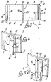
- a modular eiement gradually indicated at 1 comprises amain ' body 2 which is composed of a tubular portion 3, for example with a circular cross-section, which has a first base 4 and a second base 5 parallel to each other and being both orthogonal to the main axis of the tubular portion 3.
- the tubular portion 3 has an outer surface 6, for example substantially cylindrical, defining a pair of male connection elements 7 and a pair offemale connection elements 8 projecting therefrom.
- connection elements 7 and 8 are equidistant from each other, at an angle of substantially 90°, and each male connection element 7 extends in a diametrically opposite direction to a female connection element 8.
- Each male connection element 7, as shown best in Figure 4 comprises a flat ribbing 9 which extends radially from the outer surface 6 and has a first edge 10 parallel and substantially aligned to the first base 4, and a second edge 11 comprising a first inner section 12 parallel and aligned to the second base 5 and a second outer section 13 which is bent and depressed with respect to the second base 5.
- a substantially cylindrical enlargement 15 is formed, suitably parallel to the main axis of the tubular portion 3.
- the enlargement 15 forms a rounded end 16 whereas, on the opposite side, at the second edge 11, a flat end 17 is formed.
- Each female connection element is composed of a substantially tubular lug 18, suitably arranged with its longitudinal axis parallel to the cylindrical enlargements 15.
- the lug 18, which defines on its interior a seat 19 for insertion of a male connection element belonging to an adjacent modular element, has an open end 20 advantageously parallel and in alignment with the second base 5 of the tubular portion 3, and on the opposite side, a closed end 21 which protrudes from the plane defined bythefirst base 4.
- the lug 18, on the side opposite to the open end 20, is tapered externally with sloping faces 22 which converge toward the closed end 21 thereby imparting to the closed end 21 an outer polygonal contour, for example a quadrangular one.
- the lug 18 has, on the side diametrically opposite to the outer surface 6 of the tubular portion 3, a longitudinal slit 23 which extends from the open end 20 towards the closed end 21 at least as far as the same level of the first edge 10 which, in this specific case, coincides with that of the first base 4.
- the lateral wall 24 of the seat 19 defines stop elevations suitablyformed of a pair of rounded elevations 25 which protrude slightly toward the inside of the seat 19.
- Figure 1 shows four embodiments of the modular element which, in relation to the particular shape of the main body, can be particularly advantageous and are equally effective; in particular the reference numeral 26 indicates a modular element the main body whereof is composed of a tubular prismatic portion 27 with quadrangular cross-section, whilst the numeral 28 designates a modular element which has a different tubular prismatic portion 29 with octagonal cross-section.
- the male and female connection elements extend from the outer vertices of the respective tubular prismatic portions, 27 and 29, each male element is arranged, with respect to the main axis of the prismatic portion, symmetrically of a corresponding female element present on the opposite vertex.
- main body 31 whereof has, at one of the bases, a bevel which originates an inclined annulus 32, for example, sloping inwardly.
- the tubular elements may be closed internally by a bottom or an inner septum, having a flat or any other desired shape; such closure elements may be manufactured at the same time of the main body and thereby fixed with the latter or attached to the modular elements subsequently to their production, and completely or partly shut off the central hole of the tubular elements, possibly by projecting outwardly of their bases.
- the combined elements are used, by connecting them regularly side-by-side along mutually perpendicular directions so as to form a wall or another surface of any size.
- the rounded end 16 of the male connection elements 7 is inserted into the open end 20 of the female connection elements 8 of an adjacent modular element; the rounded end 16, on engaging with the rounded elevations 25, brings about a slight elastic deformation of the lug 18 to permit the insertion into the seat 19 of the whole enlargement 15, causing the ribbing 9 to slide in the longitudinal slit 23.
- the enlargement 15 is pushed into the seat 19 until the flat end 17, by moving past the rounded elevations 25, allows the lug 18 to return elastically to the indeformed rest position while the elevations 25 engage with the flat end 17.
- each individual modular element 1 there may be connected the corresponding male connection elements 7 of the adjacent modular elements.
- connection elements with male connection elements 7 and female connection elements 8 arranged on the opposite side from the main body 2, makes it possible to divide the panels into two or more parts along parallel lines to the alignment of the modular elements 1.
- modular elements according to the invention lend well to quick combination of non-structural surfaces, such as false ceilings, partition walls or covering walls, etc. without any constructional or assembly complications.
- modular elements described which lends themselves well for fabrication with normal manufacturing techniques, for example, by molding from a plastic material, may be made indifferently from both an opaque and transparent material as well as a translucid one in an unlimited range of colors and hues for the purpose of adjusting its chromatic effects to an unlimited number of possible uses.
- opaque elements of a dark color which may possibly have a closed main body 2, to emphasize an effect of space separation, or to use transparent or translucid modules in walls through which a large amount of light is sought; it will be possible in the latter application to use, for example, colored transparent elements thereby the light may cause new and particular coloring effects.
- composition is made possible of surfaces with differently colored areas distinctly separated from one another.
- connection system particularly advantageous is the use of tubular shapes, both internally closed and open, which, in addition to a beneficial structural influence, well combining with the appearance taken by the connection elements, bring about a specific aesthetic appearance due to the regular alternation of like forms with different dimension so as to lead to an appealing and proportioned overall result.
Landscapes
- Engineering & Computer Science (AREA)
- Architecture (AREA)
- Civil Engineering (AREA)
- Structural Engineering (AREA)
- Physics & Mathematics (AREA)
- Electromagnetism (AREA)
- Finishing Walls (AREA)
- Joining Of Building Structures In Genera (AREA)
Claims (6)
Applications Claiming Priority (2)
| Application Number | Priority Date | Filing Date | Title |
|---|---|---|---|
| IT3072585U | 1985-06-14 | ||
| IT8530725U IT207178Z2 (it) | 1985-06-14 | 1985-06-14 | Elemento modulare componibile particolarmente per l'allestimento di controsoffittature, piani divisori e pareti non strutturali in genere. |
Publications (2)
| Publication Number | Publication Date |
|---|---|
| EP0205109A1 EP0205109A1 (fr) | 1986-12-17 |
| EP0205109B1 true EP0205109B1 (fr) | 1990-04-25 |
Family
ID=11231438
Family Applications (1)
| Application Number | Title | Priority Date | Filing Date |
|---|---|---|---|
| EP86107656A Expired EP0205109B1 (fr) | 1985-06-14 | 1986-06-05 | Elément modulaire, en particulier pour faux plafonds, cloison de séparation et murs non-porteurs |
Country Status (4)
| Country | Link |
|---|---|
| US (1) | US4715158A (fr) |
| EP (1) | EP0205109B1 (fr) |
| DE (1) | DE3670662D1 (fr) |
| IT (1) | IT207178Z2 (fr) |
Families Citing this family (3)
| Publication number | Priority date | Publication date | Assignee | Title |
|---|---|---|---|---|
| US5274970A (en) * | 1992-04-07 | 1994-01-04 | Roberts Raymond P | Freestanding partition system |
| US9206599B2 (en) * | 2007-02-02 | 2015-12-08 | Les Materiaux De Construction Oldcastle Canada, Inc. | Wall with decorative facing |
| PL2959065T3 (pl) | 2013-02-25 | 2024-04-08 | Les Matériaux De Construction Oldcastle Canada, Inc. | Zestaw ścianowy |
Family Cites Families (7)
| Publication number | Priority date | Publication date | Assignee | Title |
|---|---|---|---|---|
| US910801A (en) * | 1907-11-20 | 1909-01-26 | Anton C Eggers | Tiled floor or wall. |
| US2900495A (en) * | 1957-04-30 | 1959-08-18 | Zwick Franz | Louver construction for lighting fixtures |
| FR1467702A (fr) * | 1966-02-09 | 1967-01-27 | éléments ajourés en matière plastique pour la construction de parois, principalement pour le bâtiment et la décoration | |
| FR2180590A1 (fr) * | 1972-04-21 | 1973-11-30 | Rivinox | |
| DE2651223A1 (de) * | 1976-11-10 | 1978-05-18 | Horst Dobner | Wand- und/oder deckenverkleidung |
| FR2466578A1 (fr) * | 1979-09-28 | 1981-04-10 | Manzelli Giorgio | Element modulaire pour la fabrication de faux plafonds composites |
| DE3118487A1 (de) * | 1981-05-09 | 1982-11-25 | Reinhard 7500 Karlsruhe Juraschek | Verbundsystem zum errichten von abgrenzungen und verbundstein fuer dieses system |
-
1985
- 1985-06-14 IT IT8530725U patent/IT207178Z2/it active
-
1986
- 1986-06-05 DE DE8686107656T patent/DE3670662D1/de not_active Expired - Lifetime
- 1986-06-05 EP EP86107656A patent/EP0205109B1/fr not_active Expired
- 1986-06-09 US US06/872,331 patent/US4715158A/en not_active Expired - Fee Related
Also Published As
| Publication number | Publication date |
|---|---|
| IT8530725V0 (it) | 1985-06-14 |
| US4715158A (en) | 1987-12-29 |
| EP0205109A1 (fr) | 1986-12-17 |
| DE3670662D1 (de) | 1990-05-31 |
| IT207178Z2 (it) | 1987-12-14 |
Similar Documents
| Publication | Publication Date | Title |
|---|---|---|
| US2972833A (en) | Plastic block assembly | |
| US2814159A (en) | Building unit and assembly for toys and the like | |
| US2861388A (en) | Structural toy and model building set | |
| US4318945A (en) | Underwater aquarium decoration assembly | |
| US5288047A (en) | Joiner of decorative light bulb | |
| US7044825B2 (en) | Panel and girder system for construction toy | |
| US4977648A (en) | Device at a snap-in lock | |
| US5904019A (en) | Thermoplastic building blocks | |
| US4890206A (en) | Christmas light set compiler | |
| AU1652692A (en) | Constructional toys | |
| EP2451548A1 (fr) | Ensemble de construction pour maisons-jouets | |
| WO1991013663A1 (fr) | Systeme d'elements structurels | |
| US2248117A (en) | Electric lighted ornamental device | |
| US4253267A (en) | Nativity scene housing construction | |
| EP0205109B1 (fr) | Elément modulaire, en particulier pour faux plafonds, cloison de séparation et murs non-porteurs | |
| GB2118447A (en) | Block toy | |
| US20200139259A1 (en) | Customizable Stackable Modular Construction System | |
| US3650080A (en) | Panel structure and assembly | |
| KR100285973B1 (ko) | 상호 결합 가능 요소들을 갖는 조립 세트 | |
| US4454698A (en) | Modular member for forming composite false-ceilings | |
| JPH0530451Y2 (fr) | ||
| US20090130947A1 (en) | Toy building set | |
| EP0506354A1 (fr) | Assemblage continu et décoratif des éléments composables | |
| US5934785A (en) | Structure of a light | |
| US3658203A (en) | Bottle cap |
Legal Events
| Date | Code | Title | Description |
|---|---|---|---|
| PUAI | Public reference made under article 153(3) epc to a published international application that has entered the european phase |
Free format text: ORIGINAL CODE: 0009012 |
|
| AK | Designated contracting states |
Kind code of ref document: A1 Designated state(s): DE FR GB |
|
| 17P | Request for examination filed |
Effective date: 19870610 |
|
| 17Q | First examination report despatched |
Effective date: 19881025 |
|
| GRAA | (expected) grant |
Free format text: ORIGINAL CODE: 0009210 |
|
| AK | Designated contracting states |
Kind code of ref document: B1 Designated state(s): DE FR GB |
|
| REF | Corresponds to: |
Ref document number: 3670662 Country of ref document: DE Date of ref document: 19900531 |
|
| ET | Fr: translation filed | ||
| PLBE | No opposition filed within time limit |
Free format text: ORIGINAL CODE: 0009261 |
|
| STAA | Information on the status of an ep patent application or granted ep patent |
Free format text: STATUS: NO OPPOSITION FILED WITHIN TIME LIMIT |
|
| 26N | No opposition filed | ||
| PGFP | Annual fee paid to national office [announced via postgrant information from national office to epo] |
Ref country code: GB Payment date: 19910605 Year of fee payment: 6 |
|
| PGFP | Annual fee paid to national office [announced via postgrant information from national office to epo] |
Ref country code: DE Payment date: 19910626 Year of fee payment: 6 |
|
| PGFP | Annual fee paid to national office [announced via postgrant information from national office to epo] |
Ref country code: FR Payment date: 19910627 Year of fee payment: 6 |
|
| PG25 | Lapsed in a contracting state [announced via postgrant information from national office to epo] |
Ref country code: GB Effective date: 19920605 |
|
| GBPC | Gb: european patent ceased through non-payment of renewal fee |
Effective date: 19920605 |
|
| PG25 | Lapsed in a contracting state [announced via postgrant information from national office to epo] |
Ref country code: FR Effective date: 19930226 |
|
| PG25 | Lapsed in a contracting state [announced via postgrant information from national office to epo] |
Ref country code: DE Effective date: 19930302 |
|
| REG | Reference to a national code |
Ref country code: FR Ref legal event code: ST |