EP0205310A2 - Auspuffbremse - Google Patents
Auspuffbremse Download PDFInfo
- Publication number
- EP0205310A2 EP0205310A2 EP86304260A EP86304260A EP0205310A2 EP 0205310 A2 EP0205310 A2 EP 0205310A2 EP 86304260 A EP86304260 A EP 86304260A EP 86304260 A EP86304260 A EP 86304260A EP 0205310 A2 EP0205310 A2 EP 0205310A2
- Authority
- EP
- European Patent Office
- Prior art keywords
- exhaust gas
- valve gate
- exhaust
- piston rod
- gate
- Prior art date
- Legal status (The legal status is an assumption and is not a legal conclusion. Google has not performed a legal analysis and makes no representation as to the accuracy of the status listed.)
- Granted
Links
Images

Classifications
-
- F—MECHANICAL ENGINEERING; LIGHTING; HEATING; WEAPONS; BLASTING
- F02—COMBUSTION ENGINES; HOT-GAS OR COMBUSTION-PRODUCT ENGINE PLANTS
- F02D—CONTROLLING COMBUSTION ENGINES
- F02D9/00—Controlling engines by throttling air or fuel-and-air induction conduits or exhaust conduits
- F02D9/08—Throttle valves specially adapted therefor; Arrangements of such valves in conduits
- F02D9/12—Throttle valves specially adapted therefor; Arrangements of such valves in conduits having slidably-mounted valve members; having valve members movable longitudinally of conduit
- F02D9/14—Throttle valves specially adapted therefor; Arrangements of such valves in conduits having slidably-mounted valve members; having valve members movable longitudinally of conduit the members being slidable transversely of conduit
-
- F—MECHANICAL ENGINEERING; LIGHTING; HEATING; WEAPONS; BLASTING
- F02—COMBUSTION ENGINES; HOT-GAS OR COMBUSTION-PRODUCT ENGINE PLANTS
- F02D—CONTROLLING COMBUSTION ENGINES
- F02D9/00—Controlling engines by throttling air or fuel-and-air induction conduits or exhaust conduits
- F02D9/04—Controlling engines by throttling air or fuel-and-air induction conduits or exhaust conduits concerning exhaust conduits
- F02D9/06—Exhaust brakes
-
- Y—GENERAL TAGGING OF NEW TECHNOLOGICAL DEVELOPMENTS; GENERAL TAGGING OF CROSS-SECTIONAL TECHNOLOGIES SPANNING OVER SEVERAL SECTIONS OF THE IPC; TECHNICAL SUBJECTS COVERED BY FORMER USPC CROSS-REFERENCE ART COLLECTIONS [XRACs] AND DIGESTS
- Y10—TECHNICAL SUBJECTS COVERED BY FORMER USPC
- Y10T—TECHNICAL SUBJECTS COVERED BY FORMER US CLASSIFICATION
- Y10T137/00—Fluid handling
- Y10T137/8593—Systems
- Y10T137/87265—Dividing into parallel flow paths with recombining
- Y10T137/87378—Second valve assembly carried by first valve head
Definitions
- This invention relates to a sliding gate assembly for an exhaust brake.
- Exhaust brakes are known to be adapted to be specifically located in the exhaust system of an internal combustion engine such that a back pressure of exhaust gases is created within the engine upon closure of a valve gate of the exhaust brake, thus utilising the power of the engine to enhance engine braking when the engine is normally operative for propelling a road vehicle, such as a commercial vehicle.
- Exhaust brakes are generally located in front of the muffler box of an exhaust system, relative to the flow of air through the exhaust system, as close to the outlet manifold of the internal combustion engine as possible, and often mounted directly onto the turbo charger.
- Another method of overcoming this problem has been to sense manifold pressure through a pressure valve and either to bleed off the air to a hydraulic cylinder controlling the gate, or in the case of a double acting cylinder, introduce air into the cylinder in front of the operative piston as well, thus taking off the exhaust brake. Because of the high tenperatures and carbon built-up this method has not been successful.
- a slidable gate assembly for an exhaust brake having a housing withaligned inlet and outlet apertures which allow the passage of exhaust gas through the housing, the slidable gate assembly conprising a valve gate having an exhaust gas relief passage therethrough and, being arranged to be slidable in the housing for controlling the flow of the exhaust gas through the inlet and outlet apertures of the said housing, a piston rod connected with the valve gate for moving the valve gate, closure means mounted on the piston rod for opening and closing the exhaust gas relief passage in the valve gate, and biasing means for biasing the closure means towards a closed condition of the exhaust gas relief passage when the valve gate closes the exhaust gas passage through the exhaust brake, wherein the piston rod is movable relative to the valve gate to open the exhaust gas relief passage through the valve gate in dependence upon the force applied by the biasing means.
- the closure member is slidable on the valve gate to close the exhaust gas relief passage therethrough.
- the closure means is mounted in a recess in one face of the valve gate.
- a further recess is provided in the opposite face of the valve gate to that having the first mentioned recess, the exhaust gas relief passage being located in a camon wall separating the first mentioned and further recesses.
- the closure means comprises plate slidable in the first mentioned recess to close the exhaust gas passage.
- the plate is preferably freely movable on the the piston rod, although, in an alternative embodiment the plate can be fixed to the end of the piston rod.
- a seal housing is located at the end of the piston rod remote from that end at which the valve gate is mounted and an end plate fixed to the end of the piston rod having the seal housing such that the seal housing is located against the end plate between the end plate and the valve gate.
- the biasing means is a spring, such as a coil spring, which is mounted around the piston rod between a flange on the piston rod and a seal housing movably located on the piston rod at the end of the piston rod remote from the valve gate.
- an exhaust brake including a housing with aligned inlet and outlet apertures which allow the passage of exhaust gas through the housing, and a slidable gate assembly comprising a valve gate having an exhaust gas relief passage therethrough and being arranged to be slidable in the housing for controlling the flow of exhaust gas throught the inlet and outlet apertures of the said housing, a piston rod connected with the valve gate for moving the valve gate, closure means mounted on the piston rod for opening and closing the exhaust gas relief passage in the valve gate, and biasing means for biasing the closure means towards a closed condition of the exhaust gas relief passage when the valve gate closes the exhaust gas passage through the exhaust brake, wherein the piston rod is movable relative to the valve gate to open the exhaust gas relief passage through the valve gate in dependance upon the force applied by the biasing means.
- the biasing means comprises a spring which in a closed position of the valve gate relative to the said apertures of the exhaust brake body, is effective to close the relief passage in the valve gate.
- the spring is mounted at one end of the piston rod.
- the closure means is mounted on the opposite end of the piston rod remote from that end at which the spring is mounted.
- Figs. 1 and 2 show one known exhaust brake which is arranged for fitment in an exhaust nanifold or pipe system of round cross-section.
- a valve closure gate 15 slidably mounted in the housing has a loose sliding fit in the valve chamber and is capable of sealing engagement with inner surfaces of either of the walls 11 and 12.
- the gate is movable between the position shown in Figs. 1 and 2 in which the gate is clear of the apertures 13 and 14 to leave the exhaust passage substantially unobstructed, and a position to the right (Figs.1 and 2) in which the gate closes the apertures 13 and 14 to close the exhaust passage.
- the walls 11 and 12 are adapted to be fitted, by their outside surfaces, to suitable flange joints in the exhaust system.
- the valve chamber of the hollow body 10 opens to an end face of the body which is closed by a removable plate 16 which also forms an end stop for the movement of the valve gate 15 to the open position of the exhaust brake.
- a single acting fluid pressure operated piston and cylinder device, indicated generally at 17, is mounted by flange on the body 10 outside the plate 16. Bolts 18 and 19 which are screw threaded into the body 10 serve to locate and hold the device 17 and the plate 16 on the body 10.
- the fluid pressure device 17 conprises a piston 20 and a piston rod 21 which extends through the plate 16 into a bore 22 in the valve gate 15.
- the valve gate 15 is attached to the piston rod 21 by a cross pin 23 securely fixed in the end of the piston rod 21 and is located in a cross bore 24 in the valve gate 15.
- Both the bores 22 and 24 are a generous clearance fit over the piston rod 21 and the pin 23 respectively, and allow the valve gate 15 to float on the piston rod 21 during motion of the gate between the open and closed positions thus to allow exhaust gas pressure to drive it into sealing engagement with the inside surface of the respective wall 11 and 12.
- the fluid pressure device 17 also includes a return spring 25 arranged around the piston rod 21 behind the piston 20 to bias the piston and consequently the valve gate 15 towards the open position thereof.
- valve gate 15 when fluid under pressure is supplied to the front face of the piston 20 through a port 26 the valve gate 15 is driven to the left, to close the apertures 13 and 14, whereas when the pressure is released from the device 17, the valve gate 15 is moved back to its open position by means of the spring 25.
- the spring 27 is only operative over the end of the stroke that closes the valve and provides additional spring force to overcome any initial resistance caused by any build up of carbon deposits on the valve at the beginning of an opening stroke.
- a spring 30 is located between the scraper rings to keep them in position against the plate 16 and the flange of the device 17, respectively.
- an adjustable abutment in the form of a set screw 43 is provided in the body to engage the valve gate 15 in its closed position affording sore adjustment of that position. Accordingly, the valve gate 15 may completely shut off the exhaust gas passage, or the set screw 43 can be adjusted so that in the closed position of the valve gate 15 the exhaust passage is not ccnpletely shut off but allows a controlled amount of the exhaust gas to flow through the valve.
- valve gate 15 By removing the device 17 and the plate 16 from the body 10 of the exhaust valve the valve gate 15 may be extracted for servicing without disturbing the mounting of the body 10 in the exhaust system.
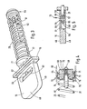
- Figs. 3 through 5 there is shown a slidable gate assembly and in these figures parts which are common with the exhaust brake of Figs. 1 and 2 are given like reference numerals. For the sake of simplicity only those parts of the slidable gate assembly which differ from the corresponding assembly of Figs. 1 and 2 will be described.
- the gate valve 15 of the slidable gate assembly shown in Figs. 3 through 5 is provided with opposed planar surfaces 48,49.
- a recess 50 is provided in gate surface 49 and extends into the body of valve gate 15 leaving a relatively thin wall portion 51 separating the recess 50 from the opposite side 48 of the valve gate.
- a further recess 54 is provided in gate surface 48 and lies adjacent to recess 50, being separated by a common side wall 55 and communicating one with the other of an elongate aperture 56 in the common recess wall 55.
- Piston rod 21 extends through the gate 15 into the recess 54 and is provided with a fixed cross-pin 57 which prevents removal of the piston rod relative to the valve gate 15.
- a pressure plate 60 is located in the recess 54 and is engageable with wall 55 to completely close the aperture 56 therethrough.
- the plate 60 is mounted at one end of piston rod 21 for sliding movement within the recess 54 to allow opening and closing of the aperture 52.
- the plate 60 is loosely connected with the piston rod 21 for movement in both axial and transverse directions relative to the longitudinal axis of the piston rod to ensure free movement of the plate 60 relative to the piston rod under high tenperature and carbon coated conditions. More particularly the end of the piston rod 21 on which the gate 15 is mounted, has an end portion 58 of reduced diameter which extends through a corresponding aperture in plate 60 and aperture 56 As shown in Fig. 5 the plate 60 abuts a shoulder 59 defined by the change in diameter between end portion 58 and the remainder of the piston rod. The shoulder 59 serves to push the plate 60 towards aperture 56 upon movement of the piston rod 21 to the left in Fig. 6.
- Spring 25 is the main spring which directly effects movement of the gate 15 from the exhaust aperture. 13,14 of the body 10 as shown with reference to the exhaust brake of Figs. 1 and 2.
- Spring 61 ismounted on the piston rod 21 towards the end of the rod remote from that connected with the gate 15.
- the spring 61 is retained between a radially outstanding flange 62, such as a washer held by a cir-clip, and a piston seal housing 63 which supports a hydraulic seal 64 in contact with the inner surface of a cylindrical housing 65 of the piston and cylinder device 17 mounted on plate 16, and partially shown in Fig. 4.
- the spring 61 has been found to be subject to a maximum tenperature of 107°C, well below the setting temperature of the spring.
- the piston seal housing 63 has a bore 66 therethrough through which the piston rod 21 extends to an end plate 67 which is fixed by bolt 68 to the end of the piston rod but is movable relative to the seal housing.
- the bore 66 has three regions of differing internal diameters.
- the first region 70 has a diameter substantially identical to the outside diameter of the piston rod 21.
- the second region 71 is of slightly enlarged diameter and sealing 0-rings 72 with annular packing washers 73 are located in the space rovided between the seal housing and the piston rod.
- a retaining washer 74 is located in the third region 75 for engagment with the spring 61.
- the spring 25 engages in an annular circumferential recess 76 of the seal housing.
- the manifold pressure is dependent upon the conpression force of the spring 61 which being located in the device 77 at the end of the piston rod 21 remote from the gate 15 is subject to tenperatures which are well below the setting temperatures of the spring 61, even when the gate 15 is subjected to its highest operating tenperature.
- the side wall of the recess 50 opposite to wall 55 is sloped at an angle of 45° to assist in directing the exhaust gas flow towards the aperture 56 in the wall 55.
- the pressure plate 60 is fixed to the end of the shaft 21 at a position suitable for opening and closing aperture 56, such as in the position shown in Fig. 5
Landscapes
- Engineering & Computer Science (AREA)
- Chemical & Material Sciences (AREA)
- Combustion & Propulsion (AREA)
- Mechanical Engineering (AREA)
- General Engineering & Computer Science (AREA)
- Control Of Throttle Valves Provided In The Intake System Or In The Exhaust System (AREA)
- Braking Arrangements (AREA)
- Valve Device For Special Equipments (AREA)
- Memory System Of A Hierarchy Structure (AREA)
- Cold Cathode And The Manufacture (AREA)
- Portable Nailing Machines And Staplers (AREA)
Priority Applications (1)
| Application Number | Priority Date | Filing Date | Title |
|---|---|---|---|
| AT86304260T ATE52573T1 (de) | 1985-06-07 | 1986-06-04 | Auspuffbremse. |
Applications Claiming Priority (2)
| Application Number | Priority Date | Filing Date | Title |
|---|---|---|---|
| GB8514447A GB8514447D0 (en) | 1985-06-07 | 1985-06-07 | Sliding gate assembly |
| GB8514447 | 1985-06-07 |
Publications (3)
| Publication Number | Publication Date |
|---|---|
| EP0205310A2 true EP0205310A2 (de) | 1986-12-17 |
| EP0205310A3 EP0205310A3 (en) | 1987-04-08 |
| EP0205310B1 EP0205310B1 (de) | 1990-05-09 |
Family
ID=10580353
Family Applications (1)
| Application Number | Title | Priority Date | Filing Date |
|---|---|---|---|
| EP19860304260 Expired - Lifetime EP0205310B1 (de) | 1985-06-07 | 1986-06-04 | Auspuffbremse |
Country Status (10)
| Country | Link |
|---|---|
| US (1) | US4669585A (de) |
| EP (1) | EP0205310B1 (de) |
| AT (1) | ATE52573T1 (de) |
| AU (1) | AU579802B2 (de) |
| CA (1) | CA1277351C (de) |
| DE (1) | DE3671067D1 (de) |
| ES (1) | ES8704239A1 (de) |
| GB (1) | GB8514447D0 (de) |
| NZ (1) | NZ216452A (de) |
| PT (1) | PT82729B (de) |
Cited By (1)
| Publication number | Priority date | Publication date | Assignee | Title |
|---|---|---|---|---|
| WO1994029583A1 (en) * | 1993-06-16 | 1994-12-22 | Hersham Valves Limited | Exhaust brake |
Families Citing this family (15)
| Publication number | Priority date | Publication date | Assignee | Title |
|---|---|---|---|---|
| JPH0517392Y2 (de) * | 1987-09-26 | 1993-05-11 | ||
| JP2503353Y2 (ja) * | 1987-11-18 | 1996-06-26 | 臼井国際産業株式会社 | スライド式排気ブレ―キ装置 |
| JP2660418B2 (ja) * | 1988-03-11 | 1997-10-08 | 臼井国際産業株式会社 | スライド式排気ブレーキ装置 |
| US5435347A (en) * | 1993-07-22 | 1995-07-25 | Donaldson Company, Inc. | Exhaust systems for motorized vehicles |
| US5445248A (en) * | 1994-03-07 | 1995-08-29 | Jenara Enterprises Ltd. | Exhaust brake |
| US5785014A (en) * | 1995-12-22 | 1998-07-28 | Cornwell; Gary R. | Expansion chamber for two-cycle engine |
| US6053146A (en) * | 1996-10-16 | 2000-04-25 | Paul E. Arlton | Model aircraft engine with exhaust control mechanism |
| FR2777945B1 (fr) * | 1998-04-22 | 2000-06-16 | Fowa | Dispositif ralentiseur monte dans le circuit d'echappement des gaz d'un vehicule equipe d'un moteur a combustion |
| GB2355764B (en) | 1999-10-29 | 2003-12-03 | Hersham Valves Ltd | Sliding gate exhaust brake assembly |
| US6286307B1 (en) * | 2000-02-09 | 2001-09-11 | Robert L. Feeny | Exhaust gas control device for an engine |
| CA2453593C (en) * | 2003-12-16 | 2013-05-28 | Jenara Enterprises Ltd. | Pressure relief exhaust brake |
| KR100577561B1 (ko) * | 2004-01-12 | 2006-05-08 | 삼성전자주식회사 | 반도체 제조 설비의 배기압력 제어장치 |
| US7350502B2 (en) * | 2004-11-22 | 2008-04-01 | Jacobs Vehicle Systems, Inc. | Apparatus and method for controlling exhaust pressure |
| TWM282036U (en) * | 2005-07-27 | 2005-12-01 | Ming-Hung Jeng | Improved piston-type pressure relief valve for turbine exhaust |
| US7744062B2 (en) * | 2007-03-09 | 2010-06-29 | Fisher Controls International Llc | Apparatus to vary effective spring rate for use in diaphragm actuators |
Family Cites Families (14)
| Publication number | Priority date | Publication date | Assignee | Title |
|---|---|---|---|---|
| GB191329906A (en) * | 1913-09-13 | 1914-03-05 | Emrich J | Improvements in Asparagus Tongs. |
| US1752229A (en) * | 1925-11-07 | 1930-03-25 | Lee D Brueckel | Compression brake |
| DE553249C (de) * | 1929-12-08 | 1932-06-23 | Schaeffer & Budenberg G M B H | Entlastungsvorrichtung fuer Absperrorgane |
| US1932471A (en) * | 1931-04-06 | 1933-10-31 | Hughes Tool Co | Relief device for valves |
| US2190412A (en) * | 1939-08-08 | 1940-02-13 | Paul E Mcmurry | Pipe line pressure neutralizer |
| US2745517A (en) * | 1953-04-20 | 1956-05-15 | Kalamazoo Tank & Silo Company | Dashpot cylinder |
| GB822078A (en) * | 1956-03-02 | 1959-10-21 | Haller Richard | Engine brake for internal combustion engines, in particular such of powered vehicles |
| DE1153208B (de) * | 1959-04-28 | 1963-08-22 | Maschf Augsburg Nuernberg Ag | Auspuffbremse fuer Brennkraftmaschinen |
| US4054156A (en) * | 1975-02-24 | 1977-10-18 | The Weatherhead Company | Exhaust brake valve |
| DE2519376C2 (de) * | 1975-04-30 | 1983-09-22 | Kraftwerk Union AG, 4330 Mülheim | Steuerbares Ventil für eine Frischdampfleitung einer Kernreaktoranlage |
| US4408627A (en) * | 1975-05-08 | 1983-10-11 | Harris Victor A | Exhaust brake valve unit |
| US4205704A (en) * | 1978-10-04 | 1980-06-03 | Dana Corporation | Exhaust brake valve |
| US4509549A (en) * | 1982-10-12 | 1985-04-09 | The United States Of America As Represented By The Secretary Of The Navy | Hydraulic powered gate valve |
| AU591733B2 (en) * | 1985-12-26 | 1989-12-14 | Jidosha Kiki Co. Ltd. | Exhaust gas brake system |
-
1985
- 1985-06-07 GB GB8514447A patent/GB8514447D0/en active Pending
- 1985-08-28 US US06/770,391 patent/US4669585A/en not_active Expired - Lifetime
-
1986
- 1986-06-04 AT AT86304260T patent/ATE52573T1/de not_active IP Right Cessation
- 1986-06-04 DE DE8686304260T patent/DE3671067D1/de not_active Expired - Fee Related
- 1986-06-04 EP EP19860304260 patent/EP0205310B1/de not_active Expired - Lifetime
- 1986-06-06 CA CA 510994 patent/CA1277351C/en not_active Expired - Lifetime
- 1986-06-06 ES ES555807A patent/ES8704239A1/es not_active Expired
- 1986-06-06 AU AU58471/86A patent/AU579802B2/en not_active Ceased
- 1986-06-06 NZ NZ21645286A patent/NZ216452A/xx unknown
- 1986-06-06 PT PT82729A patent/PT82729B/pt not_active IP Right Cessation
Cited By (1)
| Publication number | Priority date | Publication date | Assignee | Title |
|---|---|---|---|---|
| WO1994029583A1 (en) * | 1993-06-16 | 1994-12-22 | Hersham Valves Limited | Exhaust brake |
Also Published As
| Publication number | Publication date |
|---|---|
| AU579802B2 (en) | 1988-12-08 |
| ES8704239A1 (es) | 1987-03-16 |
| PT82729A (en) | 1986-07-01 |
| ATE52573T1 (de) | 1990-05-15 |
| AU5847186A (en) | 1986-12-11 |
| EP0205310A3 (en) | 1987-04-08 |
| NZ216452A (en) | 1988-07-28 |
| EP0205310B1 (de) | 1990-05-09 |
| ES555807A0 (es) | 1987-03-16 |
| PT82729B (pt) | 1992-07-31 |
| US4669585A (en) | 1987-06-02 |
| DE3671067D1 (de) | 1990-06-13 |
| GB8514447D0 (en) | 1985-07-10 |
| CA1277351C (en) | 1990-12-04 |
Similar Documents
| Publication | Publication Date | Title |
|---|---|---|
| EP0205310B1 (de) | Auspuffbremse | |
| US4054156A (en) | Exhaust brake valve | |
| US4585207A (en) | Expanding gate valve with pneumatic actuator | |
| US5214920A (en) | Turbocharger apparatus | |
| US6041804A (en) | Subsea valve actuator and method | |
| CA1273328A (en) | Dual stage hydraulic actuator for expanding gate valve | |
| US4491154A (en) | Double acting pilot valve | |
| US5116252A (en) | In-line sleeve valve having velocity guide pressure equalization and drive assembly with improved drive pin mountings | |
| US5291918A (en) | Safety valve actuator assembly | |
| US5231831A (en) | Turbocharger apparatus | |
| US4883083A (en) | Relief valve assembly; piston member from same and filter head assembly incorporating same | |
| US4093046A (en) | Exhaust braking apparatus | |
| EP0678657B1 (de) | Turbolader | |
| US4553648A (en) | Exhaust brake apparatus of sliding type | |
| US4501238A (en) | Engine air intake shut-off valve | |
| CN101103190B (zh) | 控制排气压力的设备和方法 | |
| US5787858A (en) | Engine brake with controlled valve closing | |
| US4639196A (en) | Fluid control valve | |
| EP0704018B1 (de) | Auspuffbremse | |
| US5070900A (en) | Safety valve actuator assembly | |
| EP0431459B1 (de) | Dreiwegventil mit Druckausgleichsventil | |
| US3253517A (en) | Transducer | |
| US4134543A (en) | Snap action thermally responsive fluid control valve | |
| CA1333354C (en) | Safety valve actuator assembly | |
| HK1002733B (en) | Exhaust brake |
Legal Events
| Date | Code | Title | Description |
|---|---|---|---|
| PUAI | Public reference made under article 153(3) epc to a published international application that has entered the european phase |
Free format text: ORIGINAL CODE: 0009012 |
|
| AK | Designated contracting states |
Kind code of ref document: A2 Designated state(s): AT BE CH DE FR GB IT LI LU NL SE |
|
| PUAL | Search report despatched |
Free format text: ORIGINAL CODE: 0009013 |
|
| AK | Designated contracting states |
Kind code of ref document: A3 Designated state(s): AT BE CH DE FR GB IT LI LU NL SE |
|
| 17P | Request for examination filed |
Effective date: 19871123 |
|
| 17Q | First examination report despatched |
Effective date: 19880217 |
|
| GRAA | (expected) grant |
Free format text: ORIGINAL CODE: 0009210 |
|
| AK | Designated contracting states |
Kind code of ref document: B1 Designated state(s): AT BE CH DE FR GB IT LI LU NL SE |
|
| REF | Corresponds to: |
Ref document number: 52573 Country of ref document: AT Date of ref document: 19900515 Kind code of ref document: T |
|
| ITF | It: translation for a ep patent filed | ||
| REF | Corresponds to: |
Ref document number: 3671067 Country of ref document: DE Date of ref document: 19900613 |
|
| ET | Fr: translation filed | ||
| PLBE | No opposition filed within time limit |
Free format text: ORIGINAL CODE: 0009261 |
|
| STAA | Information on the status of an ep patent application or granted ep patent |
Free format text: STATUS: NO OPPOSITION FILED WITHIN TIME LIMIT |
|
| 26N | No opposition filed | ||
| ITTA | It: last paid annual fee | ||
| EPTA | Lu: last paid annual fee | ||
| EAL | Se: european patent in force in sweden |
Ref document number: 86304260.2 |
|
| PGFP | Annual fee paid to national office [announced via postgrant information from national office to epo] |
Ref country code: LU Payment date: 19980608 Year of fee payment: 13 |
|
| PGFP | Annual fee paid to national office [announced via postgrant information from national office to epo] |
Ref country code: AT Payment date: 19980615 Year of fee payment: 13 |
|
| PG25 | Lapsed in a contracting state [announced via postgrant information from national office to epo] |
Ref country code: LU Free format text: LAPSE BECAUSE OF NON-PAYMENT OF DUE FEES Effective date: 19990604 Ref country code: AT Free format text: LAPSE BECAUSE OF NON-PAYMENT OF DUE FEES Effective date: 19990604 |
|
| REG | Reference to a national code |
Ref country code: GB Ref legal event code: IF02 |
|
| PGFP | Annual fee paid to national office [announced via postgrant information from national office to epo] |
Ref country code: DE Payment date: 20020718 Year of fee payment: 17 |
|
| PGFP | Annual fee paid to national office [announced via postgrant information from national office to epo] |
Ref country code: FR Payment date: 20020719 Year of fee payment: 17 |
|
| PGFP | Annual fee paid to national office [announced via postgrant information from national office to epo] |
Ref country code: SE Payment date: 20020722 Year of fee payment: 17 Ref country code: CH Payment date: 20020722 Year of fee payment: 17 |
|
| PGFP | Annual fee paid to national office [announced via postgrant information from national office to epo] |
Ref country code: BE Payment date: 20020819 Year of fee payment: 17 |
|
| PG25 | Lapsed in a contracting state [announced via postgrant information from national office to epo] |
Ref country code: SE Free format text: LAPSE BECAUSE OF NON-PAYMENT OF DUE FEES Effective date: 20030605 |
|
| PG25 | Lapsed in a contracting state [announced via postgrant information from national office to epo] |
Ref country code: LI Free format text: LAPSE BECAUSE OF NON-PAYMENT OF DUE FEES Effective date: 20030630 Ref country code: CH Free format text: LAPSE BECAUSE OF NON-PAYMENT OF DUE FEES Effective date: 20030630 Ref country code: BE Free format text: LAPSE BECAUSE OF NON-PAYMENT OF DUE FEES Effective date: 20030630 |
|
| BERE | Be: lapsed |
Owner name: *HERSHAM VALVES LTD Effective date: 20030630 |
|
| PG25 | Lapsed in a contracting state [announced via postgrant information from national office to epo] |
Ref country code: DE Free format text: LAPSE BECAUSE OF NON-PAYMENT OF DUE FEES Effective date: 20040101 |
|
| EUG | Se: european patent has lapsed | ||
| REG | Reference to a national code |
Ref country code: CH Ref legal event code: PL |
|
| PG25 | Lapsed in a contracting state [announced via postgrant information from national office to epo] |
Ref country code: FR Free format text: LAPSE BECAUSE OF NON-PAYMENT OF DUE FEES Effective date: 20040227 |
|
| REG | Reference to a national code |
Ref country code: FR Ref legal event code: ST |
|
| PGFP | Annual fee paid to national office [announced via postgrant information from national office to epo] |
Ref country code: GB Payment date: 20040526 Year of fee payment: 19 |
|
| PGFP | Annual fee paid to national office [announced via postgrant information from national office to epo] |
Ref country code: NL Payment date: 20040630 Year of fee payment: 19 |
|
| PG25 | Lapsed in a contracting state [announced via postgrant information from national office to epo] |
Ref country code: IT Free format text: LAPSE BECAUSE OF NON-PAYMENT OF DUE FEES;WARNING: LAPSES OF ITALIAN PATENTS WITH EFFECTIVE DATE BEFORE 2007 MAY HAVE OCCURRED AT ANY TIME BEFORE 2007. THE CORRECT EFFECTIVE DATE MAY BE DIFFERENT FROM THE ONE RECORDED. Effective date: 20050604 Ref country code: GB Free format text: LAPSE BECAUSE OF NON-PAYMENT OF DUE FEES Effective date: 20050604 |
|
| PG25 | Lapsed in a contracting state [announced via postgrant information from national office to epo] |
Ref country code: NL Free format text: LAPSE BECAUSE OF NON-PAYMENT OF DUE FEES Effective date: 20060101 |
|
| GBPC | Gb: european patent ceased through non-payment of renewal fee |
Effective date: 20050604 |
|
| NLV4 | Nl: lapsed or anulled due to non-payment of the annual fee |
Effective date: 20060101 |