EP0205361A1 - Handbetätigte Schnapp-Schliesseinrichtung eines Miniaturschutzschalters - Google Patents
Handbetätigte Schnapp-Schliesseinrichtung eines Miniaturschutzschalters Download PDFInfo
- Publication number
- EP0205361A1 EP0205361A1 EP86400929A EP86400929A EP0205361A1 EP 0205361 A1 EP0205361 A1 EP 0205361A1 EP 86400929 A EP86400929 A EP 86400929A EP 86400929 A EP86400929 A EP 86400929A EP 0205361 A1 EP0205361 A1 EP 0205361A1
- Authority
- EP
- European Patent Office
- Prior art keywords
- spring
- link
- retaining plate
- lever
- handle
- Prior art date
- Legal status (The legal status is an assumption and is not a legal conclusion. Google has not performed a legal analysis and makes no representation as to the accuracy of the status listed.)
- Granted
Links
- 230000007246 mechanism Effects 0.000 title claims abstract description 26
- 230000005540 biological transmission Effects 0.000 claims abstract description 18
- 238000004146 energy storage Methods 0.000 claims abstract description 6
- 230000000903 blocking effect Effects 0.000 claims description 7
- 230000007935 neutral effect Effects 0.000 claims description 3
- 238000006386 neutralization reaction Methods 0.000 claims description 2
- 230000010287 polarization Effects 0.000 claims 1
- 208000031968 Cadaver Diseases 0.000 description 1
- 230000002457 bidirectional effect Effects 0.000 description 1
- 230000004048 modification Effects 0.000 description 1
- 238000012986 modification Methods 0.000 description 1
- 210000000056 organ Anatomy 0.000 description 1
- 238000000926 separation method Methods 0.000 description 1
Images

Classifications
-
- H—ELECTRICITY
- H01—ELECTRIC ELEMENTS
- H01H—ELECTRIC SWITCHES; RELAYS; SELECTORS; EMERGENCY PROTECTIVE DEVICES
- H01H5/00—Snap-action arrangements, i.e. in which during a single opening operation or a single closing operation energy is first stored and then released to produce or assist the contact movement
- H01H5/04—Energy stored by deformation of elastic members
- H01H5/14—Energy stored by deformation of elastic members by twisting of torsion members
- H01H5/16—Energy stored by deformation of elastic members by twisting of torsion members with auxiliary means for temporarily holding parts until torsion member is sufficiently strained
-
- H—ELECTRICITY
- H01—ELECTRIC ELEMENTS
- H01H—ELECTRIC SWITCHES; RELAYS; SELECTORS; EMERGENCY PROTECTIVE DEVICES
- H01H71/00—Details of the protective switches or relays covered by groups H01H73/00 - H01H83/00
- H01H71/10—Operating or release mechanisms
- H01H71/50—Manual reset mechanisms which may be also used for manual release
- H01H71/52—Manual reset mechanisms which may be also used for manual release actuated by lever
-
- H—ELECTRICITY
- H01—ELECTRIC ELEMENTS
- H01H—ELECTRIC SWITCHES; RELAYS; SELECTORS; EMERGENCY PROTECTIVE DEVICES
- H01H2300/00—Orthogonal indexing scheme relating to electric switches, relays, selectors or emergency protective devices covered by H01H
- H01H2300/046—Orthogonal indexing scheme relating to electric switches, relays, selectors or emergency protective devices covered by H01H using snap closing mechanisms
- H01H2300/048—Snap closing by latched movable contact, wherein the movable contact is held in a minimal distance from the fixed contact during first phase of closing sequence in which a closing spring is charged
Definitions
- the invention relates to an abrupt manual closing mechanism of a miniature circuit breaker with molded insulating boot comprising:
- the abrupt closing mechanisms of the kind mentioned generally require an interruption of the kinematic chain by systems of snap levers intended to cooperate directly with the contact-carrying arm, during the closing stroke of the lever. These known mechanisms are complicated and have a large size incompatible with the reduced volume of the housing.
- the object of the present invention is to provide a simple mechanism for abruptly closing the contacts of a power cut device, the actuation of which requires normal force without excessive hard point when the accumulator spring comes into action.
- the retaining plate comprises a light for guiding the transmission link, said light being provided with a boss serving as a stop for the link in the active position of the retaining plate.
- the kinematic chain drives the contact carrier arm at the start of the closing stroke to an intermediate position separated from the fixed contact by a gap (d) of small thickness, said intermediate position of the current carrier arm corresponding to the position hooking the rod on the boss of the light.
- the retaining plate is pivotally mounted in a bearing of the housing and is biased towards the active position by a biasing spring bearing on a flange situated opposite the bearing.
- the accumulator spring advantageously consists of a torsional torsion spring housed around the pivot axis of the handle in a cylindrical cavity in the body of the handle.
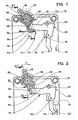
- an abrupt closing device 10 is incorporated in the control mechanism of an electric current cut-off device, in particular a miniature low-voltage circuit breaker with a molded insulating case 12.
- the mechanism of each pole comprises a tilting lever 14 for manual operation connected by a kinematic chain 16 of transmission to a contact arm 18 for supporting the movable contact 19, cooperating with a fixed contact 10.
- the kinematic chain 16 of the mechanism is described in detail in French Patent No. 2,344,950, but the triggering members of the mechanism have not been shown in FIGS. 1 to 4.
- the kinematic chain 16 comprises a rocker arm 22 rotatably mounted on a fixed axis 24.
- One of the branches 25 of the rocker arm 22 carries a pivot 26 on which the contact arm 18 is pivotally mounted, cooperating with a hooking stop belonging to the trigger lever (not shown).
- the contact arm 18 In the active position of the hooking stop, the contact arm 18 is locked on the rocker arm 22, so as to constitute a bidirectional connection between the lever 14 and the contact arm 18.
- the contact arm 18 In the unlocked position of the hooking stopper , following a triggering of the mechanism on fault, the contact arm 18 is unlocked relative to the rocker arm 22, causing the breaking of the mechanical connection between the lever 14 and the contact arm 18.
- An opening spring (not shown) Then causes separation of the contacts 19, 20, independently of the lever 14. The operation of such a mechanism is well known to specialists, and it is unnecessary to describe it in more detail.
- the snap closure device 10 is composed of a spring 30 energy accumulator housed in a cylindrical cavity 32 of the body 34 of the lever 14, and of a retaining plate 36, cooperating with the kinematic chain 16 of the mechanism.
- the tilting lever 14 is rotatably mounted between two extreme closing and opening positions on a fixed transverse axis 38 positioned in aligned bearings of the housing 12.
- the energy storage spring 30 is constituted by a torsional héiicoldai spring s' extending in the cavity 32 coaxially around the axis 38.
- One of the ends 31 of the accumulator spring 30 is engaged in a slot in the body 34 of the lever 14, while the other opposite end 33 is secured to an intermediate lever 40 for supporting a transmission link 42.
- the branch 44 of the rocker arm 22 located opposite the pivot 26 is attached to the rod 42, formed by a U-shaped bracket.
- One of the arms of the link 42 is articulated on the lever 40, pivotally mounted on the axis 38, and the other arm is guided inside a slot 46, formed in the retaining plate 36.
- the transmission link 42 and the intermediate lever 40 constitute a toggle arranged between the lever 14 and the rocker arm 22.
- the light 46 of the retaining plate 36 is provided with a boss 48, arranged to form an erasable stop, cooperating with the link 42.
- the body 34 of the lever 14 is equipped with an unlocking lug 50 moving in a circular trajectory, during the tilting of the lever 14.
- the retaining plate 36 is pivotally mounted on a shoulder or bearing 52 of the housing 12 so as to occupy an active locking position or a cleared unlocking position.
- the plate 36 has a flange 54 cooperating with a biasing spring 56 which biases the plate 36 in the counterclockwise direction towards the active position, allowing the connecting rod 42 to come into abutment against the boss 48 ( Figure 2) during the closing operation of the handle 14.
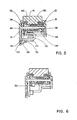
- the lug 50 of the body 34 serves as a drive member of the retaining plate 36 towards the erased position against the action of the biasing spring 56, causing the toggle 40, 42 to break, when the lever 14 reaches the end of the closing stroke (FIG. 3).
- the bias spring 56 is advantageously formed by a strand of the return spring of the trigger lock.
- a return spring 58 disposed between the housing 12 and the body 34 opposite the lever 40, biases the lever 14 towards the open position - ( Figure 1).
- the snap closure device 10 has a compact structure thanks to the coaxial arrangement of the accumulator spring 30, the lever 40 and the retaining plate 36 on the axis 38 of the lever 14.
- the arming of the energy storage spring 30 takes place during the continued pivoting movement of the lever 14 towards the position shown in FIG. 3.
- the blocking of the rod 42 by the retaining plate 36 hampers the movement of the kinematic connection, and the contact arm 18 remains stationary in the intermediate position of FIG. 2.
- the unlocking lug 50 drives the retaining plate 36 clockwise of a watch towards the erased position, against the force of the spring 56.
- the release of the link 42 authorizes the passage of the neutral point of the toggle joint, and the relaxation of the spring 30. All the energy stored in this last, by actuation of the lever 14 is thus returned to the rocker arm 22 of the kinematic link 16, causing a sudden closure of the contacts 19, 20, ( Figure 4).
- the transmission rod 42 is then positioned at the bottom of the light 46, and the retaining plate 36 remains biased in the position erased by the lug 50.
- the erasure of the boss 48 then authorizes a manual opening operation of the circuit breaker by making rotate la.manette 14 anti-clockwise to the position of Figure 1.
Landscapes
- Driving Mechanisms And Operating Circuits Of Arc-Extinguishing High-Tension Switches (AREA)
- Breakers (AREA)
- Keying Circuit Devices (AREA)
- Switch Cases, Indication, And Locking (AREA)
- Fuses (AREA)
Priority Applications (1)
| Application Number | Priority Date | Filing Date | Title |
|---|---|---|---|
| AT86400929T ATE50084T1 (de) | 1985-05-13 | 1986-04-28 | Handbetaetigte schnapp-schliesseinrichtung eines miniaturschutzschalters. |
Applications Claiming Priority (2)
| Application Number | Priority Date | Filing Date | Title |
|---|---|---|---|
| FR8507343A FR2581791B1 (fr) | 1985-05-13 | 1985-05-13 | Mecanisme de fermeture manuelle brusque d'un appareil de coupure de courant |
| FR8507343 | 1985-05-13 |
Publications (2)
| Publication Number | Publication Date |
|---|---|
| EP0205361A1 true EP0205361A1 (de) | 1986-12-17 |
| EP0205361B1 EP0205361B1 (de) | 1990-01-31 |
Family
ID=9319290
Family Applications (1)
| Application Number | Title | Priority Date | Filing Date |
|---|---|---|---|
| EP86400929A Expired - Lifetime EP0205361B1 (de) | 1985-05-13 | 1986-04-28 | Handbetätigte Schnapp-Schliesseinrichtung eines Miniaturschutzschalters |
Country Status (11)
| Country | Link |
|---|---|
| US (1) | US4687891A (de) |
| EP (1) | EP0205361B1 (de) |
| JP (1) | JP2510514B2 (de) |
| AT (1) | ATE50084T1 (de) |
| AU (1) | AU581396B2 (de) |
| CA (1) | CA1275139A (de) |
| DE (1) | DE3668724D1 (de) |
| ES (1) | ES8704670A1 (de) |
| FR (1) | FR2581791B1 (de) |
| PT (1) | PT82563B (de) |
| ZA (1) | ZA863450B (de) |
Cited By (3)
| Publication number | Priority date | Publication date | Assignee | Title |
|---|---|---|---|---|
| EP0458382A1 (de) * | 1990-05-21 | 1991-11-27 | Koninklijke Philips Electronics N.V. | Mehrpoliger Überlastschalter |
| EP0500138A1 (de) * | 1991-02-22 | 1992-08-26 | Weber Protection Ag | Schutzschalter |
| KR101249785B1 (ko) * | 2010-09-21 | 2013-04-03 | 에이비비 테크놀로지 아게 | 플러그-인 부싱, 및 이와 같은 부싱을 갖는 고전압 설비 |
Families Citing this family (16)
| Publication number | Priority date | Publication date | Assignee | Title |
|---|---|---|---|---|
| FR2628261B1 (fr) * | 1988-03-02 | 1991-04-19 | Legrand Sa | Disjoncteur a mecanisme a franchissement de point mort |
| US6291900B1 (en) | 1997-09-15 | 2001-09-18 | General Electric Company | Electrical energy management for manually powered devices |
| NL1008731C2 (nl) * | 1998-03-27 | 1999-09-28 | Holec Holland Nv | Schakelaar met moment-inschakeling. |
| ES2256914T3 (es) * | 1998-11-19 | 2006-07-16 | Abb Sace S.P.A. | Interruptor magnetotermico. |
| FR2792769B1 (fr) * | 1999-04-23 | 2001-07-06 | Entrelec Sa | Dispositif de commande manuelle a enclenchement et/ou declenchement brusque d'un appareil electrique |
| EP1170769B1 (de) * | 2000-10-19 | 2002-03-13 | Hager Electro S.A. | Schnelleinschaltvorrichtung für Modulschutzschalter |
| US6667680B1 (en) | 2002-06-27 | 2003-12-23 | Eaton Corporation | Circuit breaker |
| DE102004055564B4 (de) * | 2004-11-18 | 2022-05-05 | Abb Ag | Elektrisches Installationsschaltgerät |
| EP1995754B1 (de) * | 2007-05-23 | 2013-09-04 | Abb Ag | Elektrisches Installationsschaltgerät |
| US7911302B2 (en) * | 2007-11-15 | 2011-03-22 | General Electric Company | Secondary trip system for circuit breaker |
| CN101882545A (zh) * | 2009-05-04 | 2010-11-10 | 上海良信电器股份有限公司 | 用于小型断路器的快速闭合机构 |
| CN103050343B (zh) * | 2011-10-14 | 2015-12-16 | 上海电科电器科技有限公司 | 快速合闸机构 |
| CN106992104A (zh) * | 2017-05-05 | 2017-07-28 | 佳电气有限公司 | 具备自动控制功能的断路器 |
| CN107026031A (zh) * | 2017-05-05 | 2017-08-08 | 佳电气有限公司 | 瞬时闭合结构及开关装置 |
| CN107039216B (zh) * | 2017-06-19 | 2020-09-01 | 厦门宏发开关设备有限公司 | 一种剩余电流动作断路器快速闭合机构 |
| CN109979785B (zh) * | 2019-03-22 | 2020-09-18 | 上海电器科学研究院 | 一种带有合闸储能机构的断路器 |
Citations (4)
| Publication number | Priority date | Publication date | Assignee | Title |
|---|---|---|---|---|
| US1754585A (en) * | 1924-06-04 | 1930-04-15 | Square D Co | Electric switch |
| FR716054A (fr) * | 1931-04-25 | 1931-12-14 | Perfectionnements aux disjoncteurs | |
| FR798188A (fr) * | 1935-02-11 | 1936-05-11 | Dispositif de commande à main pour disjoncteur, interrupteur ou inverseur | |
| FR2344950A1 (fr) * | 1976-03-15 | 1977-10-14 | Merlin Gerin | Mecanisme de commande d'un disjoncteur |
Family Cites Families (10)
| Publication number | Priority date | Publication date | Assignee | Title |
|---|---|---|---|---|
| USRE22218E (en) * | 1937-06-18 | 1942-11-03 | Circuit breaker | |
| US2923788A (en) * | 1957-07-03 | 1960-02-02 | Fed Pacific Electric Co | Circuit breakers |
| US3002068A (en) * | 1960-08-04 | 1961-09-26 | Fed Pacific Electric Co | Circuit breakers |
| US3339047A (en) * | 1965-07-12 | 1967-08-29 | Square D Co | Operating mechanism for safety switch |
| US3872273A (en) * | 1973-10-15 | 1975-03-18 | Ite Imperial Corp | Switchgear operating mechanism overcenter spring toggle with latched restraint |
| JPS5712646U (de) * | 1980-06-12 | 1982-01-22 | ||
| DE8023509U1 (de) * | 1980-08-29 | 1980-11-27 | Siemens Ag, 1000 Berlin Und 8000 Muenchen | Niederspannungs-Schutzschalter für Sperrhebel |
| DE3033213C2 (de) * | 1980-08-29 | 1982-10-21 | Siemens AG, 1000 Berlin und 8000 München | Niederspannungs-Schutzschalter mit einem Sperrhebel |
| US4472701A (en) * | 1983-04-14 | 1984-09-18 | Gte Laboratories Incorporated | Electrical circuit breaker |
| JPH0119315Y2 (de) * | 1984-09-19 | 1989-06-05 |
-
1985
- 1985-05-13 FR FR8507343A patent/FR2581791B1/fr not_active Expired
-
1986
- 1986-04-28 EP EP86400929A patent/EP0205361B1/de not_active Expired - Lifetime
- 1986-04-28 AT AT86400929T patent/ATE50084T1/de active
- 1986-04-28 DE DE8686400929T patent/DE3668724D1/de not_active Expired - Fee Related
- 1986-04-30 US US06/857,624 patent/US4687891A/en not_active Expired - Lifetime
- 1986-04-30 ES ES554617A patent/ES8704670A1/es not_active Expired
- 1986-05-09 ZA ZA863450A patent/ZA863450B/xx unknown
- 1986-05-12 JP JP61108399A patent/JP2510514B2/ja not_active Expired - Lifetime
- 1986-05-12 CA CA000508923A patent/CA1275139A/en not_active Expired - Fee Related
- 1986-05-12 PT PT82563A patent/PT82563B/pt not_active IP Right Cessation
- 1986-05-12 AU AU57340/86A patent/AU581396B2/en not_active Ceased
Patent Citations (4)
| Publication number | Priority date | Publication date | Assignee | Title |
|---|---|---|---|---|
| US1754585A (en) * | 1924-06-04 | 1930-04-15 | Square D Co | Electric switch |
| FR716054A (fr) * | 1931-04-25 | 1931-12-14 | Perfectionnements aux disjoncteurs | |
| FR798188A (fr) * | 1935-02-11 | 1936-05-11 | Dispositif de commande à main pour disjoncteur, interrupteur ou inverseur | |
| FR2344950A1 (fr) * | 1976-03-15 | 1977-10-14 | Merlin Gerin | Mecanisme de commande d'un disjoncteur |
Cited By (4)
| Publication number | Priority date | Publication date | Assignee | Title |
|---|---|---|---|---|
| EP0458382A1 (de) * | 1990-05-21 | 1991-11-27 | Koninklijke Philips Electronics N.V. | Mehrpoliger Überlastschalter |
| EP0500138A1 (de) * | 1991-02-22 | 1992-08-26 | Weber Protection Ag | Schutzschalter |
| CH681752A5 (de) * | 1991-02-22 | 1993-05-14 | Weber Ag | |
| KR101249785B1 (ko) * | 2010-09-21 | 2013-04-03 | 에이비비 테크놀로지 아게 | 플러그-인 부싱, 및 이와 같은 부싱을 갖는 고전압 설비 |
Also Published As
| Publication number | Publication date |
|---|---|
| FR2581791B1 (fr) | 1988-11-04 |
| ZA863450B (en) | 1986-12-30 |
| PT82563B (pt) | 1990-06-29 |
| US4687891A (en) | 1987-08-18 |
| JPS61260525A (ja) | 1986-11-18 |
| EP0205361B1 (de) | 1990-01-31 |
| AU581396B2 (en) | 1989-02-16 |
| AU5734086A (en) | 1986-11-20 |
| ATE50084T1 (de) | 1990-02-15 |
| DE3668724D1 (de) | 1990-03-08 |
| FR2581791A1 (fr) | 1986-11-14 |
| PT82563A (fr) | 1986-06-01 |
| ES8704670A1 (es) | 1987-04-16 |
| ES554617A0 (es) | 1987-04-16 |
| CA1275139A (en) | 1990-10-09 |
| JP2510514B2 (ja) | 1996-06-26 |
Similar Documents
| Publication | Publication Date | Title |
|---|---|---|
| EP0205361B1 (de) | Handbetätigte Schnapp-Schliesseinrichtung eines Miniaturschutzschalters | |
| EP0224396B1 (de) | Steuermechanismus für Niederspannungslastschalter | |
| EP0222645B1 (de) | Betätigungsmechanismus für einen Schalter mit einer Energiespeichervorrichtung | |
| EP0612091B1 (de) | Fernbetätigter Leistungsschalter mit Rückstellnockenscheibe | |
| EP0066486B1 (de) | Antriebsmechanismus für einen mehrpoligen Niederspannungs-Schutzschalter | |
| EP0555158A1 (de) | Betätigungsmechanismus für einen Selbstschalter mit Giessformgehäuse | |
| EP0140761A2 (de) | Antriebsmechanismus für einen mehrpoligen Niederspannungs-Schutzschalter | |
| EP0570647B1 (de) | Schaltschloss für Schutzschalter und Schutzschalter, mit diesem integriert | |
| EP1170769B1 (de) | Schnelleinschaltvorrichtung für Modulschutzschalter | |
| EP0058585B1 (de) | Antriebsmechanismus für elektrische Schaltgeräte mit drei getrennten Stellungen | |
| EP0696039A1 (de) | Schaltermekanismus mit Energiespeicher mit Dämpfungsanschlag | |
| FR2923943A1 (fr) | Dispositif de commande d'un appareil electrique de coupure, et appareil electrique de coupure le comportant | |
| EP0326446B1 (de) | Steuer- und Signalhilfsschalter für mehrpoligen Modulschalter | |
| EP0277851A1 (de) | Antrieb mit Verriegelung für einen Dreistellungsschalter | |
| FR2605454A1 (fr) | Mecanisme de commande d'un disjoncteur electrique miniature a rearmement automatique | |
| EP0325501B1 (de) | Automatische Schalter, insbesondere Differential- und Schutzschaltern | |
| FR2628261A1 (fr) | Disjoncteur a mecanisme a franchissement de point mort | |
| EP0461027B1 (de) | Differential Auslösevorrichtung | |
| CH666766A5 (fr) | Disjoncteur a contact escamotable telecommande en un point centre sur l'axe de deplacement de l'electro-aimant de telecommande. | |
| EP0130208B1 (de) | Schalter mit bedientem öffnen und schliessen und mit automatischer öffnung im fall eines überstromes | |
| EP0054499B1 (de) | Schalter mit Trennung des Nulleiters | |
| EP0650178A1 (de) | Schnittstelle zur Anpassung für mehrpoliger Differentialschalter | |
| EP0403329A1 (de) | Schalter mit automatischer Auslösung, insbesondere Schutzschalter und Fehlerstromschutzschalter | |
| EP0373018B1 (de) | Handbetätigter Mechanismus für schnelle Unterbrechung für elektrische Schalter | |
| EP0327460A1 (de) | Elektrischer Schalter mit automatischer Ausschaltung, insbesondere Differentialschutz |
Legal Events
| Date | Code | Title | Description |
|---|---|---|---|
| PUAI | Public reference made under article 153(3) epc to a published international application that has entered the european phase |
Free format text: ORIGINAL CODE: 0009012 |
|
| AK | Designated contracting states |
Kind code of ref document: A1 Designated state(s): AT BE CH DE GB IT LI NL SE |
|
| 17P | Request for examination filed |
Effective date: 19870429 |
|
| 17Q | First examination report despatched |
Effective date: 19880829 |
|
| ITF | It: translation for a ep patent filed | ||
| GRAA | (expected) grant |
Free format text: ORIGINAL CODE: 0009210 |
|
| AK | Designated contracting states |
Kind code of ref document: B1 Designated state(s): AT BE CH DE GB IT LI NL SE |
|
| PG25 | Lapsed in a contracting state [announced via postgrant information from national office to epo] |
Ref country code: SE Effective date: 19900131 Ref country code: NL Effective date: 19900131 Ref country code: AT Effective date: 19900131 |
|
| REF | Corresponds to: |
Ref document number: 50084 Country of ref document: AT Date of ref document: 19900215 Kind code of ref document: T |
|
| REF | Corresponds to: |
Ref document number: 3668724 Country of ref document: DE Date of ref document: 19900308 |
|
| GBT | Gb: translation of ep patent filed (gb section 77(6)(a)/1977) | ||
| NLV1 | Nl: lapsed or annulled due to failure to fulfill the requirements of art. 29p and 29m of the patents act | ||
| PLBE | No opposition filed within time limit |
Free format text: ORIGINAL CODE: 0009261 |
|
| STAA | Information on the status of an ep patent application or granted ep patent |
Free format text: STATUS: NO OPPOSITION FILED WITHIN TIME LIMIT |
|
| 26N | No opposition filed | ||
| ITTA | It: last paid annual fee | ||
| PGFP | Annual fee paid to national office [announced via postgrant information from national office to epo] |
Ref country code: CH Payment date: 19960508 Year of fee payment: 11 |
|
| PG25 | Lapsed in a contracting state [announced via postgrant information from national office to epo] |
Ref country code: LI Free format text: LAPSE BECAUSE OF NON-PAYMENT OF DUE FEES Effective date: 19970430 Ref country code: CH Free format text: LAPSE BECAUSE OF NON-PAYMENT OF DUE FEES Effective date: 19970430 |
|
| REG | Reference to a national code |
Ref country code: CH Ref legal event code: PL |
|
| PGFP | Annual fee paid to national office [announced via postgrant information from national office to epo] |
Ref country code: DE Payment date: 20010411 Year of fee payment: 16 |
|
| PGFP | Annual fee paid to national office [announced via postgrant information from national office to epo] |
Ref country code: GB Payment date: 20010425 Year of fee payment: 16 |
|
| PGFP | Annual fee paid to national office [announced via postgrant information from national office to epo] |
Ref country code: BE Payment date: 20010625 Year of fee payment: 16 |
|
| REG | Reference to a national code |
Ref country code: GB Ref legal event code: IF02 |
|
| PG25 | Lapsed in a contracting state [announced via postgrant information from national office to epo] |
Ref country code: GB Free format text: LAPSE BECAUSE OF NON-PAYMENT OF DUE FEES Effective date: 20020428 |
|
| PG25 | Lapsed in a contracting state [announced via postgrant information from national office to epo] |
Ref country code: BE Free format text: LAPSE BECAUSE OF NON-PAYMENT OF DUE FEES Effective date: 20020430 |
|
| PG25 | Lapsed in a contracting state [announced via postgrant information from national office to epo] |
Ref country code: DE Free format text: LAPSE BECAUSE OF NON-PAYMENT OF DUE FEES Effective date: 20021101 |
|
| GBPC | Gb: european patent ceased through non-payment of renewal fee |
Effective date: 20020428 |
|
| PG25 | Lapsed in a contracting state [announced via postgrant information from national office to epo] |
Ref country code: IT Free format text: LAPSE BECAUSE OF NON-PAYMENT OF DUE FEES Effective date: 20050428 |