EP0205687A1 - Cellules de réduction pour l'aluminium - Google Patents
Cellules de réduction pour l'aluminium Download PDFInfo
- Publication number
- EP0205687A1 EP0205687A1 EP85304224A EP85304224A EP0205687A1 EP 0205687 A1 EP0205687 A1 EP 0205687A1 EP 85304224 A EP85304224 A EP 85304224A EP 85304224 A EP85304224 A EP 85304224A EP 0205687 A1 EP0205687 A1 EP 0205687A1
- Authority
- EP
- European Patent Office
- Prior art keywords
- cell
- busbar
- cathode
- cells
- next downstream
- Prior art date
- Legal status (The legal status is an assumption and is not a legal conclusion. Google has not performed a legal analysis and makes no representation as to the accuracy of the status listed.)
- Withdrawn
Links
- XAGFODPZIPBFFR-UHFFFAOYSA-N aluminium Chemical compound [Al] XAGFODPZIPBFFR-UHFFFAOYSA-N 0.000 title claims abstract description 8
- 229910052782 aluminium Inorganic materials 0.000 title claims abstract description 8
- 239000004411 aluminium Substances 0.000 title claims abstract description 8
- 239000012212 insulator Substances 0.000 claims abstract description 6
- 239000004020 conductor Substances 0.000 claims abstract description 5
- 238000000034 method Methods 0.000 description 7
- 239000007788 liquid Substances 0.000 description 3
- 239000011810 insulating material Substances 0.000 description 2
- 238000012423 maintenance Methods 0.000 description 2
- 239000000463 material Substances 0.000 description 2
- 238000011144 upstream manufacturing Methods 0.000 description 2
- 239000011152 fibreglass Substances 0.000 description 1
- 238000007689 inspection Methods 0.000 description 1
- 239000011347 resin Substances 0.000 description 1
- 229920005989 resin Polymers 0.000 description 1
Images
Classifications
-
- C—CHEMISTRY; METALLURGY
- C25—ELECTROLYTIC OR ELECTROPHORETIC PROCESSES; APPARATUS THEREFOR
- C25C—PROCESSES FOR THE ELECTROLYTIC PRODUCTION, RECOVERY OR REFINING OF METALS; APPARATUS THEREFOR
- C25C3/00—Electrolytic production, recovery or refining of metals by electrolysis of melts
- C25C3/06—Electrolytic production, recovery or refining of metals by electrolysis of melts of aluminium
- C25C3/16—Electric current supply devices, e.g. bus bars
Definitions
- the cells are conventionally arranged in series with the electric current being passed from the cathode of an upstream cell to the anode of the next downstream cell.
- Each cell is provided with cathode busbars for collecting current from the cathode thereof and transferring it via anode risers to the anode beam of the next downstream cell.
- cathode busbars In modern cell design, high level access for routine maintenance and inspection is provided by walkways at approximately the height of the liquid contents of the cell. The cathode busbars run immediately below these walkways and are accessible from them. Low level access from below the bottoms of the cells, is also possible.
- the invention provides a line of aluminium electrolytic reduction cells connected in series, each cell having a cathode busbar for collecting current from the cathode thereof and transferring it to the anode of the next downstream cell, there being provided means for making an electrical connection between a cathode busbar of one cell and a cathode busbar of the next downstream cell so as to by-pass the said next downstream cell.
- the means for making an electrical connection between the two cathode busbars comprises a flexible conductor electrically joined to one busbar, and mechanically joined to the other busbar but electrically separated therefrom by an easily removable insulator.
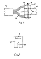
- FIG. 1 shows a cathode busbar 10 of one aluminium reduction cell and a cathode busbar 12 of an adjacent cell. It is not important which cell is downstream of the other.
- Mounted at the end of the cathode busbar 12 are two flexible aluminium conductors 14 whose ends are joined to aluminium blocks 16. These two blocks are mounted on either side of the cathode busbar 10 and held in position by means of a bolt 18 extending through a hole in the busbar and washers 20.
- the blocks 16 are electrically insulated from the busbar 10 by a tube 22 of insulating material surrounding the bolt and within the hole through the busbar; and by plates 24 of insulating material.
- the shape of the insulating plates 24 is shown in Figure 2. They include a slot 26 which fits over the bolt 18. When in position, the top end of the plate stands proud of the busbar 10 and is provided with a hole 28 constituting a handle by which it may easily and quickly be lifted out of position.
- the insulating plates 24 are in position, and insulate the busbars 10 and 12 from one another so that both associated cells are in commission.
- the current is switched off; the nut on the bolt 18 is loosened; the two insulating plates 24 are lifted out of position; the nut is re-tightened; and the current is switched on again.
- the insulators can be made of any material that is capable of withstanding the required pressure and other conditions; potential difference up to 150 V; temperatures up to 200-300°C. Suitable materials include 4 to 8 mm thick resin impregnated fibreglass tubes and plates.
- the invention provides the following advantages over the conventional shunting procedure:-
Landscapes
- Chemical & Material Sciences (AREA)
- Engineering & Computer Science (AREA)
- Chemical Kinetics & Catalysis (AREA)
- Electrochemistry (AREA)
- Materials Engineering (AREA)
- Metallurgy (AREA)
- Organic Chemistry (AREA)
- Electrolytic Production Of Metals (AREA)
Priority Applications (1)
| Application Number | Priority Date | Filing Date | Title |
|---|---|---|---|
| EP85304224A EP0205687A1 (fr) | 1985-06-13 | 1985-06-13 | Cellules de réduction pour l'aluminium |
Applications Claiming Priority (1)
| Application Number | Priority Date | Filing Date | Title |
|---|---|---|---|
| EP85304224A EP0205687A1 (fr) | 1985-06-13 | 1985-06-13 | Cellules de réduction pour l'aluminium |
Publications (1)
| Publication Number | Publication Date |
|---|---|
| EP0205687A1 true EP0205687A1 (fr) | 1986-12-30 |
Family
ID=8194260
Family Applications (1)
| Application Number | Title | Priority Date | Filing Date |
|---|---|---|---|
| EP85304224A Withdrawn EP0205687A1 (fr) | 1985-06-13 | 1985-06-13 | Cellules de réduction pour l'aluminium |
Country Status (1)
| Country | Link |
|---|---|
| EP (1) | EP0205687A1 (fr) |
Cited By (4)
| Publication number | Priority date | Publication date | Assignee | Title |
|---|---|---|---|---|
| WO1995034696A1 (fr) * | 1994-06-10 | 1995-12-21 | Jmt Engineering Pty. Ltd. | Connexion de cathode pour cuve d'electrolyse de l'aluminium |
| AU697337B2 (en) * | 1994-06-10 | 1998-10-01 | Jmt Engineering Pty Ltd | Cathode connection for aluminium smelter pot |
| RU2188259C1 (ru) * | 2001-02-02 | 2002-08-27 | Открытое акционерное общество "Сибирско-Уральская алюминиевая компания" | Узел шунтирования алюминиевого электролизера |
| GB2548571A (en) * | 2016-03-21 | 2017-09-27 | Dubai Aluminium Pjsc | Flexible electrical connector for electrolytic cell |
-
1985
- 1985-06-13 EP EP85304224A patent/EP0205687A1/fr not_active Withdrawn
Non-Patent Citations (4)
| Title |
|---|
| CHEMICAL ABSTRACTS, vol. 91, no. 22, November 1979, page 579, no. 184039c, Columbus, Ohio, US; & PL - A - 100 487 (HUTA ALUMINIUM) 15-02-1979 * |
| CHEMICAL ABSTRACTS, vol. 97, no. 4, October 1982, page 501, no. 117490d, Columbus, Ohio, US; & SU - A - 933 809 (BRATSK ALUMINUM PLANT) 07-06-1982 * |
| SOVIET INVENTIONS ILLUSTRATED, Section Chemical, week D18, 10th June 1981, abstract no. 32111 M28, Derwent Publications Ltd., London, GB; & SU - A - 757 606 (ALUM. MAGN. ELECTR. IND.) 23-08-1980 * |
| SOVIET INVENTIONS ILLUSTRATED, Section Chemical, week D44, 9th December 1981, abstract no. 81367 M28 X25, Derwent Publications Ltd., London, GB; & SU - A - 802 403 (PETROV E.V.) 09-02-1981 * |
Cited By (5)
| Publication number | Priority date | Publication date | Assignee | Title |
|---|---|---|---|---|
| WO1995034696A1 (fr) * | 1994-06-10 | 1995-12-21 | Jmt Engineering Pty. Ltd. | Connexion de cathode pour cuve d'electrolyse de l'aluminium |
| AU697337B2 (en) * | 1994-06-10 | 1998-10-01 | Jmt Engineering Pty Ltd | Cathode connection for aluminium smelter pot |
| US5855758A (en) * | 1994-06-10 | 1999-01-05 | Jmt Engineering Pty. Ltd. | Cathode connection for aluminium smelter pot and method |
| RU2188259C1 (ru) * | 2001-02-02 | 2002-08-27 | Открытое акционерное общество "Сибирско-Уральская алюминиевая компания" | Узел шунтирования алюминиевого электролизера |
| GB2548571A (en) * | 2016-03-21 | 2017-09-27 | Dubai Aluminium Pjsc | Flexible electrical connector for electrolytic cell |
Similar Documents
| Publication | Publication Date | Title |
|---|---|---|
| US9783900B2 (en) | Apparatus for use in electrorefining and electrowinning | |
| RU2481420C2 (ru) | Устройство и способ замыкания накоротко одного или более электролизеров в компоновке электролизеров, предназначенных для получения алюминия | |
| DE10392620T5 (de) | Brennstoffzellenstapel mit verbesserter Druckplatte und verbessertem Stromkollektor | |
| EP0097613B1 (fr) | Agencement de barres d'amenée de courant pour cellules d'electrolyse | |
| EP0205687A1 (fr) | Cellules de réduction pour l'aluminium | |
| US4227987A (en) | Means for connecting and disconnecting cells from circuit | |
| US3432422A (en) | Current conducting members for electrolytic cell | |
| KR830004457A (ko) | 횡렬식 고전류 전해셀에서 자기폭풍을 제거하기 위한 방법과 장치 | |
| CA1086259A (fr) | Circuit de cellules electrolytiques monopolaires | |
| CN211351259U (zh) | 一种智能变电站继电保护用配电柜接地装置 | |
| US3746817A (en) | Metal-enclosed switchgear | |
| CN208685075U (zh) | 一种铝电解系列头槽应急装置 | |
| CN220291471U (zh) | 一种汇流柜 | |
| EP3452640B1 (fr) | Équipement pour décuivrer un procédé d'électroraffinage et procédé de fonctionnement du procédé | |
| US20110006782A1 (en) | Insulation monitoring of servicing units used in a potroom for the production of aluminum by igneous electrolysis | |
| CA1261786A (fr) | Methode de court-circuitage electrique pour cellules electrolytiques | |
| WO2017064485A1 (fr) | Anode pour procédé d'extraction électrolytique de métal | |
| CN210379846U (zh) | 一种电器柜接线结构 | |
| CN201048243Y (zh) | 铠装移开式高压开关柜 | |
| CN108754541A (zh) | 一种铝电解系列头槽应急装置及其应急方法 | |
| US4285793A (en) | Slide-back type intercell bus bar connector | |
| CN209016467U (zh) | 一种开关柜 | |
| DE102024104606B3 (de) | Leistungsversorgung, die eine manuelle wartungstrennvorrichtung (msd) mit einer pyro-sicherung enthält | |
| CN220156174U (zh) | 一种便于固定线缆的母线槽 | |
| CN114555867B (zh) | 包括短接装置和断路器的电解槽供电电路 |
Legal Events
| Date | Code | Title | Description |
|---|---|---|---|
| PUAI | Public reference made under article 153(3) epc to a published international application that has entered the european phase |
Free format text: ORIGINAL CODE: 0009012 |
|
| AK | Designated contracting states |
Kind code of ref document: A1 Designated state(s): DE FR |
|
| 17P | Request for examination filed |
Effective date: 19870610 |
|
| 17Q | First examination report despatched |
Effective date: 19880601 |
|
| STAA | Information on the status of an ep patent application or granted ep patent |
Free format text: STATUS: THE APPLICATION IS DEEMED TO BE WITHDRAWN |
|
| 18D | Application deemed to be withdrawn |
Effective date: 19881019 |
|
| RIN1 | Information on inventor provided before grant (corrected) |
Inventor name: SHANKLAND, WILLIAM Inventor name: LABLANS, JOHANNES FRANCISCUS |