EP0205806A1 - Procédé et circuit de commande d'une soupape - Google Patents
Procédé et circuit de commande d'une soupape Download PDFInfo
- Publication number
- EP0205806A1 EP0205806A1 EP86105473A EP86105473A EP0205806A1 EP 0205806 A1 EP0205806 A1 EP 0205806A1 EP 86105473 A EP86105473 A EP 86105473A EP 86105473 A EP86105473 A EP 86105473A EP 0205806 A1 EP0205806 A1 EP 0205806A1
- Authority
- EP
- European Patent Office
- Prior art keywords
- current
- transistor
- thyristor
- circuit according
- circuit
- Prior art date
- Legal status (The legal status is an assumption and is not a legal conclusion. Google has not performed a legal analysis and makes no representation as to the accuracy of the status listed.)
- Granted
Links
- 238000000034 method Methods 0.000 title claims 2
- 238000002485 combustion reaction Methods 0.000 claims description 6
- 230000005284 excitation Effects 0.000 claims description 2
- 230000000903 blocking effect Effects 0.000 description 5
- 239000004065 semiconductor Substances 0.000 description 4
- 230000007423 decrease Effects 0.000 description 3
- 238000010586 diagram Methods 0.000 description 3
- 238000011144 upstream manufacturing Methods 0.000 description 2
- XUIMIQQOPSSXEZ-UHFFFAOYSA-N Silicon Chemical compound [Si] XUIMIQQOPSSXEZ-UHFFFAOYSA-N 0.000 description 1
- 230000004913 activation Effects 0.000 description 1
- 238000010276 construction Methods 0.000 description 1
- 230000000694 effects Effects 0.000 description 1
- 238000005265 energy consumption Methods 0.000 description 1
- 238000010304 firing Methods 0.000 description 1
- 238000010438 heat treatment Methods 0.000 description 1
- 229910052710 silicon Inorganic materials 0.000 description 1
- 239000010703 silicon Substances 0.000 description 1
Images


Classifications
-
- F—MECHANICAL ENGINEERING; LIGHTING; HEATING; WEAPONS; BLASTING
- F02—COMBUSTION ENGINES; HOT-GAS OR COMBUSTION-PRODUCT ENGINE PLANTS
- F02D—CONTROLLING COMBUSTION ENGINES
- F02D41/00—Electrical control of supply of combustible mixture or its constituents
- F02D41/20—Output circuits, e.g. for controlling currents in command coils
-
- F—MECHANICAL ENGINEERING; LIGHTING; HEATING; WEAPONS; BLASTING
- F01—MACHINES OR ENGINES IN GENERAL; ENGINE PLANTS IN GENERAL; STEAM ENGINES
- F01L—CYCLICALLY OPERATING VALVES FOR MACHINES OR ENGINES
- F01L9/00—Valve-gear or valve arrangements actuated non-mechanically
- F01L9/20—Valve-gear or valve arrangements actuated non-mechanically by electric means
-
- H—ELECTRICITY
- H01—ELECTRIC ELEMENTS
- H01F—MAGNETS; INDUCTANCES; TRANSFORMERS; SELECTION OF MATERIALS FOR THEIR MAGNETIC PROPERTIES
- H01F7/00—Magnets
- H01F7/06—Electromagnets; Actuators including electromagnets
- H01F7/08—Electromagnets; Actuators including electromagnets with armatures
- H01F7/18—Circuit arrangements for obtaining desired operating characteristics, e.g. for slow operation, for sequential energisation of windings, for high-speed energisation of windings
- H01F7/1805—Circuit arrangements for holding the operation of electromagnets or for holding the armature in attracted position with reduced energising current
-
- F—MECHANICAL ENGINEERING; LIGHTING; HEATING; WEAPONS; BLASTING
- F02—COMBUSTION ENGINES; HOT-GAS OR COMBUSTION-PRODUCT ENGINE PLANTS
- F02D—CONTROLLING COMBUSTION ENGINES
- F02D41/00—Electrical control of supply of combustible mixture or its constituents
- F02D41/0002—Controlling intake air
- F02D2041/001—Controlling intake air for engines with variable valve actuation
Definitions
- the invention relates to an internal combustion engine with gas exchange valves according to the preamble of claim 1.
- the object of the invention is to provide a generic internal combustion engine in which the energy consumption is reduced by the current applied to the electromagnets.
- the current switching element is also designed as a semiconductor, specifically as a thyristor.
- the thyristor can be opened by a control command, but can only be switched into its blocking state if the current flowing through the thyristor is briefly drawn off, so that the thyristor is extinguished.
- the invention makes use of the knowledge that a transistor gate can withstand a much higher current than the current which it can switch in continuous operation without damage when subjected to a short-term load.
- the inrush current for the electromagnetic consumer is supplied via the thyristor, but for switching off it is necessary for a few milliseconds to clear the thyristor the entire current is taken over by the transistor, which can cope with this brief surge.
- the subsequent clocking at a current that is only about 10 to 20% of the inrush current can be done solely via the transistor, which is thereby dimensioned lower.
- the transistor's collector-emitter saturation voltage is usually lower than the thyristor, such an increase in the resistance of the thyristor branch is not absolutely necessary.
- an ohmic resistor is provided for safety, its resistance value can be on the order of ⁇ 1 ohm.
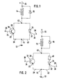
- the transistor 18 can only withstand a current which corresponds approximately to the holding current (taking into account a safety tolerance), but is not destroyed by a short-term, much stronger peak current. Accordingly, a relatively inexpensive type can be used as transistor 18, which would not be able to control the entire inrush current by its design.
- the current through thyristor 34 has dropped to a value which corresponds approximately to the holding current.
- the base 24 of the transistor 18 is now supplied with a signal, shown in FIG. 4b, which opens the collector-emitter path of the transistor 18 and thus enables a current to flow through the electromagnetic consumer 14.
- transistor 18 opens at time T3 the current flows through transistor 18, thyristor 34 is de-energized and thus changes to its blocking state. This now also results in a holding current I halt , the magnitude of which is formed by the pulse duty factor, similar to the illustration in FIG. 3c.
Landscapes
- Engineering & Computer Science (AREA)
- Physics & Mathematics (AREA)
- Electromagnetism (AREA)
- Mechanical Engineering (AREA)
- General Engineering & Computer Science (AREA)
- Power Engineering (AREA)
- Chemical & Material Sciences (AREA)
- Combustion & Propulsion (AREA)
- Valve Device For Special Equipments (AREA)
- Emergency Protection Circuit Devices (AREA)
- Magnetically Actuated Valves (AREA)
- Electrical Control Of Air Or Fuel Supplied To Internal-Combustion Engine (AREA)
Applications Claiming Priority (2)
| Application Number | Priority Date | Filing Date | Title |
|---|---|---|---|
| DE3515041 | 1985-04-25 | ||
| DE3515041 | 1985-04-25 |
Publications (2)
| Publication Number | Publication Date |
|---|---|
| EP0205806A1 true EP0205806A1 (fr) | 1986-12-30 |
| EP0205806B1 EP0205806B1 (fr) | 1989-10-25 |
Family
ID=6269147
Family Applications (1)
| Application Number | Title | Priority Date | Filing Date |
|---|---|---|---|
| EP86105473A Expired EP0205806B1 (fr) | 1985-04-25 | 1986-04-21 | Procédé et circuit de commande d'une soupape |
Country Status (5)
| Country | Link |
|---|---|
| US (1) | US4885658A (fr) |
| EP (1) | EP0205806B1 (fr) |
| JP (1) | JPH0666187B2 (fr) |
| DE (1) | DE3666647D1 (fr) |
| ES (1) | ES8703214A1 (fr) |
Families Citing this family (10)
| Publication number | Priority date | Publication date | Assignee | Title |
|---|---|---|---|---|
| US5159522A (en) * | 1990-02-27 | 1992-10-27 | Dana Corporation | Electric clutch actuator |
| DE4414609B4 (de) * | 1994-04-27 | 2005-12-22 | Robert Bosch Gmbh | Einrichtung zur Ansteuerung eines Verbrauchers |
| DE4434684A1 (de) * | 1994-09-28 | 1996-04-04 | Fev Motorentech Gmbh & Co Kg | Verfahren zur Steuerung der Ankerbewegung einer elektromagnetischen Schaltanordnung |
| JP3134724B2 (ja) * | 1995-02-15 | 2001-02-13 | トヨタ自動車株式会社 | 内燃機関の弁駆動装置 |
| GB2300306B (en) * | 1995-04-25 | 2000-02-09 | Pectel Control Systems Ltd | Fluid injector systems |
| JP3828239B2 (ja) * | 1997-05-22 | 2006-10-04 | 三菱電機株式会社 | 燃料噴射用インジェクタの制御装置 |
| US5910890A (en) * | 1998-02-12 | 1999-06-08 | Eaton Corporation | Circuit for controlling application of electricity to a coil of and electric current switching apparatus |
| US6631067B2 (en) | 2001-12-28 | 2003-10-07 | Visteon Global Technologies, Inc. | Electromagnetic actuator for engine valves |
| KR101659715B1 (ko) * | 2009-06-18 | 2016-09-26 | 코닌클리케 필립스 엔.브이. | Triac 디머를 위한 led들을 갖는 파워 인터페이스 |
| EP2461342B1 (fr) * | 2010-12-06 | 2015-01-28 | Siemens Aktiengesellschaft | Module de commutation protégé contre les erreurs |
Citations (6)
| Publication number | Priority date | Publication date | Assignee | Title |
|---|---|---|---|---|
| US3439189A (en) * | 1965-12-28 | 1969-04-15 | Teletype Corp | Gated switching circuit comprising parallel combination of latching and shunt switches series-connected with input-output control means |
| US3549955A (en) * | 1969-08-19 | 1970-12-22 | T O Paine | Drive circuit for minimizing power consumption in inductive load |
| FR2053898A5 (fr) * | 1969-04-25 | 1971-04-16 | Rca Corp | |
| DE2402083A1 (de) * | 1974-01-17 | 1975-07-31 | Boge Kompressoren Otto Boge | Steuerungsvorrichtung fuer magnetventile, insbesondere an verdichteranlagen |
| DE3024109A1 (de) * | 1980-06-27 | 1982-01-21 | Pischinger, Franz, Prof. Dipl.-Ing. Dr.Techn., 5100 Aachen | Elektromagnetisch arbeitende stelleinrichtung |
| DE3328309A1 (de) * | 1983-08-05 | 1985-02-14 | Papst-Motoren GmbH & Co KG, 7742 St Georgen | Ansprechschaltung fuer elektromagnete |
Family Cites Families (3)
| Publication number | Priority date | Publication date | Assignee | Title |
|---|---|---|---|---|
| JPS609024A (ja) * | 1983-06-29 | 1985-01-18 | 富士電機株式会社 | 電磁石装置のコイル駆動回路 |
| DE3515039C2 (de) * | 1985-04-25 | 1987-04-02 | Klöckner, Wolfgang, Dr., 8033 Krailling | Schaltung für ein elektromagnetisch betätigtes Gaswechselventil einer Brennkraftmaschine |
| DE3611221A1 (de) * | 1985-04-25 | 1986-11-06 | Klöckner, Wolfgang, Dr., 8033 Krailling | Brennkraftmaschine mit gaswechselventilen |
-
1986
- 1986-04-10 ES ES553844A patent/ES8703214A1/es not_active Expired
- 1986-04-21 DE DE8686105473T patent/DE3666647D1/de not_active Expired
- 1986-04-21 JP JP61091972A patent/JPH0666187B2/ja not_active Expired - Fee Related
- 1986-04-21 EP EP86105473A patent/EP0205806B1/fr not_active Expired
-
1987
- 1987-11-23 US US07/124,490 patent/US4885658A/en not_active Expired - Lifetime
Patent Citations (6)
| Publication number | Priority date | Publication date | Assignee | Title |
|---|---|---|---|---|
| US3439189A (en) * | 1965-12-28 | 1969-04-15 | Teletype Corp | Gated switching circuit comprising parallel combination of latching and shunt switches series-connected with input-output control means |
| FR2053898A5 (fr) * | 1969-04-25 | 1971-04-16 | Rca Corp | |
| US3549955A (en) * | 1969-08-19 | 1970-12-22 | T O Paine | Drive circuit for minimizing power consumption in inductive load |
| DE2402083A1 (de) * | 1974-01-17 | 1975-07-31 | Boge Kompressoren Otto Boge | Steuerungsvorrichtung fuer magnetventile, insbesondere an verdichteranlagen |
| DE3024109A1 (de) * | 1980-06-27 | 1982-01-21 | Pischinger, Franz, Prof. Dipl.-Ing. Dr.Techn., 5100 Aachen | Elektromagnetisch arbeitende stelleinrichtung |
| DE3328309A1 (de) * | 1983-08-05 | 1985-02-14 | Papst-Motoren GmbH & Co KG, 7742 St Georgen | Ansprechschaltung fuer elektromagnete |
Also Published As
| Publication number | Publication date |
|---|---|
| DE3666647D1 (en) | 1989-11-30 |
| ES553844A0 (es) | 1987-02-16 |
| US4885658A (en) | 1989-12-05 |
| ES8703214A1 (es) | 1987-02-16 |
| JPH0666187B2 (ja) | 1994-08-24 |
| EP0205806B1 (fr) | 1989-10-25 |
| JPS61248506A (ja) | 1986-11-05 |
Similar Documents
| Publication | Publication Date | Title |
|---|---|---|
| EP0203354B1 (fr) | Procédé et circuit de commande d'une soupape | |
| EP0704097B1 (fr) | Procede et dispositif de commande de consommateurs electromagnetiques | |
| DE2828678C2 (fr) | ||
| EP0006843B2 (fr) | Valve électromagnétique avec commande électronique | |
| WO1987005075A1 (fr) | Procede et circuit d'excitation de consommateurs electromagnetiques | |
| DE19963154B4 (de) | Verfahren zur Vorgabe des Stroms durch ein induktives Bauteil | |
| DE60124760T2 (de) | Hybride elektrische schalteinrichtung | |
| EP0205806B1 (fr) | Procédé et circuit de commande d'une soupape | |
| DE2050219A1 (de) | Einrichtung zur Steuerung eines Elektromagneten | |
| DE2018551A1 (de) | Leistungsschaltsystem zur Erzeu gung eines Leistungssignals | |
| DE102007001414B3 (de) | Schaltungsanordnung sowie Verfahren zum Betrieb einer induktiven Last | |
| EP0650177B1 (fr) | Méthode pour commander des relais arrangés en parallèle | |
| DE3611221A1 (de) | Brennkraftmaschine mit gaswechselventilen | |
| DE2447199A1 (de) | Schaltungsanordnung zur steuerung eines relais | |
| EP0829123B1 (fr) | Circuit de roue libre a duree de temporisation d'arret reglable | |
| DE3231083A1 (de) | Schaltung zur automatischen verringerung der einer last zugefuehrten leistung | |
| DE2347714A1 (de) | Steuersystem zur sequentiellen betaetigung mehrerer energieverbrauchender lasten | |
| BE1026605B1 (de) | Relaismodul | |
| DE19725317B4 (de) | Schaltungsanordnung zur Ansteuerung eines mit Gleichspannung betätigbaren Magnetventiles | |
| DE2016198A1 (de) | Schaltungsanordnung zur Steuerung von elektrischen Schrittmotoren bzw Schritt magnetanordnungen | |
| DE102018122269A1 (de) | Relaismodul | |
| DE2402083A1 (de) | Steuerungsvorrichtung fuer magnetventile, insbesondere an verdichteranlagen | |
| DE102024205717A1 (de) | Treiber zum ansteuern einer elektromechanischen vorrichtung | |
| DE2854587A1 (de) | Steuerschaltung fuer einen kontaktgeber | |
| DE4307835A1 (de) | Schaltungsanordnung zur zeitgenauen Betätigung eines Schaltmagneten in einer Kraftstoff-Einspritzvorrichtung |
Legal Events
| Date | Code | Title | Description |
|---|---|---|---|
| PUAI | Public reference made under article 153(3) epc to a published international application that has entered the european phase |
Free format text: ORIGINAL CODE: 0009012 |
|
| AK | Designated contracting states |
Kind code of ref document: A1 Designated state(s): DE FR GB IT SE |
|
| 17P | Request for examination filed |
Effective date: 19870212 |
|
| 17Q | First examination report despatched |
Effective date: 19890404 |
|
| ITF | It: translation for a ep patent filed | ||
| GRAA | (expected) grant |
Free format text: ORIGINAL CODE: 0009210 |
|
| AK | Designated contracting states |
Kind code of ref document: B1 Designated state(s): DE FR GB IT SE |
|
| GBT | Gb: translation of ep patent filed (gb section 77(6)(a)/1977) | ||
| REF | Corresponds to: |
Ref document number: 3666647 Country of ref document: DE Date of ref document: 19891130 |
|
| ET | Fr: translation filed | ||
| ITPR | It: changes in ownership of a european patent |
Owner name: CESSIONE;AUDI AG |
|
| REG | Reference to a national code |
Ref country code: GB Ref legal event code: 732 |
|
| PLBE | No opposition filed within time limit |
Free format text: ORIGINAL CODE: 0009261 |
|
| STAA | Information on the status of an ep patent application or granted ep patent |
Free format text: STATUS: NO OPPOSITION FILED WITHIN TIME LIMIT |
|
| 26N | No opposition filed | ||
| REG | Reference to a national code |
Ref country code: FR Ref legal event code: TP |
|
| ITTA | It: last paid annual fee | ||
| EAL | Se: european patent in force in sweden |
Ref document number: 86105473.2 |
|
| REG | Reference to a national code |
Ref country code: GB Ref legal event code: IF02 |
|
| PGFP | Annual fee paid to national office [announced via postgrant information from national office to epo] |
Ref country code: GB Payment date: 20030325 Year of fee payment: 18 |
|
| PGFP | Annual fee paid to national office [announced via postgrant information from national office to epo] |
Ref country code: DE Payment date: 20030405 Year of fee payment: 18 |
|
| PGFP | Annual fee paid to national office [announced via postgrant information from national office to epo] |
Ref country code: SE Payment date: 20030417 Year of fee payment: 18 Ref country code: FR Payment date: 20030417 Year of fee payment: 18 |
|
| PG25 | Lapsed in a contracting state [announced via postgrant information from national office to epo] |
Ref country code: GB Free format text: LAPSE BECAUSE OF NON-PAYMENT OF DUE FEES Effective date: 20040421 |
|
| PG25 | Lapsed in a contracting state [announced via postgrant information from national office to epo] |
Ref country code: SE Free format text: LAPSE BECAUSE OF NON-PAYMENT OF DUE FEES Effective date: 20040422 |
|
| PG25 | Lapsed in a contracting state [announced via postgrant information from national office to epo] |
Ref country code: DE Free format text: LAPSE BECAUSE OF NON-PAYMENT OF DUE FEES Effective date: 20041103 |
|
| EUG | Se: european patent has lapsed | ||
| GBPC | Gb: european patent ceased through non-payment of renewal fee |
Effective date: 20040421 |
|
| PG25 | Lapsed in a contracting state [announced via postgrant information from national office to epo] |
Ref country code: FR Free format text: LAPSE BECAUSE OF NON-PAYMENT OF DUE FEES Effective date: 20041231 |
|
| REG | Reference to a national code |
Ref country code: FR Ref legal event code: ST |
|
| PG25 | Lapsed in a contracting state [announced via postgrant information from national office to epo] |
Ref country code: IT Free format text: LAPSE BECAUSE OF NON-PAYMENT OF DUE FEES;WARNING: LAPSES OF ITALIAN PATENTS WITH EFFECTIVE DATE BEFORE 2007 MAY HAVE OCCURRED AT ANY TIME BEFORE 2007. THE CORRECT EFFECTIVE DATE MAY BE DIFFERENT FROM THE ONE RECORDED. Effective date: 20050421 |