EP0205918A1 - Jauge avec réglage de la pression du palpeur - Google Patents
Jauge avec réglage de la pression du palpeur Download PDFInfo
- Publication number
- EP0205918A1 EP0205918A1 EP86106823A EP86106823A EP0205918A1 EP 0205918 A1 EP0205918 A1 EP 0205918A1 EP 86106823 A EP86106823 A EP 86106823A EP 86106823 A EP86106823 A EP 86106823A EP 0205918 A1 EP0205918 A1 EP 0205918A1
- Authority
- EP
- European Patent Office
- Prior art keywords
- movable member
- probe
- stylus
- improvement
- spring
- Prior art date
- Legal status (The legal status is an assumption and is not a legal conclusion. Google has not performed a legal analysis and makes no representation as to the accuracy of the status listed.)
- Granted
Links
- 239000000523 sample Substances 0.000 title claims abstract description 57
- 241001422033 Thestylus Species 0.000 claims abstract description 30
- 235000014676 Phragmites communis Nutrition 0.000 claims description 9
- 230000003247 decreasing effect Effects 0.000 claims description 2
- 238000010276 construction Methods 0.000 description 9
- 238000000034 method Methods 0.000 description 6
- 230000003287 optical effect Effects 0.000 description 5
- 230000008901 benefit Effects 0.000 description 3
- 238000003754 machining Methods 0.000 description 3
- 239000000853 adhesive Substances 0.000 description 2
- 230000001070 adhesive effect Effects 0.000 description 2
- 238000013459 approach Methods 0.000 description 2
- 238000005520 cutting process Methods 0.000 description 2
- 238000004519 manufacturing process Methods 0.000 description 2
- 230000008054 signal transmission Effects 0.000 description 2
- 230000005540 biological transmission Effects 0.000 description 1
- 230000006835 compression Effects 0.000 description 1
- 238000007906 compression Methods 0.000 description 1
- 239000000356 contaminant Substances 0.000 description 1
- 238000005553 drilling Methods 0.000 description 1
- 230000007613 environmental effect Effects 0.000 description 1
- 238000012986 modification Methods 0.000 description 1
- 230000004048 modification Effects 0.000 description 1
- 230000002093 peripheral effect Effects 0.000 description 1
- 230000002040 relaxant effect Effects 0.000 description 1
Images
Classifications
-
- G—PHYSICS
- G01—MEASURING; TESTING
- G01M—TESTING STATIC OR DYNAMIC BALANCE OF MACHINES OR STRUCTURES; TESTING OF STRUCTURES OR APPARATUS, NOT OTHERWISE PROVIDED FOR
- G01M1/00—Testing static or dynamic balance of machines or structures
-
- G—PHYSICS
- G01—MEASURING; TESTING
- G01B—MEASURING LENGTH, THICKNESS OR SIMILAR LINEAR DIMENSIONS; MEASURING ANGLES; MEASURING AREAS; MEASURING IRREGULARITIES OF SURFACES OR CONTOURS
- G01B7/00—Measuring arrangements characterised by the use of electric or magnetic techniques
- G01B7/002—Constructional details of contacts for gauges actuating one or more contacts
-
- G—PHYSICS
- G01—MEASURING; TESTING
- G01B—MEASURING LENGTH, THICKNESS OR SIMILAR LINEAR DIMENSIONS; MEASURING ANGLES; MEASURING AREAS; MEASURING IRREGULARITIES OF SURFACES OR CONTOURS
- G01B7/00—Measuring arrangements characterised by the use of electric or magnetic techniques
- G01B7/004—Measuring arrangements characterised by the use of electric or magnetic techniques for measuring coordinates of points
- G01B7/008—Measuring arrangements characterised by the use of electric or magnetic techniques for measuring coordinates of points using coordinate measuring machines
- G01B7/012—Contact-making feeler heads therefor
Definitions
- This invention relates to measuring devices and, more particularly, to probes having a movable stylus for detecting contact with an object.
- a probe is a type of transducer which includes a movable stylus for detecting contact with an object. Some probes provide an output proportional to stylus deflection while others simply make or break an electrical circuit when the stylus moves from its rest position upon contact with an object. The latter type of probes are generally referred to as touch probes.
- U.S. Patent No. 4,451,987 to Cusack discloses an example of a touch probe.
- probe constructions often consist of a switch head that is either directly connected to an adapter or to an intermediate probe body containing signal transmission electronic circuitry, which, in tum, is connected to the adapter.
- the ad- apater is designed so that the probe can be used in the machine tool spindle in the same manner as the cutting tools.
- the probe body is often designed so that it can be inserted into slots in a turret or the like so that the probe can be likewise mounted in the same manner as other tools used in the machine.
- the switch head of a probe generally consists of a movable member having a first set of contacts thereon that oppose a second set of .fixed contacts.
- Some type of biasing arrangement is applied to the movable member for urging it toward the fixed contacts to maintain the first and second set of contacts in engagement when the stylus is in a rest position.
- the spring pressure within the probe causes the stylus to sit in a unique rest position and returns the stylus to this position following each deflection. It sometimes becomes necessary to adjust the spring pressure on the movable member in special circumstances, for example, when excessive machine vibration causes spurious readings or when the weight of the stylus is too great to be supported by the standard pressure.
- this technique compresses or relaxes the spring, depending upon the relative spacing between the switch head and a fixed annular receptacle on the probe body which are threadably coupled together.
- the Renishaw Model TP-4 probe also apparently uses some type of external rotatable ring construction on the probe to adjust spring pressure.
- the present invention provides a simple, yet reliable method of adjusting stylus spring pressure.
- the movable member is provided with a bore to wnich the stylus is removably connected.
- the bore extends into the interior of the probe housing and provides access to the biasing means for adjusting the pressure on the movable member when the stylus is removed.
- the movable member is generally T-shaped in cross section including a plate carrying a first set of contacts and a perpendicularly extending shaft portion having a threaded bore therein.
- the stylus is threaded to one end of the bore.
- an axially adjusted member such as a set screw, which contacts a portion of the spring.
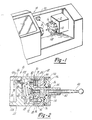
- FIGURE 1 is an environmental view showing an example of a probe 10 which may benefit from the teachings of the present invention.
- Probe 10 is mounted in a turret 12 of a computer numerally controlled machining center 14.
- Probe 10 is mounted in turret 12 in the same manner as cutting tools 16 that are used to' perform machining operations on a workpiece (not shown) held in a chuck 18.
- probe 10 may form part of a telemetry system employing an optical transmitter/receiver box 20.
- This type of system is commercially available from the Assignee of the present invention and is known as the "Touch Probe Telemetry" system. The general operation of such a system is described in U.S. Patent No.
- probe 10 is battery operated and is switched on from an optical signal from box 20.
- the probe 10 transmits an optical signal back to box 20 which is coupled through an interface to the machine controller.
- the machine controller can calculate information about the workpiece since it is designed to know the position of the stylus at all times during its movement and will record the positioned data of the stylus when it receives the signal indicating that the stylus has contacted the workpiece.
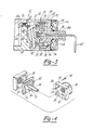
- the probe 10 of the preferred embodiment is shown in more detail in FIGURES 2-4.
- the probe 10 employs a housing 22 whose rearward end or body contains the battery 24 and electronic circuitry 26 for performing the functions noted above. Since the present invention primarily concerns the switch head 28 construction, they are shown only - schematically in the drawings. To some extent, the switch head 28 resembles that disclosed in the '987 Cusack patent noted above, which is also hereby incorporated by reference. Consequently, focus will be made on the novel aspects of this invention and the reader may refer to the referenced patents for background information.
- Switch head 28 employs a movable member - (generally designated by the numeral 30) which is generally T-shaped in cross-sectional dimension.
- Movable member 30 consists of a generally triangular shaped (when viewed from the left of FIGURE 2) pivot piate 32 and a perpendicularly connected nose or shaft portion 34.
- the movable member 30 includes a threaded bore 36 therein which passes through the shaft 34 and pivot plate 32 portions to thereby permit access to the interior of the probe containing biasing spring 38.
- a stylus 40 is threaded into one end of bore 36 and held in place by a suitable locknut 42.
- the user When it is desired to adjust the spring pressure on the movable member, the user simply unscrews the stylus 40 from the movable member and inserts a suitable tool through the bore 36 to adjust the spring pressure on the movable member. It is contemplated that different adjustment schemes can be used since an equally wide variety of biasing spring construction can likewise be used.
- biasing spring 38 takes the form of a taper spring having a plurality of loops of decreasing diameter.
- the largest spring loop is abutted against a fixed stop 44.
- the smallest spring loop is received in an annular groove 46 in an inner face of a cap 48.
- the outer cap face 50 is in the form of a conical depression which subtends a given angle and the middle of the cap includes a small hole therein.
- a set screw 52 is threaded into the internal end of bore 36 and serves as an axially adjustable member.
- Set screw 52 has a conical end 54 subtending an angle less than the angle defined by face 50 of cap 48. The purpose of the respective angular dimensions is to provide an easy way of centering the respective components.
- FIGURE 3 illustrates the method of adjusting the spring pressure according to the preferred embodiment.
- Stylus 40 is unscrewed from shaft 34 and the user inserts an Allen wrench 60 or the like into the socket 62 provided on the opposite end of set screw 52.
- the user rotates the set screw 52 so it moves leftwardly (as viewed in the drawings) so as to compress spring 38.
- the additional compression on spring 38 applies more force to movable member 30 to hold it in its rest position with more pressure.
- moving set screw 52 to the right relaxes the spring pressure on the movable member. Once the adjustment is completed, the stylus can be reinserted.
- the contact arrangement and the way in which electrical connection is made thereto is the contact arrangement and the way in which electrical connection is made thereto.
- the reed spring 70 which keeps the movable member 30 centered, also serves as part of the electrical connection path .to the contacts.
- Reed spring 70 includes a peripheral frame 72 which is clamped to the conductive housing 22 by way of a series of screws 74.
- a web portion 76 of the reed spring is mechanically and electrically connected to the conductive movable member 30.
- this is accomplished by way of a rectangular block 76 which clamps the upper portion of spring web 76 against an upper portion of pivot plate 32 by way of suitable fasteners 80.
- a continuous rectangular pad 82 is mounted to block 78 but is insulated therefrom by way of suitable nonconductive adhesive 84.
- a smaller electrically conductive pad 86 is mechanically and electrically connected to a lower apex of the pivot plate 32 by way of a suitable standoff 88.
- Opposing the rectangular pad 82 and circular pad 86 are three individual conductive balls 90, 92 and 94. Each of these balls are affixed to the probe housing and insulated therefrom.
- Balls 92 and 94 are electrically connected together by way of a wire 98 having an insulating jacket.
- a similar wire 100 is connected to ball 90, passes through the interior of the switch head, through a hole 102 in wall 104 and is finally connected to the electronic circuitry 26.
- circuitry 26 and battery 24 are located within a compartment 104 in the rear of probe housing 22, the compartment being enclosed by a lid 106.
- the electrical path is thus established as tol- lows: the negative side of battery 24 and reed spring 72 is connected to conductive probe housing 22 which serves as an electrical ground.
- reed spring 72 When the stylus is in its rest position (i.e. not deflected), a closed ciruit is provided via reed spring 72 to disc pad 86 which rests on ball 94.
- Ball 94 is connected via wire 98 to ball 92.
- Ball 92 is engaged by one side of rectangular block pad 82 which is conductive throughout its length so that it serves as an electrical path to ball 90 upon which the other side of pad 82 rests.
- Ball 90 is connected to the electronic circuitry 26 via wire 100.
- the electrical circuitry 26 is connected to the post--. tive end of battery 24 to complete the circuit.
- circuitry 26 which, in the preferred embodiment, generates an infrared optical signal via diode 108 (FIGURE 1) to the box 70.
- suitable means are provided for protecting the internal components of the probe from debris and other contaminants. This is accomplished in this embodiment by way of a flexible diaphragm 110 and a movable shield member 112 resiliently held in place by spring 114. Shield 112 is thus capable of moving with the stylus relative to the outer fixed end 116 of the probe housing.
Landscapes
- Physics & Mathematics (AREA)
- General Physics & Mathematics (AREA)
- Length Measuring Devices With Unspecified Measuring Means (AREA)
- Measurement Of Length, Angles, Or The Like Using Electric Or Magnetic Means (AREA)
- A Measuring Device Byusing Mechanical Method (AREA)
- Testing Or Measuring Of Semiconductors Or The Like (AREA)
- Measuring Leads Or Probes (AREA)
Priority Applications (1)
| Application Number | Priority Date | Filing Date | Title |
|---|---|---|---|
| AT86106823T ATE47752T1 (de) | 1985-06-17 | 1986-05-20 | Sonde mit taststiftdruckregelung. |
Applications Claiming Priority (2)
| Application Number | Priority Date | Filing Date | Title |
|---|---|---|---|
| US06/745,863 US4625417A (en) | 1985-06-17 | 1985-06-17 | Probe with stylus pressure adjustment |
| US745863 | 1985-06-17 |
Publications (2)
| Publication Number | Publication Date |
|---|---|
| EP0205918A1 true EP0205918A1 (fr) | 1986-12-30 |
| EP0205918B1 EP0205918B1 (fr) | 1989-11-02 |
Family
ID=24998555
Family Applications (1)
| Application Number | Title | Priority Date | Filing Date |
|---|---|---|---|
| EP86106823A Expired EP0205918B1 (fr) | 1985-06-17 | 1986-05-20 | Jauge avec réglage de la pression du palpeur |
Country Status (7)
| Country | Link |
|---|---|
| US (1) | US4625417A (fr) |
| EP (1) | EP0205918B1 (fr) |
| JP (1) | JPS61292501A (fr) |
| KR (1) | KR900003750B1 (fr) |
| AT (1) | ATE47752T1 (fr) |
| CA (1) | CA1251272A (fr) |
| DE (1) | DE3666731D1 (fr) |
Cited By (3)
| Publication number | Priority date | Publication date | Assignee | Title |
|---|---|---|---|---|
| EP0388993A1 (fr) * | 1986-04-24 | 1990-09-26 | Renishaw plc | Capteur pour mesurer des pièces en cours d'usinage |
| EP0418992A3 (fr) * | 1989-09-20 | 1991-04-03 | Adalbert Dr. Obal | Tonomètre à impression |
| US5212872A (en) * | 1989-03-31 | 1993-05-25 | Reinshaw Plc | Touch probe |
Families Citing this family (16)
| Publication number | Priority date | Publication date | Assignee | Title |
|---|---|---|---|---|
| US4786769A (en) * | 1985-03-06 | 1988-11-22 | Process Equipment Company | Safety coupling device for robotic tooling |
| DE3640160A1 (de) * | 1986-11-25 | 1988-06-01 | Heidenhain Gmbh Dr Johannes | Mehrkoordinaten-tastkopf |
| DE3811235A1 (de) * | 1987-08-21 | 1989-10-19 | Wegu Messtechnik | Dynamischer tastkopf |
| DE3842151A1 (de) * | 1988-12-15 | 1990-06-21 | Zeiss Carl Fa | Tastkopf vom schaltenden typ |
| US5247751A (en) * | 1990-09-29 | 1993-09-28 | Nikon Corporation | Touch probe |
| EP0524341B1 (fr) * | 1991-07-26 | 1994-09-14 | Dr. Johannes Heidenhain GmbH | Tête de palpage pour coordonnées multiples |
| JP3153111B2 (ja) * | 1995-09-18 | 2001-04-03 | 株式会社ミツトヨ | 手動操作型三次元測定機 |
| JP3267116B2 (ja) * | 1995-09-19 | 2002-03-18 | ミノルタ株式会社 | 接触式センサおよび移動体 |
| US6009597A (en) * | 1998-05-11 | 2000-01-04 | Yu; King-Sung | Buffer device of door |
| GB9907643D0 (en) * | 1999-04-06 | 1999-05-26 | Renishaw Plc | Measuring probe |
| DE19937204C1 (de) * | 1999-07-08 | 2001-02-01 | Mahr Gmbh | Messtaster |
| WO2002063235A2 (fr) * | 2001-02-02 | 2002-08-15 | Renishaw Plc | Sonde pour machine-outil |
| GB0608998D0 (en) * | 2006-05-08 | 2006-06-14 | Renishaw Plc | Contact sensing probe |
| CN100478643C (zh) * | 2007-04-26 | 2009-04-15 | 武汉理工大学 | 探测物体和孔隙的传感器 |
| EP2028439A1 (fr) * | 2007-07-26 | 2009-02-25 | Renishaw plc | Appareil de mesure pouvant être désactivé |
| JP2009125853A (ja) * | 2007-11-22 | 2009-06-11 | Murata Mach Ltd | センサ |
Citations (3)
| Publication number | Priority date | Publication date | Assignee | Title |
|---|---|---|---|---|
| GB2049198A (en) * | 1979-05-01 | 1980-12-17 | Renishaw Electrical Ltd | Probe for use in measuring apparatus |
| DE3317299A1 (de) * | 1982-05-11 | 1983-11-17 | Mitutoyo Mfg. Co., Ltd., Tokyo | Beruehrungs-signalsonde |
| GB2121966A (en) * | 1982-06-14 | 1984-01-04 | Valeron Corp | Touch probe apparatus |
Family Cites Families (4)
| Publication number | Priority date | Publication date | Assignee | Title |
|---|---|---|---|---|
| US3159388A (en) * | 1961-12-11 | 1964-12-01 | Honeywell Inc | Diaphragm operated valves |
| US3289692A (en) * | 1964-08-05 | 1966-12-06 | Honeywell Inc | Spring adjusting means for a pressure operated valve |
| US3411522A (en) * | 1966-12-27 | 1968-11-19 | Robert L. Golden | Vacuum regualtor means and parts therefor |
| IT1088539B (it) * | 1976-12-24 | 1985-06-10 | Rolls Royce | Sonda per l'uso in apparecchi di misura |
-
1985
- 1985-06-17 US US06/745,863 patent/US4625417A/en not_active Expired - Fee Related
-
1986
- 1986-04-25 CA CA000507617A patent/CA1251272A/fr not_active Expired
- 1986-05-20 AT AT86106823T patent/ATE47752T1/de not_active IP Right Cessation
- 1986-05-20 EP EP86106823A patent/EP0205918B1/fr not_active Expired
- 1986-05-20 DE DE8686106823T patent/DE3666731D1/de not_active Expired
- 1986-06-09 JP JP61133596A patent/JPS61292501A/ja active Pending
- 1986-06-16 KR KR1019860004774A patent/KR900003750B1/ko not_active Expired
Patent Citations (3)
| Publication number | Priority date | Publication date | Assignee | Title |
|---|---|---|---|---|
| GB2049198A (en) * | 1979-05-01 | 1980-12-17 | Renishaw Electrical Ltd | Probe for use in measuring apparatus |
| DE3317299A1 (de) * | 1982-05-11 | 1983-11-17 | Mitutoyo Mfg. Co., Ltd., Tokyo | Beruehrungs-signalsonde |
| GB2121966A (en) * | 1982-06-14 | 1984-01-04 | Valeron Corp | Touch probe apparatus |
Cited By (3)
| Publication number | Priority date | Publication date | Assignee | Title |
|---|---|---|---|---|
| EP0388993A1 (fr) * | 1986-04-24 | 1990-09-26 | Renishaw plc | Capteur pour mesurer des pièces en cours d'usinage |
| US5212872A (en) * | 1989-03-31 | 1993-05-25 | Reinshaw Plc | Touch probe |
| EP0418992A3 (fr) * | 1989-09-20 | 1991-04-03 | Adalbert Dr. Obal | Tonomètre à impression |
Also Published As
| Publication number | Publication date |
|---|---|
| KR870000581A (ko) | 1987-02-19 |
| CA1251272A (fr) | 1989-03-14 |
| JPS61292501A (ja) | 1986-12-23 |
| KR900003750B1 (ko) | 1990-05-31 |
| ATE47752T1 (de) | 1989-11-15 |
| DE3666731D1 (en) | 1989-12-07 |
| US4625417A (en) | 1986-12-02 |
| EP0205918B1 (fr) | 1989-11-02 |
Similar Documents
| Publication | Publication Date | Title |
|---|---|---|
| EP0205918B1 (fr) | Jauge avec réglage de la pression du palpeur | |
| US4451987A (en) | Touch probe | |
| US4118871A (en) | Binary inspection probe for numerically controlled machine tools | |
| US4510693A (en) | Probe with stylus adjustment | |
| EP0269795B1 (fr) | Appareil pour déterminer la position de la surface d'un objet solide | |
| US4544039A (en) | Torque transducing systems for impact tools and impact tools incorporating such systems | |
| EP0203490B1 (fr) | Porte-outil muni d'instruments | |
| US4765181A (en) | Surface texture measuring instrument | |
| US4523063A (en) | Touch probe having nonconductive contact carriers | |
| US4542590A (en) | Two axis touch probe | |
| JPH0239205Y2 (fr) | ||
| JPS5866801A (ja) | 接触式センサ | |
| US5594995A (en) | Touch sensor | |
| US4496807A (en) | Touch signal probe | |
| EP0117354A1 (fr) | Machine-outil | |
| EP0768510B1 (fr) | Capteur tactile | |
| EP0852327B1 (fr) | Capteur tactile | |
| JPH0216242Y2 (fr) | ||
| US4608612A (en) | Condition monitoring system for magnetic tape unit | |
| JPS5937681Y2 (ja) | 自動計測装置の接触感知センサ− | |
| SU1633259A2 (ru) | Электроконтактный датчик | |
| JPH0316003Y2 (fr) | ||
| JPH0131921Y2 (fr) | ||
| JPH02249288A (ja) | 素子の取り付け治具 | |
| SU1201669A1 (ru) | Устройство для контроля соосности конической и резьбовой поверхностей |
Legal Events
| Date | Code | Title | Description |
|---|---|---|---|
| PUAI | Public reference made under article 153(3) epc to a published international application that has entered the european phase |
Free format text: ORIGINAL CODE: 0009012 |
|
| AK | Designated contracting states |
Kind code of ref document: A1 Designated state(s): AT BE CH DE FR GB IT LI LU NL SE |
|
| 17P | Request for examination filed |
Effective date: 19870212 |
|
| 17Q | First examination report despatched |
Effective date: 19880721 |
|
| GRAA | (expected) grant |
Free format text: ORIGINAL CODE: 0009210 |
|
| AK | Designated contracting states |
Kind code of ref document: B1 Designated state(s): AT BE CH DE FR GB IT LI LU NL SE |
|
| PG25 | Lapsed in a contracting state [announced via postgrant information from national office to epo] |
Ref country code: NL Effective date: 19891102 Ref country code: LI Effective date: 19891102 Ref country code: CH Effective date: 19891102 Ref country code: BE Effective date: 19891102 Ref country code: AT Effective date: 19891102 |
|
| REF | Corresponds to: |
Ref document number: 47752 Country of ref document: AT Date of ref document: 19891115 Kind code of ref document: T |
|
| REF | Corresponds to: |
Ref document number: 3666731 Country of ref document: DE Date of ref document: 19891207 |
|
| ITF | It: translation for a ep patent filed | ||
| REG | Reference to a national code |
Ref country code: CH Ref legal event code: PL |
|
| ET | Fr: translation filed | ||
| NLV1 | Nl: lapsed or annulled due to failure to fulfill the requirements of art. 29p and 29m of the patents act | ||
| PGFP | Annual fee paid to national office [announced via postgrant information from national office to epo] |
Ref country code: FR Payment date: 19900418 Year of fee payment: 5 |
|
| PGFP | Annual fee paid to national office [announced via postgrant information from national office to epo] |
Ref country code: SE Payment date: 19900420 Year of fee payment: 5 Ref country code: DE Payment date: 19900420 Year of fee payment: 5 |
|
| PGFP | Annual fee paid to national office [announced via postgrant information from national office to epo] |
Ref country code: GB Payment date: 19900427 Year of fee payment: 5 |
|
| ITTA | It: last paid annual fee | ||
| PG25 | Lapsed in a contracting state [announced via postgrant information from national office to epo] |
Ref country code: LU Free format text: LAPSE BECAUSE OF NON-PAYMENT OF DUE FEES Effective date: 19900531 |
|
| PLBE | No opposition filed within time limit |
Free format text: ORIGINAL CODE: 0009261 |
|
| STAA | Information on the status of an ep patent application or granted ep patent |
Free format text: STATUS: NO OPPOSITION FILED WITHIN TIME LIMIT |
|
| 26N | No opposition filed | ||
| PG25 | Lapsed in a contracting state [announced via postgrant information from national office to epo] |
Ref country code: GB Effective date: 19910520 |
|
| PG25 | Lapsed in a contracting state [announced via postgrant information from national office to epo] |
Ref country code: SE Effective date: 19910521 |
|
| GBPC | Gb: european patent ceased through non-payment of renewal fee | ||
| PG25 | Lapsed in a contracting state [announced via postgrant information from national office to epo] |
Ref country code: FR Effective date: 19920131 |
|
| PG25 | Lapsed in a contracting state [announced via postgrant information from national office to epo] |
Ref country code: DE Effective date: 19920303 |
|
| REG | Reference to a national code |
Ref country code: FR Ref legal event code: ST |
|
| EUG | Se: european patent has lapsed |
Ref document number: 86106823.7 Effective date: 19911209 |
|
| PG25 | Lapsed in a contracting state [announced via postgrant information from national office to epo] |
Ref country code: IT Free format text: LAPSE BECAUSE OF NON-PAYMENT OF DUE FEES;WARNING: LAPSES OF ITALIAN PATENTS WITH EFFECTIVE DATE BEFORE 2007 MAY HAVE OCCURRED AT ANY TIME BEFORE 2007. THE CORRECT EFFECTIVE DATE MAY BE DIFFERENT FROM THE ONE RECORDED. Effective date: 20050520 |