EP0206035A2 - Stellantrieb für Fenster, insbesondere Klappfenster - Google Patents
Stellantrieb für Fenster, insbesondere Klappfenster Download PDFInfo
- Publication number
- EP0206035A2 EP0206035A2 EP86107660A EP86107660A EP0206035A2 EP 0206035 A2 EP0206035 A2 EP 0206035A2 EP 86107660 A EP86107660 A EP 86107660A EP 86107660 A EP86107660 A EP 86107660A EP 0206035 A2 EP0206035 A2 EP 0206035A2
- Authority
- EP
- European Patent Office
- Prior art keywords
- actuator according
- actuating
- windows
- actuator
- brackets
- Prior art date
- Legal status (The legal status is an assumption and is not a legal conclusion. Google has not performed a legal analysis and makes no representation as to the accuracy of the status listed.)
- Granted
Links
- 229910001369 Brass Inorganic materials 0.000 claims description 3
- 239000004952 Polyamide Substances 0.000 claims description 3
- 239000010951 brass Substances 0.000 claims description 3
- 229920002647 polyamide Polymers 0.000 claims description 3
- 206010019196 Head injury Diseases 0.000 description 1
- 238000006073 displacement reaction Methods 0.000 description 1
- 239000000314 lubricant Substances 0.000 description 1
Images

Classifications
-
- E—FIXED CONSTRUCTIONS
- E05—LOCKS; KEYS; WINDOW OR DOOR FITTINGS; SAFES
- E05F—DEVICES FOR MOVING WINGS INTO OPEN OR CLOSED POSITION; CHECKS FOR WINGS; WING FITTINGS NOT OTHERWISE PROVIDED FOR, CONCERNED WITH THE FUNCTIONING OF THE WING
- E05F11/00—Man-operated mechanisms for operating wings, including those which also operate the fastening
- E05F11/02—Man-operated mechanisms for operating wings, including those which also operate the fastening for wings in general, e.g. fanlights
- E05F11/08—Man-operated mechanisms for operating wings, including those which also operate the fastening for wings in general, e.g. fanlights with longitudinally-moving bars guided, e.g. by pivoted links, in or on the frame
- E05F11/12—Mechanisms by which the bar shifts the wing
-
- A—HUMAN NECESSITIES
- A01—AGRICULTURE; FORESTRY; ANIMAL HUSBANDRY; HUNTING; TRAPPING; FISHING
- A01G—HORTICULTURE; CULTIVATION OF VEGETABLES, FLOWERS, RICE, FRUIT, VINES, HOPS OR SEAWEED; FORESTRY; WATERING
- A01G9/00—Cultivation in receptacles, forcing-frames or greenhouses; Edging for beds, lawn or the like
- A01G9/24—Devices or systems for heating, ventilating, regulating temperature, illuminating, or watering, in greenhouses, forcing-frames, or the like
- A01G9/241—Arrangement of opening or closing systems for windows and ventilation panels
-
- E—FIXED CONSTRUCTIONS
- E05—LOCKS; KEYS; WINDOW OR DOOR FITTINGS; SAFES
- E05Y—INDEXING SCHEME ASSOCIATED WITH SUBCLASSES E05D AND E05F, RELATING TO CONSTRUCTION ELEMENTS, ELECTRIC CONTROL, POWER SUPPLY, POWER SIGNAL OR TRANSMISSION, USER INTERFACES, MOUNTING OR COUPLING, DETAILS, ACCESSORIES, AUXILIARY OPERATIONS NOT OTHERWISE PROVIDED FOR, APPLICATION THEREOF
- E05Y2900/00—Application of doors, windows, wings or fittings thereof
- E05Y2900/10—Application of doors, windows, wings or fittings thereof for buildings or parts thereof
- E05Y2900/11—Application of doors, windows, wings or fittings thereof for buildings or parts thereof for industrial buildings
-
- E—FIXED CONSTRUCTIONS
- E05—LOCKS; KEYS; WINDOW OR DOOR FITTINGS; SAFES
- E05Y—INDEXING SCHEME ASSOCIATED WITH SUBCLASSES E05D AND E05F, RELATING TO CONSTRUCTION ELEMENTS, ELECTRIC CONTROL, POWER SUPPLY, POWER SIGNAL OR TRANSMISSION, USER INTERFACES, MOUNTING OR COUPLING, DETAILS, ACCESSORIES, AUXILIARY OPERATIONS NOT OTHERWISE PROVIDED FOR, APPLICATION THEREOF
- E05Y2900/00—Application of doors, windows, wings or fittings thereof
- E05Y2900/10—Application of doors, windows, wings or fittings thereof for buildings or parts thereof
- E05Y2900/13—Type of wing
- E05Y2900/148—Windows
- E05Y2900/152—Roof windows
- E05Y2900/154—Skylights
-
- Y—GENERAL TAGGING OF NEW TECHNOLOGICAL DEVELOPMENTS; GENERAL TAGGING OF CROSS-SECTIONAL TECHNOLOGIES SPANNING OVER SEVERAL SECTIONS OF THE IPC; TECHNICAL SUBJECTS COVERED BY FORMER USPC CROSS-REFERENCE ART COLLECTIONS [XRACs] AND DIGESTS
- Y02—TECHNOLOGIES OR APPLICATIONS FOR MITIGATION OR ADAPTATION AGAINST CLIMATE CHANGE
- Y02A—TECHNOLOGIES FOR ADAPTATION TO CLIMATE CHANGE
- Y02A40/00—Adaptation technologies in agriculture, forestry, livestock or agroalimentary production
- Y02A40/10—Adaptation technologies in agriculture, forestry, livestock or agroalimentary production in agriculture
- Y02A40/25—Greenhouse technology, e.g. cooling systems therefor
Definitions
- the invention relates to an actuator for windows, esp. Folding windows on conservatories and greenhouses.
- Such actuators are used to open or close the mostly numerous windows on conservatories or greenhouses according to the inside and outside temperatures, so that a predetermined, essentially constant temperature is maintained inside. For this, the positioning. drives are often operated by controllers equipped with temperature sensors.
- the invention has for its object to provide an actuator that is largely silent and easy to operate, has a low height and also has no protruding parts into the room and which is adjustable from its basic position with the window closed with little initial force.
- An actuator solving this problem is characterized by at least two actuating levers pivotally connected to one another in the middle of a pair of scissors, each of which is articulated at one end to support brackets which can be adjusted and driven against one another and at its opposite end to two actuating levers, the actuating levers being connected with their other End are pivotally mounted on a connector for the window.
- the adjusting levers are angled in the plane perpendicular to their pivot axis and form an obtuse angle on the side facing the support brackets.
- the progress achieved by the invention consists essentially in the fact that the scissors-like arrangement of the actuating and actuating lever, even with the window closed, achieves a very low overall height of the actuator, so that it can be arranged in the immediate vicinity of the window level and thus the accessibility of conserveatories and greenhouses of lower height are not affected. Esp. this actuator has no parts that protrude into the interior of the room.
- By angling the actuating lever it is achieved that the initial force occurring in the basic position of the actuator, that is to say when the support brackets are moved to their maximum opposite-side distance, is low when the actuator is actuated, so that there are no permanent deformations affecting the actuating and Operating levers can occur. As a result, the necessary power of a motor actuating the actuator can also be kept lower.
- the bend is arranged in the region of the joint connecting the two adjusting levers.
- the dimension of the bend is expediently chosen so that when the support brackets are moved to a maximum mutual distance, the arms of the actuating levers connected to the actuating levers run essentially parallel to the adjustment direction of the support brackets.
- the amount of the arms of the Stell lever-formed obtuse angles suitably about 165 °.
- the actuating levers are provided with an angled portion in the region of their attachment point on the connecting member, the course of which corresponds to the angled portion of the adjusting lever.
- the support brackets are arranged for their mutual adjustment with a threaded bore on a threaded spindle, which is provided on both sides of its center between the support brackets, each with a thread with a mutually opposite thread sense.
- the actuator can thus be operated by simply turning the threaded spindle. It is particularly advantageous here if the threaded spindle is hollow in the axial direction for receiving a drive shaft. This also makes it possible to arrange several actuators with a threaded spindle aligned with one another on a common drive shaft for the simultaneous adjustment of several windows.
- the receiving cross section for the drive shaft can have a non-circular shape in order to ensure the torsional strength between the threaded spindle and the drive shaft.
- the rotational position of the threaded spindle relative to the drive shaft must be adjusted so that all windows close at the same time.
- the threaded spindle has at least one radially extending threaded pin for the rotationally fixed connection to the cylindrical drive shaft.
- This threaded pin is expediently arranged between the opposing threads.
- the holding blocks have a cuboid shape and are provided with a guide gap for the adjusting levers which extends in the direction of the spindle axis and is open towards the connecting member. In this way, good control of the adjusting levers in the direction perpendicular to the adjustment plane is achieved. An easy adjustment.
- Availability of the actuator is also achieved in that the brackets are made of polyamide. As a result, no lubricant is required between the brackets and the spindle on the one hand and the adjusting lever on the other.
- the smooth running of the actuator is also promoted by the fact that the bearing joints are expediently formed by brass bushes.
- the actuator shown in the drawing is intended for the actuation of windows, in particular. Folding windows on conservatories and greenhouses.
- the actuator consists of two actuating levers 1 which are pivotally connected to one another in the middle of a pair of scissors and which are each connected at one end with their one arm 1.2 to holding brackets 2 which can be adjusted and driven relative to one another.
- the actuating levers 1 are connected in an articulated manner to two actuating levers 3, which in turn are pivotally mounted on a connecting member 4 at their other end.
- the connector 4 is used to attach the actuator to the window, not shown in the drawing.
- the actuating levers 1 are angled in the plane perpendicular to their pivot axis and thus form an obtuse angle a on the side facing the support brackets.
- the bend is arranged in the region of the joint 5 connecting the two adjusting levers 1.
- the extent of the angling is selected in such a way that when the support brackets 2 are moved to a maximum mutual distance, as shown in FIG. 3, the arms 1.1 of the actuating lever 1 connected to the actuating levers 3 are essentially parallel to the direction of adjustment of the brackets 2.
- the joints 5 and 12 lie approximately on a straight line. If the actuator is adjusted out of this basic position, the displacement of the joint 5 away from the line of action of the force acting on the actuating levers 1 via the holding brackets 2 considerably reduces the force component acting in the longitudinal direction of the lever arm 1.2.
- the obtuse angle a formed by the arms of the actuating lever is approximately 165 ° .
- the actuating levers 3 are also provided in the region of their fastening point 6 on the connecting member 4 at 7 with a bend, the course of which corresponds to the bend of the adjusting lever.
- the brackets 2 are arranged for their mutual adjustment with a threaded bore on a threaded spindle 8, which is provided on both sides of its center between the brackets 2, each with a thread 8.1, 8.2 with opposite thread sense.
- the threads 8.1, 8.2 are designed with four threads.
- the threaded spindle 8 is hollow in the axial direction for receiving a drive shaft 9. On this drive shaft 9 several such spindles 8 can be pushed in a manner not shown in the drawing, so that by the An drive the drive shaft 9 several windows can be operated simultaneously.
- the threaded spindle 8 has at least one radially extending threaded pin 10, which can be designed as a cutting ring on its surface that comes into contact with the drive shaft 9. This makes it possible to adjust several actuators when the threaded pin 10 is loosened by rotating the threaded spindle 8 relative to the drive shaft 9 so that the individual windows close together.
- the grub screw 10 is arranged in detail between the two opposing threads 8.1, 8.2.
- the brackets 2 have a cuboid shape and are provided with a guide gap 11 for the actuating lever 1 which extends in the direction of the spindle axis and is open towards the connecting member 4.
- the brackets 2 are made of polyamide. A particularly maintenance-free operation is achieved in that the bearing joints 4, 5, 12 are formed by brass bushes.
Landscapes
- Life Sciences & Earth Sciences (AREA)
- Environmental Sciences (AREA)
- Vehicle Body Suspensions (AREA)
- Transmission Devices (AREA)
- Power-Operated Mechanisms For Wings (AREA)
- Control Of Throttle Valves Provided In The Intake System Or In The Exhaust System (AREA)
- Glass Compositions (AREA)
- Greenhouses (AREA)
- Non-Deflectable Wheels, Steering Of Trailers, Or Other Steering (AREA)
- Selective Calling Equipment (AREA)
Abstract
Description
- Die Erfindung betrifft einen Stellantrieb für Fenster, insbes. Klappfenster an Wintergärten und Gewächshäusern.
- Derartige Stellantriebe dienen dazu, die zumeist zahlreichen Fenster an Wintergärten bzw. Gewächshäusern entsprechend den Innen- und Außentemperaturen zu öffnen bzw. zu schließen, so daß im Inneren eine vorgegebene, im wesentlichen konstante Temperatur eingehalten wird. Dazu werden die Stell- . antriebe häufig von mit Temperaturfühlern ausgerüsteten Reglern betätigt.
- Es ist bekannt, solche Fenster über Zahnstangenantriebe zu betätigen, wobei jeweils am Fensterflügel eine gerade oder gekrümmt verlaufende Zahnstange angeschlossen ist, die von einem auf einer drehangetriebenen Welle angeordneten Zahnrad oder Ritzel verstellt wird. Derartige Antriebe besitzen jedoch den Nachteil, daß sie wegen des gegenseitigen Zahneingriffs nicht geräuschlos arbeiten, so daß ihr Einsatz insbes. im Wohnbereich nur bedingt möglich ist, zumal wenn stark wechselnder Sonneneinfall ein häufiges Nachstellen erforderlich macht. Weiter ist es von Nachteil, daß die Zahnstange bei geschlossenem Fenster weit nach innen vorsteht, was vor allem bei niedrigen Wintergärten die Begehbarkeit stark behindert und die Gefahr von Kopfverletzungen in sich birgt.
- Der Erfindung liegt die Aufgabe zugrunde, einen Stellantrieb zu schaffen, der weitgehend geräuschfrei und leichtgängig betätigbar ist, der eine geringe Bauhöhe und zudem keine ins Rauminnere vorstehenden Teile aufweist und der aus seiner Grundstellung bei geschlossenem Fenster mit geringer Anfangskraft verstellbar ist.
- Ein diese Aufgabe lösender Stellantrieb ist gekennzeichnet durch zumindest zwei in ihrer Mitte scherenartig schwenkbar miteinander verbundene Stellhebel, die jeweils an ihrem einen Ende an gegeneinander verstell- und antreibbaren Halteböcken und an ihrem entgegengesetzten Ende an zwei Betätigungshebeln gelenkig angeschlossen sind, wobei die Betätigungshebel mit ihrem anderen Ende schwenkbar an einem Anschlußglied für das Fenster gelagert sind. In bevorzugter Ausführungsform der Erfindung sind dabei die Stellhebel in der zu ihrer Schwenkachse senkrechten Ebene abgewinkelt und bilden auf der den Halteböcken zugewandten Seiten einen stumpfen Winkel.
- Der durch die Erfindung erreichte Fortschritt besteht im wesentlichen darin, daß durch die scherenartige Anordnung der Stell- und Betätigungshebel auch bei geschlossenem Fenster eine sehr geringe Bauhöhe des Stellantriebs erreicht wird, so daß dieser in unmittelbarer Nähe der Fensterebene angeordnet sein kann und somit die Begehbarkeit von Wintergärten und Gewächshäusern geringerer Höhe nicht beeinträchtigt. Insbes. weist dieser Stellantrieb keine Teile auf, die ins Innere des Raumes vorstehen. Durch die Abwinklung der Stellhebel wird erreicht, daß die in der Grundstellung des Stellantriebs, wenn also die Halteböcke auf ihren maximalen gggenseitigen Abstand verfahren sind, auftretende Anfangskraft bei Betätigung des Stellantriebs gering ist, so daß keine die Funktionsweise beeinträchtigenden bleibenden Verformungen an den Stell-und Betätigungshebeln auftreten können. Dadurch kann auch die notwendige Leistung eines den Stellantrieb betätigenden Motors geringer gehalten werden.
- In bevorzugter Ausführungsform der Erfindung ist die Abwinklung im Bereich des die beiden Stellhebel verbindenden Gelenks angeordnet. Dabei ist das Maß der Abwinklung zweckmäßigerweise so gewählt, daß bei auf maximalen gegenseitigen Abstand verfahrenen Halteböcken die mit den Betätigungshebeln verbundenen Arme der Stellhebel im wesentlichen parallel zur Verstellrichtung der Halteböcke verlaufen. Hierzu beträgt der von den Armen des Stellhebels gebildete stumpfe Winkel zweckmäßigerweise etwa 165°. Weiter ist es von Vorteil, wenn die Betätigungshebel im Bereich ihres Befestigungspunktes am Anschlußglied mit einer Abwinklung versehen sind, deren Verlauf der Abwinklung der Stellhebel entspricht.
- In besonders vorteilhafter und daher im Rahmen der Erfindung bevorzugter Ausführungsform sind die Halteböcke zu ihrer gegenseitigen Verstellung mit einer Gewindebohrung auf einer Gewindespindel angeordnet, die beidseits ihrer zwischen den Halteböcken liegenden Mitte mit jeweils einem Gewinde mit zueinander gegenläufigem Gewindesinn versehen ist. Somit kann der Stellantrieb durch einfaches Verdrehen der Gewindespindel betätigt werden. Hierbei ist es von besonderem Vorteil, wenn die Gewindespindel in axialer Richtung hohl zur Aufnahme einer Antriebswelle ausgebildet ist. Dadurch besteht auch die Möglichkeit, mehrere Stellantriebe mit zueinander fluchtender Gewindespindel auf einer gemeinsamen Antriebswelle zur gleichzeitigen Verstellung mehrerer Fenster anzuordnen. Der Aufnahmequerschnitt für die Antriebswelle kann dabei unrunde Gestalt aufweisen, um die Drehfestigkeit zwischen der.Gewindespindel und der Antriebswelle zu gewährleisten. Werden jedoch mehrere Stellantriebe auf einer gemeinsamen Antriebswelle angeordnet, so muß die Drehlage der Gewindespindel zur Antriebswelle so justiert werden, daß alle Fenster gleichzeitig schließen.
- Hierzu empfiehlt sich die Verwendung einer zylindrischen Antriebswelle, wobei dann die Gewindespindel zumindest einen radial verlaufenden Gewindestift zur drehfesten Verbindung mit der zylindrischen Antriebswelle aufweist. Dieser Gewindestift ist zweckmäßigerweise zwischen den gegenläufigen Gewinden angeordnet.
- Weiter ist es von Vorteil, wenn die Halteböcke quaderförmige Gestalt aufweisen und mit einem sich in Richtung der Spindelachse erstreckenden, zu dem Anschlußglied hin offenen Führungsspalt für die Stellhebel versehen sind. Auf diese Weise wird eine gute Führung der Stellhebel in zur Verstellebene senkrechter Richtung erreicht. Eine leichte Verstell- . barkeit des Stellantriebs wird auch dadurch erzielt, daß die Halteböcke aus Polyamid bestehen. Dadurch bedarf es im übrigen keiner Schmiermittel zwischen den Halteböcken und der Spindel einerseits sowie der Stellhebel andererseits. Schließlich wird die Leichtgängigkeit des Stellantriebs auch dadurch gefördert, daß die Lagergelenke zweckmäßierweise von Messingbüchsen gebildet sind.
- Im folgenden wird die Erfindung an einem in der Zeichnung dargestellten Ausführungsbeispiel näher erläutert; es zeigen:
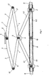
- Fig. 1 den Stellantrieb nach der Erfindung in Draufsicht,
- Fig. 2 den Gegenstand nach Fig. 1 in Seitenansicht,
- Fig. 3 den Gegenstand nach Fig. 1 in entsprechender Darsteluung, jedoch in Grundstellung.
- Der in der Zeichnung dargestellte Stellantrieb ist für die Betätigung von Fenstern, insbes. von Klappfenstern an Wintergärten und Gewächshäusern vorgesehen. Der Stellantrieb besteht aus zwei etwa in ihrer Mitte scherenartig schwenkbar miteinander verbundenen Stellhebeln 1, die jeweils mit ihrem einen Arm 1.2 endseitig an gegeneinander verstell- und antreibbaren Halteböcken 2 angeschlossen sind. An ihrem entgegengesetzten Ende sind die Stellhebel 1 gelenkig an zwei Betätigungshebel 3 angeschlossen, die wiederum mit ihrem anderen Ende schwenkbar an einem Anschlußglied 4 gelagert sind. Das Anschlußglied 4 dient der Befestigung des Stellantriebes an dem in der Zeichnung nicht dargestellten Fenster.
- Die Stellhebel 1 sind in der zu ihrer Schwenkachse senkrechten Ebene abgewinkelt und bilden somit auf der den Halteböcken zugewandten Seite einen stumpfen Winkel a. Dabei ist die Abwinklung im Bereich des die beiden Stellhebel 1 verbindenden Gelenks 5 angeordnet. Das Maß der Abwinklung ist im einzelnen so gewählt, daß bei auf maximalen gegenseitigen Abstand verfahrenen Halteböcken 2, wie dies die Fig. 3 zeigt, die mit den Betätigungshebeln 3 verbundenen Arme 1.1 der Stellhebel 1 im wesentlichen parallel zur Verstellrichtung der Halteböcke 2 verlaufen. Dadurch liegen die Gelenke 5 und 12 etwa auf einer Geraden. Wird der Stellantrieb aus dieser Grundstellung heraus verstellt, so ist durch die Verlagerung des Gelenks 5 weg von der Wirkungsgeraden der über die Halteböcke 2 an den Stellhebeln 1 angreifenden Kraft die in Längsrichtung des Hebelarms 1.2 angreifende Kraftkomponente erheblich verringert.
- Bei den aus der Zeichnung hervorgehenden Abmessungen des Stellantriebs beträgt der von den Armen des Stellhebels gebildete stumpfe Winkel a etwa 1650. Die Betätigungshebel 3 sind im Bereich ihres Befestigungspunkts 6 am Anschlußglied 4 ebenfalls bei 7 mit einer Abwinklung versehen, deren Verlauf der Abwinklung der Stellhebel entspricht.
- Die Halteböcke 2 sind zu ihrer gegenseitigen Verstellung mit einer Gewindebohrung auf einer Gewindespindel 8 angeordnet, die beidseits ihrer zwischen den Halteböcken 2 liegenden Mitte mit jeweils einem Gewinde 8.1, 8.2 mit zueinander gegenläufigem Gewindesinn versehen ist. Um eine besonders gute und reibungsfreie Verstellbarkeit zu erreichen, sind die Gewinde 8.1, 8.2 viergängig ausgeführt. Die Gewindespindel 8 ist in axialer Richtung hohl zur Aufnahme einer Antriebswelle 9 ausgebildet. Auf diese Antriebswelle 9 können in in der Zeichnung nicht näher dargestellter Weise mehrere solcher Spindeln 8 aufgeschoben sein, so daß durch den Antrieb der Antriebswelle 9 mehrere Fenster gleichzeitig betätigt werden können. Zur drehfesten Verbindung mit der Antriebswelle 9 weist die Gewindespindel 8 zumindest einen radial verlaufenden Gewindestift 10 auf, der an seiner an der Antriebswelle 9 zur Anlage kommenden Fläche als Schneidring ausgebildet sein kann. Dadurch ist es möglich, mehrere Stellantriebe bei gelöstem Gewindestift 10 durch Verdrehen der Gewindespindel 8 gegenüber der Antriebswelle 9 so zueinander zu justieren, daß die einzelnen Fenster gemeinsam schließen. Der Gewindestift 10 ist im einzelnen zwischen den beiden gegenläufigen Gewinden 8.1, 8.2 angeordnet.
- Die Halteböcke 2 weisen quaderförmige Gestalt auf und sind mit einem sich in Rihtung der Spindelachse erstreckenden, zu dem Anschlußglied 4 hin offenen Führungsspalt 11 für die Stellhebel 1 versehen. Um besonders gute Verstelleigenschaften bei geringer Reibungskraft zu erreichen,bestehen die Halteböcke 2 aus Polyamid. Ein besonders wartungsfreier Betrieb wird im übrigen dadurch erreicht, daß die Lagergelenke 4, 5, 12 von Messingbüchsen gebildet sind.
Claims (13)
Priority Applications (1)
| Application Number | Priority Date | Filing Date | Title |
|---|---|---|---|
| AT86107660T ATE51930T1 (de) | 1985-06-28 | 1986-06-05 | Stellantrieb fuer fenster, insbesondere klappfenster. |
Applications Claiming Priority (2)
| Application Number | Priority Date | Filing Date | Title |
|---|---|---|---|
| DE3523222 | 1985-06-28 | ||
| DE19853523222 DE3523222A1 (de) | 1985-06-28 | 1985-06-28 | Stellantrieb fuer fenster, insbes. klappfenster |
Publications (3)
| Publication Number | Publication Date |
|---|---|
| EP0206035A2 true EP0206035A2 (de) | 1986-12-30 |
| EP0206035A3 EP0206035A3 (en) | 1987-05-13 |
| EP0206035B1 EP0206035B1 (de) | 1990-04-11 |
Family
ID=6274489
Family Applications (1)
| Application Number | Title | Priority Date | Filing Date |
|---|---|---|---|
| EP86107660A Expired - Lifetime EP0206035B1 (de) | 1985-06-28 | 1986-06-05 | Stellantrieb für Fenster, insbesondere Klappfenster |
Country Status (3)
| Country | Link |
|---|---|
| EP (1) | EP0206035B1 (de) |
| AT (1) | ATE51930T1 (de) |
| DE (2) | DE3523222A1 (de) |
Cited By (2)
| Publication number | Priority date | Publication date | Assignee | Title |
|---|---|---|---|---|
| WO1993020318A1 (de) * | 1992-04-01 | 1993-10-14 | Emka Beschlagteile Gmbh & Co. Kg | Scharnier |
| US5535551A (en) * | 1995-02-10 | 1996-07-16 | V. Kann Rasmussen Industri A/S | Electrical window operator |
Families Citing this family (1)
| Publication number | Priority date | Publication date | Assignee | Title |
|---|---|---|---|---|
| CN108756588A (zh) * | 2018-06-06 | 2018-11-06 | 何灿权 | 一种基于智能家居用可远程控制开关的窗户 |
Family Cites Families (6)
| Publication number | Priority date | Publication date | Assignee | Title |
|---|---|---|---|---|
| FR712299A (fr) * | 1931-02-28 | 1931-09-29 | Fages Et Vene Ets | Dispositif de commande de châssis, d'impostes ou d'objets similaires |
| GB749419A (en) * | 1954-08-13 | 1956-05-23 | Teleflex Prod Ltd | Improvements in and relating to mechanism for the opening and closing of windows, louvres or the like |
| CH324587A (fr) * | 1955-10-31 | 1957-10-15 | Marguelisch Arthur | Dispositif de manoeuvre d'un panneau basculant, notamment d'une fenêtre |
| AT296074B (de) * | 1967-10-12 | 1972-01-25 | Mayer & Co Beschlaegefabrik | Vorrichtung zum Öffnen, Verschließen und zur Verriegelung von Oberlichten |
| DE3119103A1 (de) * | 1981-05-14 | 1982-12-02 | Samaritter, geb. Kornasowa, Vera, 5090 Leverkusen | Vorrichtung zum verstellen von fenstern, fenstertueren und oder auch, verfahren zu ihrer ausfuehrung |
| EP0117270A1 (de) * | 1983-02-28 | 1984-09-05 | Johannes Lock Windenfabrik und Maschinenbau | Zahnstangentrieb, insbesondere zur Betätigung von Fensterflügeln |
-
1985
- 1985-06-28 DE DE19853523222 patent/DE3523222A1/de not_active Withdrawn
-
1986
- 1986-06-05 EP EP86107660A patent/EP0206035B1/de not_active Expired - Lifetime
- 1986-06-05 DE DE8686107660T patent/DE3670337D1/de not_active Expired - Fee Related
- 1986-06-05 AT AT86107660T patent/ATE51930T1/de not_active IP Right Cessation
Cited By (3)
| Publication number | Priority date | Publication date | Assignee | Title |
|---|---|---|---|---|
| WO1993020318A1 (de) * | 1992-04-01 | 1993-10-14 | Emka Beschlagteile Gmbh & Co. Kg | Scharnier |
| US5519920A (en) * | 1992-04-01 | 1996-05-28 | Emka Beschalagteile Gmbh & Co. Kg | Hinge |
| US5535551A (en) * | 1995-02-10 | 1996-07-16 | V. Kann Rasmussen Industri A/S | Electrical window operator |
Also Published As
| Publication number | Publication date |
|---|---|
| EP0206035B1 (de) | 1990-04-11 |
| ATE51930T1 (de) | 1990-04-15 |
| DE3523222A1 (de) | 1987-01-02 |
| DE3670337D1 (de) | 1990-05-17 |
| EP0206035A3 (en) | 1987-05-13 |
Similar Documents
| Publication | Publication Date | Title |
|---|---|---|
| DE3536747C2 (de) | ||
| EP0000877B1 (de) | Manipulator zum Positionieren von Werkstücken oder anderen Lasten | |
| DE1811719B2 (de) | Vorrichtung zum Reinigen von Behältern | |
| WO1993025415A1 (de) | Antriebsvorrichtung eines scheibenwischers für ein kraftfahrzeug | |
| DE69600971T2 (de) | Elektrische fensterbedienung | |
| DE3026904C2 (de) | Verschiebbare Lagerung für ein Wellen- bzw. Walzenlager | |
| EP0186222A2 (de) | Handbetätigtes Schneidgerät | |
| EP0244578B1 (de) | Elektromotorisch angetriebene Schwenkvorrichtung | |
| DE3347697A1 (de) | Kraftbetriebenes einstellgeraet zur drehverstellung einer gewindespindel, insbesondere einer spurstange von kraftfahrzeugen | |
| DE8511244U1 (de) | Industrieroboter mit Schwenkarm | |
| DE1559776C3 (de) | FensterverschluB | |
| EP0206035B1 (de) | Stellantrieb für Fenster, insbesondere Klappfenster | |
| DE3737040C2 (de) | ||
| DE69305212T2 (de) | Fahrzeugfensterhebervorrichtung | |
| DE3513056A1 (de) | Gelenk-antriebsanordnung | |
| DE4212996C1 (de) | ||
| DE3028318A1 (de) | Aussenspiegel mit wischer | |
| DE2906102A1 (de) | Elektrisch verstellbarer aussenrueckblickspiegel fuer fahrzeuge | |
| DE19544594A1 (de) | Pendeltür | |
| DE3605945C2 (de) | Aussenrückblickspiegel für Kraftfahrzeuge | |
| DE8902621U1 (de) | Getriebe zum Verschieben eines Hubglieds | |
| EP4389023B1 (de) | Lenkgetriebe für ein chirurgisches instrument und damit ausgestattetes chirurgisches instrument | |
| EP2905409A1 (de) | Stellvorrichtung für einen Flügel sowie Vorrichtung zur Einstellung von mehreren Flügeln | |
| DE2502189A1 (de) | Rueckblickspiegel fuer kraftfahrzeuge oder dgl. | |
| EP1477086A1 (de) | Drehantrieb |
Legal Events
| Date | Code | Title | Description |
|---|---|---|---|
| PUAI | Public reference made under article 153(3) epc to a published international application that has entered the european phase |
Free format text: ORIGINAL CODE: 0009012 |
|
| AK | Designated contracting states |
Kind code of ref document: A2 Designated state(s): AT BE CH DE FR GB IT LI LU NL SE |
|
| PUAL | Search report despatched |
Free format text: ORIGINAL CODE: 0009013 |
|
| AK | Designated contracting states |
Kind code of ref document: A3 Designated state(s): AT BE CH DE FR GB IT LI LU NL SE |
|
| 17P | Request for examination filed |
Effective date: 19870918 |
|
| 17Q | First examination report despatched |
Effective date: 19881122 |
|
| GRAA | (expected) grant |
Free format text: ORIGINAL CODE: 0009210 |
|
| AK | Designated contracting states |
Kind code of ref document: B1 Designated state(s): AT BE CH DE FR GB IT LI LU NL SE |
|
| REF | Corresponds to: |
Ref document number: 51930 Country of ref document: AT Date of ref document: 19900415 Kind code of ref document: T |
|
| ITF | It: translation for a ep patent filed | ||
| REF | Corresponds to: |
Ref document number: 3670337 Country of ref document: DE Date of ref document: 19900517 |
|
| ET | Fr: translation filed | ||
| GBT | Gb: translation of ep patent filed (gb section 77(6)(a)/1977) | ||
| PLBI | Opposition filed |
Free format text: ORIGINAL CODE: 0009260 |
|
| 26 | Opposition filed |
Opponent name: GEZE GMBH & CO. Effective date: 19910109 |
|
| NLR1 | Nl: opposition has been filed with the epo |
Opponent name: GEZE GMBH & CO. |
|
| PGFP | Annual fee paid to national office [announced via postgrant information from national office to epo] |
Ref country code: SE Payment date: 19910606 Year of fee payment: 6 |
|
| ITTA | It: last paid annual fee | ||
| PGFP | Annual fee paid to national office [announced via postgrant information from national office to epo] |
Ref country code: NL Payment date: 19910630 Year of fee payment: 6 |
|
| PGFP | Annual fee paid to national office [announced via postgrant information from national office to epo] |
Ref country code: CH Payment date: 19911108 Year of fee payment: 6 |
|
| PGFP | Annual fee paid to national office [announced via postgrant information from national office to epo] |
Ref country code: AT Payment date: 19911115 Year of fee payment: 6 |
|
| PGFP | Annual fee paid to national office [announced via postgrant information from national office to epo] |
Ref country code: FR Payment date: 19911218 Year of fee payment: 6 |
|
| PLBN | Opposition rejected |
Free format text: ORIGINAL CODE: 0009273 |
|
| STAA | Information on the status of an ep patent application or granted ep patent |
Free format text: STATUS: OPPOSITION REJECTED |
|
| 27O | Opposition rejected |
Effective date: 19911125 |
|
| NLR2 | Nl: decision of opposition | ||
| PG25 | Lapsed in a contracting state [announced via postgrant information from national office to epo] |
Ref country code: AT Effective date: 19920605 |
|
| PG25 | Lapsed in a contracting state [announced via postgrant information from national office to epo] |
Ref country code: SE Effective date: 19920606 |
|
| PGFP | Annual fee paid to national office [announced via postgrant information from national office to epo] |
Ref country code: GB Payment date: 19920624 Year of fee payment: 7 Ref country code: BE Payment date: 19920624 Year of fee payment: 7 |
|
| PG25 | Lapsed in a contracting state [announced via postgrant information from national office to epo] |
Ref country code: LI Effective date: 19920630 Ref country code: CH Effective date: 19920630 |
|
| PGFP | Annual fee paid to national office [announced via postgrant information from national office to epo] |
Ref country code: LU Payment date: 19920630 Year of fee payment: 7 |
|
| EPTA | Lu: last paid annual fee | ||
| PG25 | Lapsed in a contracting state [announced via postgrant information from national office to epo] |
Ref country code: NL Effective date: 19930101 |
|
| NLV4 | Nl: lapsed or anulled due to non-payment of the annual fee | ||
| PG25 | Lapsed in a contracting state [announced via postgrant information from national office to epo] |
Ref country code: FR Effective date: 19930226 |
|
| REG | Reference to a national code |
Ref country code: CH Ref legal event code: PL |
|
| REG | Reference to a national code |
Ref country code: FR Ref legal event code: ST |
|
| PG25 | Lapsed in a contracting state [announced via postgrant information from national office to epo] |
Ref country code: LU Free format text: LAPSE BECAUSE OF NON-PAYMENT OF DUE FEES Effective date: 19930605 Ref country code: GB Effective date: 19930605 |
|
| PG25 | Lapsed in a contracting state [announced via postgrant information from national office to epo] |
Ref country code: BE Effective date: 19930630 |
|
| BERE | Be: lapsed |
Owner name: FIRMA KLEMENS SCHLACHTER Effective date: 19930630 |
|
| GBPC | Gb: european patent ceased through non-payment of renewal fee |
Effective date: 19930605 |
|
| PGFP | Annual fee paid to national office [announced via postgrant information from national office to epo] |
Ref country code: DE Payment date: 19940811 Year of fee payment: 9 |
|
| EUG | Se: european patent has lapsed |
Ref document number: 86107660.2 Effective date: 19930109 |
|
| PG25 | Lapsed in a contracting state [announced via postgrant information from national office to epo] |
Ref country code: DE Effective date: 19960301 |
|
| PG25 | Lapsed in a contracting state [announced via postgrant information from national office to epo] |
Ref country code: IT Free format text: LAPSE BECAUSE OF NON-PAYMENT OF DUE FEES;WARNING: LAPSES OF ITALIAN PATENTS WITH EFFECTIVE DATE BEFORE 2007 MAY HAVE OCCURRED AT ANY TIME BEFORE 2007. THE CORRECT EFFECTIVE DATE MAY BE DIFFERENT FROM THE ONE RECORDED. Effective date: 20050605 |