EP0206109A2 - Gerät zur Halterung eines optischen Einsatzes bei einer Schutzmaske - Google Patents
Gerät zur Halterung eines optischen Einsatzes bei einer Schutzmaske Download PDFInfo
- Publication number
- EP0206109A2 EP0206109A2 EP86107931A EP86107931A EP0206109A2 EP 0206109 A2 EP0206109 A2 EP 0206109A2 EP 86107931 A EP86107931 A EP 86107931A EP 86107931 A EP86107931 A EP 86107931A EP 0206109 A2 EP0206109 A2 EP 0206109A2
- Authority
- EP
- European Patent Office
- Prior art keywords
- lens
- face
- eyewire
- hinge
- mask
- Prior art date
- Legal status (The legal status is an assumption and is not a legal conclusion. Google has not performed a legal analysis and makes no representation as to the accuracy of the status listed.)
- Withdrawn
Links
Images


Classifications
-
- G—PHYSICS
- G02—OPTICS
- G02C—SPECTACLES; SUNGLASSES OR GOGGLES INSOFAR AS THEY HAVE THE SAME FEATURES AS SPECTACLES; CONTACT LENSES
- G02C9/00—Attaching auxiliary optical parts
- G02C9/02—Attaching auxiliary optical parts by hinging
-
- A—HUMAN NECESSITIES
- A62—LIFE-SAVING; FIRE-FIGHTING
- A62B—DEVICES, APPARATUS OR METHODS FOR LIFE-SAVING
- A62B18/00—Breathing masks or helmets, e.g. affording protection against chemical agents or for use at high altitudes or incorporating a pump or compressor for reducing the inhalation effort
- A62B18/08—Component parts for gas-masks or gas-helmets, e.g. windows, straps, speech transmitters, signal-devices
- A62B18/082—Assembling eyepieces, lenses or vision-correction means in or on gas-masks
Definitions
- This invention relates generally to structures supporting optically correct prescription lenses for those who must wear protective masks, and more particularly to a support structure designed to be used with foldable protective masks and to accurately locate and facilitate replacement of prescription or otherwise spezialized lenses.
- This invention may be used by those requiring vision correction and also having to wear protective masks, such as gas masks, full face respirators or welding helmets, scuba goggles, ski goggles, luge helmets and surgical masks, where ordinary spectacles with temples are impractical.
- a loop of wire or metal is attached to each frame at the location where normally a temple hinge would be found. These loops extend forward of the lenses and toward the center.
- the protective mask has a bracket near the center of the top of the face plate designed to receive the ends of the loops.
- the spectacles are suspended from the inside surface of the mask, by the metal loops.
- the loops are approximately one and one half times the diameter of each lens.
- This metal retaining ring method has several disadvantages. Prescription lenses must be located properly to ensure that the lenses will provide the optimum corrective benefit. Several terms must be defined to describe proper fitting of prescription lenses.
- the "eye-wire” is that part of the frame that encircles and retains an individual lens.
- the "vertex position” is the vertical position of the lens centers with respect to the pupils.
- the "pantoscopic angle” is the angle by which the vertical axis of the lens is inclined to a nominal vertical reference with respect to the wearer's face.
- the "face-form” angle is an angle between two planes. The two planes that define the face-form angle are the respective planes in which the perimeters of the eyewires lie.
- the lenses cannot be located accurately in front of the eye to afford optimum visual correction. It is also difficult to maintain the proper pantoscopic angle because of the inherent flexibility of the structure. Thus optimum visual correction is not provided. Similarly, proper face-form angle cannot be maintained due to the spring nose-piece. Vertical adjustment of the lenses is difficult. If the retaining rings are removed from the mask, it is difficult to reposition the lens carrier in the proper vertical position. Finally, lenses cannot be removed from the frame without using special tools, and without removing the lens carrier from the protective mask.
- a lens carrier support anchor is cemented to the inside surface of the face plate, or to the structure which supports the face plate.
- the anchor piece is designed to receive a semi-flexible tab-like member which is integral with the nose bridge of a spectacle frame.
- the frame has no temples.
- Disadvantages of this system are that the relatively flexible tab does not secure the spectacle frames in a secure position, so that the pantoscopic angle cannot be fixed.
- the face-form angle is not easily customizable.Further, it is not possible to fix the vertical adjustment, or the horizontal distance from the pupils to the lenses.
- a face mask that may be folded flat when not in use may not be folded flat when this type of a lens carrier is used.
- the support anchor attaches to the face plate with a suction cup.
- this device may be used only for brief periods of time, and is not recommended for dangerous situations because the suction cup may disengage at any time.
- the several objects of our invention include providing a support structure for protective face mask optical inserts by which: accurate, stable positioning of the optical insert may be obtained; the optical insert may be removed from one mask and easily positioned and attached to another mask; proper pantoscopic and face-form angles may be achieved; proper vertical placement and pupil to lens distances may be achieved; the lenses may be easily removed and replaced without removing the support structure from the mask; the mask and lens support structure may be folded flat while not in use and safe, reliable positioning of the optical inserts may be accomplished.
- This invention comprises a lens support that attaches to the inside of the face plate of a protective mask. It may be used with either a single plate face mask, or face masks that may be folded flat, having two face plates.
- the invention comprises a pair of lens frames joined by a hinge that makes up the nose bridge. Each individual lens frame is made up of an eyewire integrally formed with an element that makes up part of the hinged nose bridge.
- the hinge permits folding the pair of lens frames together so that the portions of the lens frames furthest away from the nose bridge almost touch.
- the hinged pair of lens frames attaches to a hinge block having a dove-tail type projection on the side facing away from the lens frames.
- the projection engages a back block provided with a suitably sized dove-tail groove.
- the back block attaches to an anchor that attaches to the face plate or to the mask adjacent the face plate.
- the prescription lenses are rigidly secured to the face mask through dove-tails of the front hinge block and the back block.
- the face of the back block that attaches to the anchor, and the opposite face of the back block, that engages the dove tail hinge block, are angularly disposed with respect to each other to provide the pantoscopic angle required by the particular wearer and mask.
- the cooperation of the front hinge block and the front surface of the hinge element of each lens frame may be customized to limit the hinged travel of the pair of lens frames, thereby adapting properly to the wearer's required face-form angle.
- the lens support may be folded flat when used with a protective mask which may be folded flat during non-use. Further, the lens supporting frames may be folded inward, and the lenses may be removed by popping them out from the rear.
- a lens and lens frame system which permits snapping a lens into the lens frame from the front with only finger pressure, and also removing the lens by simply snapping the lens out, is also described.
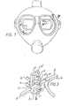
- Fig. 1 shows schematically a person wearing a protective face mask, and also using prescription or special lenses carried by a lens support. It can be seen, that once the mask is in place, adjustment of the lens support is impossible. Therefore the lens support must be secured so that the position relative to the user's eyes is reproduceable. Further, it can be seen that standard eye glasses with temples are impractical and uncomfortable, due to the wrap around features of the protective mask.
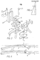
- FIG. 2 shows an exploded view of the elements of a preferred embodiment of our invention.
- Elements 1 are a pair of lens carrying frames, each frame made up of an eyewire 2 and a hinge portion 4.
- the eyewires are of a type designed to releasably engage lenses merely by snapping the lenses into place from the front.
- the eyewires are provided with a series of tabs (not shown) around the forward aperture of the eyewire, which engage the lens when the lens is snapped into place.
- This type of eyewire and lens system is described in the following in the context of figs. 7 to 11 and more fully in co-pending co-assigned U.S. patent application no.
- each lens frame is provided with a hole 7 designed to receive the arms 9 of a pair of torsion springs 11.
- the two lens frames are fit together with hinge lobe 5 sliding between hinge lobes 3.
- the torsion springs 11 are fitted into holes 7 on the top and bottom of the frames. When so joined, the spaces 17 formed by the looped torsion springs align with holes 13 and 15 in the hinge lobes 3 and 5 respectively.
- Front hinge block 19 secures the torsion springs and the lens frames between upper and lower hinge block lobes 21 like a sandwich.
- Hinge pin 23 passes through holes 25 in hinge block lobes 21 and through spaces 17 in torsion springs 11 and holes 13 and 15 in hinge lobes 3 and 5.
- the hinge pin 23 may be secured by threading into the lower hinge block lobe 21, by plastic heat fusion methods, by a threaded nut (not shown) or by any wellknown means.
- the vertex position of the lens frames is established by placing the front hinge block 27 in the proper vertical position with respect to the back block 25. As described below, the back block is rigidly fixed with respect to the mask.
- the front hinge block is provided with a dove-tail projection 27, which slideably engages the dove-tail recess 29 in back block 25.
- Set screw 31 secures the hinge block in proper vertical location.
- the back block and anchor piece 33 are attached to the protective mask. This may be accomplished by several means.
- the anchor 33 may be permanently attached to the structural element by any suitable means, including adhesives, heat sealing, or mechanical means.
- the back block 25 is permanently attached to the anchor piece 33.
- the back block is made up of a solid having a trapezoidal cross-section, with a dove-tail groove along one of the longer faces. As can be seen in fig.
- the forward face 35 (facing the ancor) is inclined with respect to the rearward face 37 (facing the hinge block).
- Changing this angle A permits customizing the pantoscopic angle.
- the pantoscopic angle must be customized for each particular user, and further if the user uses different protective masks having different structures, it may be necessary to realign the placement of the lens carrying support structure with respect to the mask and the portions of the support structure that anchor the lens carrier to the mask. Therefore, several different back blocks may be used by each user.
- each lens frame is made up of a hinge portion 4 adjacent the hinge lobes, and an eyewire 1 which generally surrounds the lens.
- the hinge portion 4 contacts the face plane 43 of the front hinge block.
- An eyewire angle f is defined by the intersection of the front surface of the hinge portion 4 and the forward plane of the eyewire 1.
- the eyewire is inclined at eyewire angle f with respect to the face plane 43.
- This eyewire angle f defines the face-form angle.
- the proper face-form angel may be obtained by properly preparing the eyewire angle f.
- This angle is either molded into the frames during fabrication, or, alternatively, it may be applied by heating and bending the frame during initial fitting of the frames.
- Each of the eyewires 2 is designed to receive a lens 107.
- the shape of the rim recess is adapted to match the perimeter of the lens 107.
- the edge of the lens is beveled, indicated generally at 111.
- the rear aperture of the eyewire 2 is provided with a flange, generally indicated at 113 (see also fig. 9).
- the flange 113 is inclined so as to match the angle of the bevel 111 and support the lens 107 when the lens is inserted into the eyewire recess.
- the cooperation of the bevel 111 and the rear aperture flange 113 may best be seen with reference to either fig. 8.
- Tabs 115 are spaced around the perimeter of the forward aperture of the eyewire recess.
- the tabs 115 may be located at any point of the eyewire.
- Two tabs may be adequately sized to hold the lens in place. It has been found that in the case three tabs are used, better results are obtained if two tabs are placed closer to each other than either is to the third tab.
- the tabs must be of a height h (fig. 8), small enough to permit snapping the lens into the eyewire over the tab when the frame is flexed, but large enough to retain the lens in the eyewire when no flexure is applied. In the case of a lens having a bevel angle B of 57.5 degrees, h equal to 0.8 mm (.03 inches) has been found to be sufficient.
- the method of removal of the lens can best be seen with reference to fig. 7. Pressure is simply applied to the lens and the lens is pushed in the direction of the arrow F. At the same time, the eyewire 2 is flexed so as to slightly move tab 115 out of the way of the lens. Thus the lens 107 may be removed, and replaced with another lens of the same shape. Alternatively the lens 107 may be placed into frames having different characteristics.
- the rear flange 113 is interrupted around its perimeter at locations corresponding to the retaining tabs on the front aperture. This interruption permits fabrication by a two mold process, because the interruptions in the rear flange permit mold access to the rear face of the retaining tabs. Likewise, the absence of the retaining tabs around most of the forward aperture, permits mold access to the front face of the rear flange.
- this invention is easy to manufacture. Any ordinary eyeglass frame plastic may be used. Because the tabs are integral with the frame, and of a durable shape an size, they will withstand many exchanges of lenses before wearing out. Further, standard beveled edge lenses may be used, thereby minimizing the cost of this exchangeable lens system.
- the rear facing aperture flange need not extend for the entire perimeter of the eyewire. It need only be of such a length sufficient to retain the lens in the frame and to prevent the lens from being pushed into the user's eyes in the case of impact. Further, the lens need not be beveled in the rearward direction, and similarly, the rear facing aperture need not be angled so as to match a bevel.
- the rear facing aperture and the recess defined thereby may be L-shaped. In that case, the rear facing surface of the lens and the rearward portion of the edge should be formed in a right angle to match with the L-shape of the recess.
- the lens and frame combination is provided where small tabs around the forward aperture of the inside ring of the lens-holding frame secure the lens in the frame, once the lens has been snapped in place.
- the lens may be easily removed and replaced simply by hand.
- a user desiring to exchange lenses simply folds the lens frame away from the face plate of the mask, and snaps the lens out from the lens frame pushing from the rear to the front (in the direction of the arrow X).
- the user inserts a replacement lens from the front to the rear and unfolds the lens frames back to the original position.
- This feature is also advantageous if the protective face mask becomes damaged, and the user needs to remove the lenses to another face mask and lens carrier combination.
- the lenses may be removed, and snapped into place in another mask. This feature reduces the cost of outfitting a user with a wide variety of masks, as the cost of manufacturing the prescription lenses must only be borne once.
- the entire protective mask and lens support structure may be folded flat during periods of non-use.
- the pantoscopic angle may be precisely adapted for the induvidual wearer and mask combination. Once installed in the face mask, this angle will not be altered by the user.
- the face-form angle is also precisely adaptable for the particular wearer.
- the vertical adjustability feature allows for the vertex dimension to be set and maintained.
- the embodiment of the invention shown in fig. 5 contemplates a permanent fixture of anchor 33 to the structural area between the left and right face plates of the face mask.
- the invention may also be practiced with a single face plate type mask. In that case, the anchor 33 would either be attached to the face plate with adhesive, or attached to a structural portion of the mask immediately adjacent the central upper edge of the face plate.
Landscapes
- Health & Medical Sciences (AREA)
- Physics & Mathematics (AREA)
- General Physics & Mathematics (AREA)
- Ophthalmology & Optometry (AREA)
- Optics & Photonics (AREA)
- Pulmonology (AREA)
- General Health & Medical Sciences (AREA)
- Business, Economics & Management (AREA)
- Emergency Management (AREA)
- Eyeglasses (AREA)
Applications Claiming Priority (4)
| Application Number | Priority Date | Filing Date | Title |
|---|---|---|---|
| US74288485A | 1985-06-10 | 1985-06-10 | |
| US742884 | 1985-06-10 | ||
| US06/746,178 US4711539A (en) | 1985-06-18 | 1985-06-18 | Support structure for protective mask optical insert |
| US746178 | 1985-06-18 |
Publications (2)
| Publication Number | Publication Date |
|---|---|
| EP0206109A2 true EP0206109A2 (de) | 1986-12-30 |
| EP0206109A3 EP0206109A3 (de) | 1989-11-23 |
Family
ID=27114069
Family Applications (1)
| Application Number | Title | Priority Date | Filing Date |
|---|---|---|---|
| EP86107931A Withdrawn EP0206109A3 (de) | 1985-06-10 | 1986-06-10 | Gerät zur Halterung eines optischen Einsatzes bei einer Schutzmaske |
Country Status (1)
| Country | Link |
|---|---|
| EP (1) | EP0206109A3 (de) |
Cited By (3)
| Publication number | Priority date | Publication date | Assignee | Title |
|---|---|---|---|---|
| FR2620023A1 (fr) * | 1987-09-03 | 1989-03-10 | American Optical Corp | Dispositif oculaire de protection avec piece nasale amovible et lunettes correctrices |
| EP0656558A1 (de) * | 1993-12-03 | 1995-06-07 | KILLER LOOP S.p.A. | Verbindungsverfahren, insbesondere für Brillenlinsen |
| AT505016B1 (de) * | 2007-11-22 | 2008-10-15 | Steinle Markus | Brille, insbesondere sportbrille |
Family Cites Families (5)
| Publication number | Priority date | Publication date | Assignee | Title |
|---|---|---|---|---|
| US2445203A (en) * | 1945-01-15 | 1948-07-13 | Fibre Metal Products Company | Headgear goggles |
| US2905172A (en) * | 1957-01-07 | 1959-09-22 | Acme Prot Equipment Company | Eyeglass mounting for gas masks |
| US3004535A (en) * | 1960-03-01 | 1961-10-17 | Carl A Nielson | Optical insert for gas masks |
| DE1254022B (de) * | 1961-04-29 | 1967-11-09 | Felix Wulkow Dr Med | Atemschutzmaske mit einer an ihrer Innenseite angeordneten Brille |
| US3563640A (en) * | 1968-08-12 | 1971-02-16 | Mine Safety Appliances Co | Device for holding spectacles in a mask |
-
1986
- 1986-06-10 EP EP86107931A patent/EP0206109A3/de not_active Withdrawn
Cited By (4)
| Publication number | Priority date | Publication date | Assignee | Title |
|---|---|---|---|---|
| FR2620023A1 (fr) * | 1987-09-03 | 1989-03-10 | American Optical Corp | Dispositif oculaire de protection avec piece nasale amovible et lunettes correctrices |
| EP0656558A1 (de) * | 1993-12-03 | 1995-06-07 | KILLER LOOP S.p.A. | Verbindungsverfahren, insbesondere für Brillenlinsen |
| US5659381A (en) * | 1993-12-03 | 1997-08-19 | Killer Loop S.P.A. | Engagement device particularly for lenses of eyeglasses |
| AT505016B1 (de) * | 2007-11-22 | 2008-10-15 | Steinle Markus | Brille, insbesondere sportbrille |
Also Published As
| Publication number | Publication date |
|---|---|
| EP0206109A3 (de) | 1989-11-23 |
Similar Documents
| Publication | Publication Date | Title |
|---|---|---|
| US4711539A (en) | Support structure for protective mask optical insert | |
| US4810080A (en) | Protective eyewear with removable nosepiece and corrective spectacle | |
| US4834525A (en) | Visual aid device | |
| US5608470A (en) | Prescription lens attachable to safety glasses | |
| US5493348A (en) | Means for mounting a prescription lens accessory onto a pair of glasses | |
| US7370961B2 (en) | Interchangeable eyewear assembly | |
| US20050200802A1 (en) | Multi-faceted magnetic hinge system for coupling objects, including eyewear | |
| US5579062A (en) | Interchangeable lens eyeglasses with temple release mechanism | |
| US5900922A (en) | Eyewear having a unitary flexible frame and an interchangeable lens | |
| US12541121B2 (en) | Eyewear with engageable protective shield | |
| US4618225A (en) | Lens holder and carrier for safety masks | |
| CA2306903A1 (en) | Optical lens | |
| EP0206109A2 (de) | Gerät zur Halterung eines optischen Einsatzes bei einer Schutzmaske | |
| JP3188129B2 (ja) | 眼鏡体におけるレンズ部への視力矯正用レンズ取付方法 | |
| US5406337A (en) | Semi-rimless eyeglass frame assembly | |
| US1923567A (en) | Ophthalmic mounting | |
| CN101466334B (zh) | 具有柔性缆线附件的护目镜 | |
| CA2806245C (en) | Safety, sport or recreational eyewear with interchangeable optical prescription pvc foil insert | |
| EP0184929A1 (de) | Atemschutzgerät mit Befestigungseinrichtung für Korrekturgläser | |
| CN117666142A (zh) | 具有可移除透镜的系统 | |
| US4101208A (en) | Ophthalmic device for tensionally securing lenses thereto | |
| AU750905B2 (en) | Adapter for fixing spectacle lenses | |
| US20250271685A1 (en) | Adaptable eyewear frame and method of using the same | |
| WO2000070387A1 (en) | Eyewear assembly and method for obtaining the same | |
| JPH08286158A (ja) | 簡易眼鏡の視力矯正用レンズの位置決め具および簡易眼鏡の視力矯正用レンズの位置決め方法 |
Legal Events
| Date | Code | Title | Description |
|---|---|---|---|
| PUAI | Public reference made under article 153(3) epc to a published international application that has entered the european phase |
Free format text: ORIGINAL CODE: 0009012 |
|
| AK | Designated contracting states |
Kind code of ref document: A2 Designated state(s): AT BE CH DE FR GB IT LI LU NL SE |
|
| PUAL | Search report despatched |
Free format text: ORIGINAL CODE: 0009013 |
|
| AK | Designated contracting states |
Kind code of ref document: A3 Designated state(s): AT BE CH DE FR GB IT LI LU NL SE |
|
| RHK1 | Main classification (correction) |
Ipc: A62B 18/08 |
|
| 17P | Request for examination filed |
Effective date: 19900410 |
|
| 17Q | First examination report despatched |
Effective date: 19910611 |
|
| STAA | Information on the status of an ep patent application or granted ep patent |
Free format text: STATUS: THE APPLICATION IS DEEMED TO BE WITHDRAWN |
|
| 18D | Application deemed to be withdrawn |
Effective date: 19930210 |
|
| RIN1 | Information on inventor provided before grant (corrected) |
Inventor name: GRENDOL, CLARK Inventor name: PIENTA, JOSEPH J. Inventor name: KRUSAS, JAMES J. |