EP0206125A2 - Zylinderkopf für flüssigkeitsgekühlte Brennkraftmaschinen - Google Patents
Zylinderkopf für flüssigkeitsgekühlte Brennkraftmaschinen Download PDFInfo
- Publication number
- EP0206125A2 EP0206125A2 EP86107983A EP86107983A EP0206125A2 EP 0206125 A2 EP0206125 A2 EP 0206125A2 EP 86107983 A EP86107983 A EP 86107983A EP 86107983 A EP86107983 A EP 86107983A EP 0206125 A2 EP0206125 A2 EP 0206125A2
- Authority
- EP
- European Patent Office
- Prior art keywords
- cylinder head
- liquid
- cooling
- valve
- cooling channels
- Prior art date
- Legal status (The legal status is an assumption and is not a legal conclusion. Google has not performed a legal analysis and makes no representation as to the accuracy of the status listed.)
- Granted
Links
- 238000002485 combustion reaction Methods 0.000 title claims abstract description 11
- 238000001816 cooling Methods 0.000 claims abstract description 51
- 239000007788 liquid Substances 0.000 claims abstract description 28
- 238000002347 injection Methods 0.000 claims abstract description 10
- 239000007924 injection Substances 0.000 claims abstract description 10
- 239000000110 cooling liquid Substances 0.000 claims description 6
- 238000013021 overheating Methods 0.000 abstract description 4
- 238000007789 sealing Methods 0.000 abstract description 3
- XLYOFNOQVPJJNP-UHFFFAOYSA-N water Substances O XLYOFNOQVPJJNP-UHFFFAOYSA-N 0.000 description 6
- 239000002826 coolant Substances 0.000 description 4
- 230000035515 penetration Effects 0.000 description 3
- 238000005266 casting Methods 0.000 description 1
- 238000004939 coking Methods 0.000 description 1
- 239000010687 lubricating oil Substances 0.000 description 1
Images

Classifications
-
- F—MECHANICAL ENGINEERING; LIGHTING; HEATING; WEAPONS; BLASTING
- F01—MACHINES OR ENGINES IN GENERAL; ENGINE PLANTS IN GENERAL; STEAM ENGINES
- F01P—COOLING OF MACHINES OR ENGINES IN GENERAL; COOLING OF INTERNAL-COMBUSTION ENGINES
- F01P3/00—Liquid cooling
- F01P3/12—Arrangements for cooling other engine or machine parts
- F01P3/14—Arrangements for cooling other engine or machine parts for cooling intake or exhaust valves
-
- F—MECHANICAL ENGINEERING; LIGHTING; HEATING; WEAPONS; BLASTING
- F01—MACHINES OR ENGINES IN GENERAL; ENGINE PLANTS IN GENERAL; STEAM ENGINES
- F01P—COOLING OF MACHINES OR ENGINES IN GENERAL; COOLING OF INTERNAL-COMBUSTION ENGINES
- F01P3/00—Liquid cooling
- F01P3/02—Arrangements for cooling cylinders or cylinder heads
-
- F—MECHANICAL ENGINEERING; LIGHTING; HEATING; WEAPONS; BLASTING
- F02—COMBUSTION ENGINES; HOT-GAS OR COMBUSTION-PRODUCT ENGINE PLANTS
- F02F—CYLINDERS, PISTONS OR CASINGS, FOR COMBUSTION ENGINES; ARRANGEMENTS OF SEALINGS IN COMBUSTION ENGINES
- F02F1/00—Cylinders; Cylinder heads
- F02F1/24—Cylinder heads
- F02F1/26—Cylinder heads having cooling means
- F02F1/36—Cylinder heads having cooling means for liquid cooling
- F02F1/38—Cylinder heads having cooling means for liquid cooling the cylinder heads being of overhead valve type
-
- F—MECHANICAL ENGINEERING; LIGHTING; HEATING; WEAPONS; BLASTING
- F02—COMBUSTION ENGINES; HOT-GAS OR COMBUSTION-PRODUCT ENGINE PLANTS
- F02B—INTERNAL-COMBUSTION PISTON ENGINES; COMBUSTION ENGINES IN GENERAL
- F02B75/00—Other engines
- F02B75/16—Engines characterised by number of cylinders, e.g. single-cylinder engines
- F02B75/18—Multi-cylinder engines
- F02B2075/1804—Number of cylinders
- F02B2075/1812—Number of cylinders three
-
- F—MECHANICAL ENGINEERING; LIGHTING; HEATING; WEAPONS; BLASTING
- F02—COMBUSTION ENGINES; HOT-GAS OR COMBUSTION-PRODUCT ENGINE PLANTS
- F02B—INTERNAL-COMBUSTION PISTON ENGINES; COMBUSTION ENGINES IN GENERAL
- F02B3/00—Engines characterised by air compression and subsequent fuel addition
- F02B3/06—Engines characterised by air compression and subsequent fuel addition with compression ignition
-
- F—MECHANICAL ENGINEERING; LIGHTING; HEATING; WEAPONS; BLASTING
- F02—COMBUSTION ENGINES; HOT-GAS OR COMBUSTION-PRODUCT ENGINE PLANTS
- F02F—CYLINDERS, PISTONS OR CASINGS, FOR COMBUSTION ENGINES; ARRANGEMENTS OF SEALINGS IN COMBUSTION ENGINES
- F02F1/00—Cylinders; Cylinder heads
- F02F1/24—Cylinder heads
- F02F2001/244—Arrangement of valve stems in cylinder heads
- F02F2001/247—Arrangement of valve stems in cylinder heads the valve stems being orientated in parallel with the cylinder axis
Definitions
- the invention relates to a cylinder head for liquid-cooled internal combustion engines according to the preamble of claim 1.
- DE-PS 28 39 199 describes a cylinder head for a liquid-cooled, especially water-cooled internal combustion engine with a cooling channel lying longitudinally to the row of cylinders and intersecting two water spaces per cylinder.
- a transverse channel which is directed obliquely to the row of cylinders to the other and uerkanälen Q performs parallel, on the opposite side of the longitudinal duct of the cylinder head.
- one transverse channel leads between two adjacent cylinders and cuts two further water spaces, while the other leads between an inlet and outlet channel or an inlet and outlet valve of a cylinder.
- Both transverse channels open into additional water spaces which, like all other water spaces, are arranged essentially around the cylinders.
- the water spaces are connected to a cooling space surrounding the cylinder tube.
- the liquid flows into the cylinder head via the cooling chamber.
- the longitudinal channel forms the liquid drain.
- a disadvantage of this arrangement is that the components which are subjected to high temperatures are not cooled uniformly from all sides and thus overheating and becoming out of round the valve seat rings, valve ridges and warping of the sealing surface between the cylinder head and cylinder tube cannot be completely avoided.
- the object of the invention is to specifically cool the temperature-sensitive components in the cylinder head, but without intensively cooling the cylinder head as a whole.
- the object is achieved in a generic cylinder head by the characterizing features of the first claim.
- Engine lubricating oil is particularly suitable as a coolant.
- a respective F lüsstechnikszufluß between two adjacent cylinders arranged and starting from the liquid flow duct cooling channels for respectively more remote input or exhaust valve of the adjacent cylinders.
- the cooling channels open into a valve ring channel, which at least partially encloses the inlet and outlet valves.
- Is an opening in the cylinder head base is provided for receiving an injection nozzle holder, it is useful as the cooling channels carrying the same to the V entilringkanal of the inlet and exhaust valve cylinder cross leader liquid under the injection nozzle holder. This ensures intensive cooling of this temperature-sensitive component.
- valve ring channels with the annular groove.
- liquid inflow is formed by a longitudinal channel running parallel to the row of cylinders.
- the cooling passages and bores belonging to the outlet valve have a larger effective cross section for the cooling liquid than those belonging to the inlet valve.
- the inflow of liquid takes place through the tie rod bores 2 on one side of the row of cylinders 17, the tie rod bores being arranged in the middle between two cylinders.
- the liquid inflow can also be formed by a longitudinal channel running parallel to the row of cylinders.
- a rectilinear cooling duct 3 leads in each case to the more distant inlet or outlet valve 7, 8.
- the cooling channels 3 are arranged so that they are fluidically intersect below the injection nozzle holder 4 in the penetration point 25th
- a valve ring channel 5 is arranged around each inlet and outlet valve 7, 8, which completely surrounds the valve and into which a cooling channel 3 opens.
- bores 16 are arranged which connect the valve ring channels 5 to the annular groove 12.
- the bores 16 and cooling channels 3 are expediently drilled after the casting, wherein they are subsequently closed off in a liquid-tight manner by means of plugs 1.
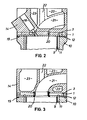
- FIG. 2 shows a section through the cylinder head 14 just described with an adjacent cylinder tube 9, the section being made through the injection nozzle 18 in the axial direction.
- the annular cooling space 11 can be seen, which is in an open, fluid-carrying connection to the annular groove 12 in the cylinder head 14.
- a seal 19 is arranged in the housing 10 and prevents the coolant from escaping. The tightness between cylinder head 14 and cylinder tube 9 is brought about by metallic contact of the parts to be sealed.
- the injection nozzle 18 can be seen and below the penetration point 25 of the cooling channels 3.
- the cooling channels 3, which are closed to the outside by plugs 1, the Venilsitz 20 of the exhaust valve 8 and the exhaust port 21 with a bore for the liner are shown in dashed lines 22 of the exhaust valve stem. Above the cooling channels 3 there is also a space 23 which can be filled with cooling liquid for cooling.
- Fig. 3 is similar to Fig. 2, except that the cut was made along the cooling channels 3. It can be clearly seen how the annular cooling space 11 in the cylinder tube 9 is connected via the annular groove 12 to the cooling channels 3, which are closed to the outside by plugs 1.
- the valve seat 20, from which the outlet channel 21 extends, is arranged in the cylinder head 14 in the center above the cylinder tube axis. A bore is provided for a liner 22 (not shown) for the valve stem.
- the outlet valve 8 surround spaces 23 which can be filled with cooling liquid for cooling.
- the coolant is conveyed into the cooling channels 3 via the tie rod holes 2. From there, a portion flows through the intersection points 13 in the annular groove 12 and the remainder a depending two cooling channels 3 intersect in the valve ring channels 5. D under the E inspritz- nozzle holder 4 in the penetration point 25, this component is particularly well cooled, as well as the inlet and outlet valves 7, 8, since these are each surrounded by a valve ring channel 5. It can also be expedient if the cooling channels 3 and bores 16 belonging to the outlet valve 8 have a larger effective cross section for the cooling liquid than those belonging to the inlet valve 7.
- the coolant passes through a bore 16, which is located in relation to the connecting line of the inlet and outlet valves 7, 8 on the side opposite the liquid inflow, into the annular groove 12 and from there into the annular cooling space 11, which between Cylinder tube 9 and housing 10 of the internal combustion engine is arranged. From the annular cooling space 11, the cooling liquid z. B. passed directly into the crankcase.
Landscapes
- Engineering & Computer Science (AREA)
- Chemical & Material Sciences (AREA)
- Combustion & Propulsion (AREA)
- Mechanical Engineering (AREA)
- General Engineering & Computer Science (AREA)
- Cylinder Crankcases Of Internal Combustion Engines (AREA)
Abstract
Description
- Die Erfindung betrifft einen Zylinderkopf für flüssigkeitsgekühlte Brennkraftmaschinen gemäß Oberbegriff des Anspruchs 1.
- In der DE-PS 28 39 199 ist ein Zylinderkopf für eine flüssigkeitsgekühlte, speziell wassergekühlte Brennkraftmaschine mit einem zur Zylinderreihe längs liegenden Kühlkanal, der je Zylinder zwei Wasserräume schneidet, beschrieben. Von jedem dieser Wasserräume führt ein Querkanal, der schräg zur Zylinderreihe gerichtet ist und zu den anderen Querkanälen parallel verläuft, auf die dem Längskanal gegenüberliegende Seite des Zylinderkopfes. Dabei führt ein Querkanal zwischen zwei benachbarten Zylindern hindurch und schneidet noch zwei weitere Wasserräume, während der andere zwischen einem Ein- und Auslaßkanal bzw. einem Ein- und Auslaßventil eines Zylinders hindurchführt. Beide Querkanäle münden in zusätzliche Wasserräume, die wie alle anderen Wasserräume im wesentlichen rings um die Zylinder herum angeordnet sind. Die Wasserräume stehen mit einem das Zylinderrohr umgebenden Kühlraum in Verbindung. Der Flüssigkeitszufluß erfolgt über den Kühlraum in den Zylinderkopf. Der Längskanal bildet den Flüssigkeitsabfluß.
- Nachteilig an dieser Anordnung ist, daß die stark temperaturbelasteten Bauteile nicht von allen Seiten gleichmäßig gekühlt werden und damit ein Überhitzen und Unrundwerden der Ventilsitzringe, Ventilstegrisse und ein Verziehen der Dichtfläche zwischen Zylinderkopf und Zylinderrohr nicht vollständig vermieden werden kann.
- Aufgabe der Erfindung ist es, die temperaturgefährdeten Bauteile im Zylinderkopf gezielt zu kühlen, jedoch ohne den Zylinderkopf als Ganzes intensiv zu kühlen.
- Die Aufgabe wird bei einem gattungsgemäßen Zylinderkopf durch die kennzeichnenden Merkmale des ersten Anspruchs gelöst.
- Dadurch, daß im Zylinderkopfboden eine dem Kühlraum gegenüberliegende und zu ihm offene Ringnut angeordnet ist, und der FlüssigkeitszufluB außerhalb der von der Ringnut begrenzten Fläche liegt und der Flüssigkeitsabfluß über den Kühlraum erfolgt, wobei die Kühlkanäle in den Kreuzungspunkten die Ringnut anschneiden und mit dieser dadurch flüssigkeitsführend verbunden sind, werden die temperaturbelasteten Bauteile im Zylinderkopf gezielt gekühlt, ohne den Zylinderkopf als Ganzes intensiv zu kühlen.
- Mit der gezielten Kühlung wird ein Überhitzen und damit Verkoken der Einspritzdüse sowie ein Überhitzen der Ventile und damit ein Unrundwerden der Ventilsitzringe, sowie Ventilstegrisse und ein Verziehen der Dichtfläche von Zylinderkopf und Zylinderrohr vermieden.
- Als Kühlflüssigkeit eignet sich besonders gut das Motorschmieröl.
- Zweckmäßigerweise ist je ein Flüssigkeitszufluß zwischen zwei benachbarten Zylindern angeordnet und vom Flüssigkeitszufluß ausgehend führen Kühlkanäle zum jeweils entfernter liegenden Ein- bzw. Auslaßventil der benachbarten Zylinder.
- Vorteilhaft ist es, wenn die Kühlkanäle, ausgehend von den Flüssigkeitszuflüssen, in einen Ventilringkanal münden, der die Ein- bzw. Auslaßventile zumindest teilweise umschließt.
- Ist eine Öffnung im Zylinderkopfboden zur Aufnahme eines Einspritzdüsenhalters vorgesehen, ist es sinnvoll, wenn sich die Kühlkanäle, die zu dem Ventilringkanal des Ein- und Auslaßventils desselben Zylinders führen, unter dem Einspritzdüsenhalter flüssigkeitsführend kreuzen. Dadurch ist eine intensive Kühlung dieses temperaturgefährdeten Bauteils gewährleistet.
- In weiterer bevorzugter Ausführungsform verbinden, in Be-zug auf die Verbindungslinie der Ein- und Auslaßventile auf der dem Flüssigkeitszufluß gegenüberliegenden Seite, Bohrungen die Ventilringkanäle mit der Ringnut.
- Sinnvollerweise haben alle Flüssigkeitszuflüsse einen etwa gleichen Abstand zu den Ringnuten.
- Vorteilhafterweise erfolgt der Flüssigkeitszufluß durch die Zugankerbohrungen, denn dadurch wird eine zusätzliche Bohrung im Motorgehäuse überflüssig.
- Es kann auch zweckmäßig sein, wenn der Flüssigkeitszufluß durch einen zur Zylinderreihe parallel verlaufenden Längskanal gebildet ist.
- Um das Auslaßventil stärker zu kühlen als das Einlaßventil, kann es sinnvoll sein, wenn die zum Auslaßventil gehörenden Kühlkanäle und Bohrungen einen größeren effektiven Querschnitt für die Kühlflüssigkeit haben als die zum Einlaßventil gehörenden.
- Weitere Merkmale der Erfindung ergeben sich aus der Beschreibung und den Zeichnungen, die schematisch im Schnitt eine Ausführungsform der Erfindung zeigen und nachfolgend näher beschrieben sind. Es zeigt:
- Fig. 1 eine Draufsicht in Axialrichtung auf den Zylinderkopfboden-einer Zylinderreihe,
- Fig. 2 einen Schnitt durch einen Zylinderkopf mit angrenzendem Zylinderrohr, wobei der Schnitt durch die Einspritzdüse erfolgte,
- Fig. 3 einen Schnitt durch einen Zylinderkopf mit angrenzendem Zylinderrohr, wobei der Schnitt entlang der Kühlkanäle erfolgte.
- Gemäß Fig. l erfolgt der Flüssigkeitszufluß durch die Zugankerbohrungen 2 auf einer Seite der Zylinderreihe 17, wobei die Zugankerbohrungen in der Mitte zwischen zwei Zylindern angeordnet sind. Erfindungsgemäß kann der Flüssigkeitszufluß auch durch einen zur Zylinderreihe parallel verlaufenden Längskanal gebildet sein. Von den einem Zylinder benachbarten Zugankerbohrungen 2 führt jeweils ein geradlinig verlaufender Kühlkanal 3 zum weiter entfernt liegenden Ein- bzw. Auslaßventil 7, 8. Die Kühlkanäle 3 sind dabei so angeordnet, daß sie sich unterhalb des Einspritzdüsenhalters 4 flüssigkeitsführend im Durchdringungspunkt 25 kreuzen.
- Oberhalb eines in Fig. 2 und 3 dargestellten ringförmigen Kühlraums 11, der sich zwischen Zylinderrohr 9 und Gehäuse 10 der Brennkraftmachine befindet, liegt eine zu diesem offene Ringnut 12 im Zylinderkopfboden. Die von den Zugankerbohrungen 2 ausgehenden Kühlkanäle 3 schneiden am Kreuzungspunkt 13 die Ringnut 12 und sind dadurch mit dieser flüssigkeitsführend verbunden. Um jedes Ein- und Auslaßventil 7, 8 ist eine Ventilringkanal 5 angeordnet, der das Ventil vollständig umschließt und in den jeweils ein Kühlkanal 3 mündet.
- In Bezug auf die Verbindunglinie der Ein- und Auslaßventile 7, 8 auf der dem Flüssigkeitszufluß gegenüberliegenden Seite sind Bohrungen 16 angeordnet, welche die Ventilringkanäle 5 mit der Ringnut 12 verbinden.
- Die Bohrungen 16 und Kühlkanäle 3 sind zweckmäßigerweise nach dem Gießen gebohrt, wobei sie anschließend mittels Stopfen 1 nach außen flüssigkeitsdicht verschlossen werden.
- Fig. 2 zeigt einen Schnitt durch den eben beschriebenen Zylinderkopf 14 mit angrenzendem Zylinderrohr 9, wobei der Schnitt durch die Einspritzdüse 18 in Axialrichtung erfolgt. Zwischen Zylinderrohr 9 und dem Gehäuse 10 der Brennkraftmaschine ist der ringförmige Kühlraum 11 zu sehen, der zu der Ringnut 12 im Zylinderkopf 14 hin in offener flüssigkeitsführender Verbindung steht. Im Gehäuse 10 ist eine Dichtung 19 angeordnet, die einen Austritt der Kühlflüssigkeit verhindert. Die Dichtheit zwischen Zylinderkopf 14 und Zylinderrohr 9 wird durch metallische Berührung der zu dichtenden Teile bewirkt.
- Im Zylinderkopf 14 ist die Einspritzdüse 18 zu sehen und darunter der Durchdringungspunkt 25 der Kühlkanäle 3. Gestrichelt gezeichnet sind die Kühlkanäle 3, die nach außen durch Stopfen 1 abgeschlossen sind, der Venilsitz 20 des Auslaßventils 8 und der Auslaßkanal 21 mit einer Bohrung für die Laufbuchse 22 des Auslaßventilschafts. Oberhalb der Kühlkanäle 3 ist noch ein Raum 23 angeordnet, der zur Kühlung mit Kühlflüssigkeit füllbar ist.
- Fig. 3 ist ähnlich Fig. 2, nur daß hier der Schnitt entlang der Kühlkanäle 3 erfolgte. Gut zu erkennen ist, wie der ringförmige Kühlraum 11 im Zylinderrohr 9 über die Ringnut 12 mit den Kühlkanälen 3 verbunden ist, die nach außen durch Stopfen 1 verschlossen sind. Mittig über der Zylinderrohrachse ist im Zylinderkopf 14 der Ventilsitz 20 angeordnet, von dem der Auslaßkanal 21 ausgeht. Eine Bohrung ist für eine nicht eingezeichnete Laufbüchse 22 für den Ventilschaft vorgesehen. Das Auslaßventil 8 umgeben Räume 23, die zur Kühlung mit Kühlflüssigkeit füllbar sind.
- Im Betrieb der Brennkraftmaschine wird die Kühlflüssigkeit über die Zugankerbohrungen 2 in die Kühlkanäle 3 gefördert. Von dort aus fließt ein Teil über die Kreuzungspunkte 13 in die Ringnut 12 und der Rest in die Ventilringkanäle 5. Da sich je zwei Kühlkanäle 3 unter dem Einspritz- düsenhalter 4 im Durchdringungspunkt 25 kreuzen, wird dieses Bauteil besonders gut gekühlt, ebenso wie die Ein- und Auslaßventile 7, 8, da diese je von einem Ventilringkanal 5 umgeben sind. Es kann auch zweckmäßig sein, wenn die zum Auslaßventil 8 gehörenden Kühlkanäle 3 und Bohrungen 16 einen größeren effektiven Querschnitt für die Kühlflüssigkeit haben, als die zum Einlaßventil 7 gehörenden. Von den Ventilringkanälen gelangt die Kühlflüssigkeit durch jeweils eine Bohrung 16, die sich in Bezug auf die Verbindungslinie der Ein- und Auslaßventile 7, 8 auf der dem Flüssigkeitszufluß gegenüberliegenden Seite befindet, in die Ringnut 12 und von dort aus in den ringförmigen Kühlraum 11, der zwischen Zylinderrohr 9 und Gehäuse 10 der Brennkraftmaschine angeordnet ist. Vom ringförmigen Kühlraum 11 aus kann die Kühlflüsskgeit z. B. direkt in das Kurbelgehäuse weitergeleitet werden.
Claims (10)
dadurch gekennzeichnet, daß sich die Kühlkanäle (3), die zu dem Ventilringkanal (5) des Ein- und Auslaßventils (7, 8) desselben Zylinders führen, unter dem Einspritzdüsenhalter (4) flüssigkeitsführend kreuzen.
Applications Claiming Priority (2)
| Application Number | Priority Date | Filing Date | Title |
|---|---|---|---|
| DE19853521843 DE3521843A1 (de) | 1985-06-19 | 1985-06-19 | Zylinderkopf fuer fluessigkeitsgekuehlte brennkraftmaschine |
| DE3521843 | 1985-06-19 |
Publications (3)
| Publication Number | Publication Date |
|---|---|
| EP0206125A2 true EP0206125A2 (de) | 1986-12-30 |
| EP0206125A3 EP0206125A3 (en) | 1988-02-10 |
| EP0206125B1 EP0206125B1 (de) | 1990-10-03 |
Family
ID=6273602
Family Applications (1)
| Application Number | Title | Priority Date | Filing Date |
|---|---|---|---|
| EP86107983A Expired - Lifetime EP0206125B1 (de) | 1985-06-19 | 1986-06-11 | Zylinderkopf für flüssigkeitsgekühlte Brennkraftmaschinen |
Country Status (2)
| Country | Link |
|---|---|
| EP (1) | EP0206125B1 (de) |
| DE (2) | DE3521843A1 (de) |
Cited By (4)
| Publication number | Priority date | Publication date | Assignee | Title |
|---|---|---|---|---|
| US8151743B2 (en) | 2007-06-30 | 2012-04-10 | Dr. Ing. H.C. F. Porsche Aktiengesellschaft | Cooling channels in the cylinder head of an internal combustion engine |
| AT509532B1 (de) * | 2010-01-26 | 2013-10-15 | Motorisations Aeronautiques | Zylinderkopf eines verbrennungsmotors mit einem kühlkreislauf |
| US20160258381A1 (en) * | 2015-03-04 | 2016-09-08 | GM Global Technology Operations LLC | Water jacket for an internal combustion engine |
| US11008972B2 (en) * | 2016-09-20 | 2021-05-18 | Cummins Inc. | Systems and methods for avoiding structural failure resulting from hot high cycles using a cylinder head cooling arrangement |
Families Citing this family (3)
| Publication number | Priority date | Publication date | Assignee | Title |
|---|---|---|---|---|
| DE4342800C2 (de) * | 1993-12-15 | 1999-12-09 | Deutz Ag | Hubkolbenbrennkraftmaschine |
| DE10009776C1 (de) * | 2000-03-01 | 2001-04-05 | Daimler Chrysler Ag | Brennkraftmaschine |
| DE102005048566A1 (de) * | 2005-10-11 | 2007-04-12 | Man Nutzfahrzeuge Ag | Selbstzündende Brennkraftmaschine mit Brennräumen für hohe Zünddrücke |
Family Cites Families (6)
| Publication number | Priority date | Publication date | Assignee | Title |
|---|---|---|---|---|
| US2722922A (en) * | 1954-11-10 | 1955-11-08 | Richard H Sheppard | Prevention of cracks in cylinder heads |
| DE1576727A1 (de) * | 1967-11-22 | 1970-06-18 | Kloeckner Humboldt Deutz Ag | Zylinderkopf fuer eine fluessigkeitsgekuehlte ventilgesteuerte Brennkraftmaschine |
| GB1479139A (en) * | 1973-06-21 | 1977-07-06 | Nat Res Dev | Internal combustion engines |
| DE2514592C2 (de) * | 1975-04-03 | 1982-10-14 | Mtu Motoren- Und Turbinen-Union Friedrichshafen Gmbh, 7990 Friedrichshafen | Einzelzylinderkopf |
| CH628399A5 (de) * | 1978-05-26 | 1982-02-26 | Sulzer Ag | Anordnung zur kuehlung des zylinderdeckels eines viertakt-dieselmotors. |
| DE2839199C2 (de) * | 1978-09-08 | 1983-01-05 | Bayerische Motoren Werke AG, 8000 München | Im Druckgießverfahren herstellbarer Zylinderkopf für wassergekühlte Brennkraftmaschinen |
-
1985
- 1985-06-19 DE DE19853521843 patent/DE3521843A1/de not_active Withdrawn
-
1986
- 1986-06-11 DE DE8686107983T patent/DE3674644D1/de not_active Expired - Fee Related
- 1986-06-11 EP EP86107983A patent/EP0206125B1/de not_active Expired - Lifetime
Cited By (5)
| Publication number | Priority date | Publication date | Assignee | Title |
|---|---|---|---|---|
| US8151743B2 (en) | 2007-06-30 | 2012-04-10 | Dr. Ing. H.C. F. Porsche Aktiengesellschaft | Cooling channels in the cylinder head of an internal combustion engine |
| AT509532B1 (de) * | 2010-01-26 | 2013-10-15 | Motorisations Aeronautiques | Zylinderkopf eines verbrennungsmotors mit einem kühlkreislauf |
| US20160258381A1 (en) * | 2015-03-04 | 2016-09-08 | GM Global Technology Operations LLC | Water jacket for an internal combustion engine |
| US10184420B2 (en) * | 2015-03-04 | 2019-01-22 | GM Global Technology Operations LLC | Water jacket for an internal combustion engine |
| US11008972B2 (en) * | 2016-09-20 | 2021-05-18 | Cummins Inc. | Systems and methods for avoiding structural failure resulting from hot high cycles using a cylinder head cooling arrangement |
Also Published As
| Publication number | Publication date |
|---|---|
| DE3521843A1 (de) | 1987-01-02 |
| DE3674644D1 (de) | 1990-11-08 |
| EP0206125B1 (de) | 1990-10-03 |
| EP0206125A3 (en) | 1988-02-10 |
Similar Documents
| Publication | Publication Date | Title |
|---|---|---|
| DE2417925C2 (de) | Flüssigkeitsgekühlte Mehrzylinder-Brennkraftmaschine | |
| DE2420051C3 (de) | FifissigkeitsgekUhlter Zylinderkopf für mehrzylindrige Brennkraftmaschinen | |
| DE3629672C2 (de) | ||
| EP0268988B1 (de) | Dieselbrennkraftmaschine | |
| EP1884647B1 (de) | Flüssigkeitsgekühlter Zylinderkopf für eine Brennkraftmaschine | |
| DE3019953A1 (de) | Kolben fuer dieselmotore | |
| EP0154939B1 (de) | Ölgekühlter, zweiteiliger Gelenkkolben | |
| EP0299986A1 (de) | Schmierölkanal. | |
| DE19641052C2 (de) | Vorrichtung zur Kühlung von Schmieröl eines V-Motors | |
| EP0206125B1 (de) | Zylinderkopf für flüssigkeitsgekühlte Brennkraftmaschinen | |
| EP0819837B1 (de) | Kühlkreislauf einer Brennkraftmaschine | |
| EP0099032B2 (de) | Zylinderkopf für flüssigkeitsgekühlte Mehrzylinder-Brennkraftmaschinen | |
| EP0356641A2 (de) | Kühlvorrichtung für die im Zylinderkopf einer Brennkraftmaschine angeordneten Ventilsitzringe | |
| EP0668440B1 (de) | Brennkraftmaschine | |
| DE3412052A1 (de) | Kuehlvorrichtung | |
| EP0206184B1 (de) | Flüssigkeitsgekühltes Zylinderrohr | |
| DE102005037384A1 (de) | Brennkraftmaschine mit zumindest zwei Zylindern | |
| DE4242398A1 (de) | Kühlvorrichtung für Ein- und/oder Auslaßventile, insbesondere Pilzventile | |
| DE3701083C1 (en) | Engine housing of an internal combustion engine with banks of cylinders arranged in a V shape | |
| DE4119594C2 (de) | Flüssigkeitsgekühlter Leichtmetall-Zylinderkopf | |
| AT519757B1 (de) | Brennkraftmaschine mit einem zylinderkurbelgehäuse | |
| DE10009776C1 (de) | Brennkraftmaschine | |
| DE102010036392B4 (de) | Flüssigkeitsgekühlter Zylinderkopf für eine Brennkraftmaschine | |
| WO2022192930A1 (de) | Flüssigkeitsgekühlte brennkraftmaschine | |
| DE3629671A1 (de) | Brennkraftmaschine mit fluessigkeitsgekuehlter zylinderlaufbuechse |
Legal Events
| Date | Code | Title | Description |
|---|---|---|---|
| PUAI | Public reference made under article 153(3) epc to a published international application that has entered the european phase |
Free format text: ORIGINAL CODE: 0009012 |
|
| AK | Designated contracting states |
Kind code of ref document: A2 Designated state(s): DE FR GB IT |
|
| PUAL | Search report despatched |
Free format text: ORIGINAL CODE: 0009013 |
|
| RHK1 | Main classification (correction) |
Ipc: F02F 1/40 |
|
| AK | Designated contracting states |
Kind code of ref document: A3 Designated state(s): DE FR GB IT |
|
| 17P | Request for examination filed |
Effective date: 19880114 |
|
| 17Q | First examination report despatched |
Effective date: 19890209 |
|
| GRAA | (expected) grant |
Free format text: ORIGINAL CODE: 0009210 |
|
| AK | Designated contracting states |
Kind code of ref document: B1 Designated state(s): DE FR GB IT |
|
| PG25 | Lapsed in a contracting state [announced via postgrant information from national office to epo] |
Ref country code: GB Effective date: 19901003 Ref country code: FR Effective date: 19901003 Ref country code: IT Free format text: LAPSE BECAUSE OF FAILURE TO SUBMIT A TRANSLATION OF THE DESCRIPTION OR TO PAY THE FEE WITHIN THE PRE;WARNING: LAPSES OF ITALIAN PATENTS WITH EFFECTIVE DATE BEFORE 2007 MAY HAVE OCCURRED AT ANY TIME BEFORE 2007. THE CORRECT EFFECTIVE DATE MAY BE DIFFERENT FROM THE ONE RECORDED.SCRIBED TIME-LIMIT Effective date: 19901003 |
|
| REF | Corresponds to: |
Ref document number: 3674644 Country of ref document: DE Date of ref document: 19901108 |
|
| EN | Fr: translation not filed | ||
| GBV | Gb: ep patent (uk) treated as always having been void in accordance with gb section 77(7)/1977 [no translation filed] | ||
| PLBE | No opposition filed within time limit |
Free format text: ORIGINAL CODE: 0009261 |
|
| STAA | Information on the status of an ep patent application or granted ep patent |
Free format text: STATUS: NO OPPOSITION FILED WITHIN TIME LIMIT |
|
| PGFP | Annual fee paid to national office [announced via postgrant information from national office to epo] |
Ref country code: DE Payment date: 19910823 Year of fee payment: 6 |
|
| 26N | No opposition filed | ||
| PG25 | Lapsed in a contracting state [announced via postgrant information from national office to epo] |
Ref country code: DE Effective date: 19930302 |