EP0206184A2 - Fourreau cylindrique refroidi par eau - Google Patents
Fourreau cylindrique refroidi par eau Download PDFInfo
- Publication number
- EP0206184A2 EP0206184A2 EP86108150A EP86108150A EP0206184A2 EP 0206184 A2 EP0206184 A2 EP 0206184A2 EP 86108150 A EP86108150 A EP 86108150A EP 86108150 A EP86108150 A EP 86108150A EP 0206184 A2 EP0206184 A2 EP 0206184A2
- Authority
- EP
- European Patent Office
- Prior art keywords
- cylinder tube
- cooling
- liquid
- cylinder
- cooling fins
- Prior art date
- Legal status (The legal status is an assumption and is not a legal conclusion. Google has not performed a legal analysis and makes no representation as to the accuracy of the status listed.)
- Granted
Links
Images


Classifications
-
- F—MECHANICAL ENGINEERING; LIGHTING; HEATING; WEAPONS; BLASTING
- F02—COMBUSTION ENGINES; HOT-GAS OR COMBUSTION-PRODUCT ENGINE PLANTS
- F02F—CYLINDERS, PISTONS OR CASINGS, FOR COMBUSTION ENGINES; ARRANGEMENTS OF SEALINGS IN COMBUSTION ENGINES
- F02F1/00—Cylinders; Cylinder heads
- F02F1/02—Cylinders; Cylinder heads having cooling means
- F02F1/10—Cylinders; Cylinder heads having cooling means for liquid cooling
- F02F1/14—Cylinders with means for directing, guiding or distributing liquid stream
-
- F—MECHANICAL ENGINEERING; LIGHTING; HEATING; WEAPONS; BLASTING
- F02—COMBUSTION ENGINES; HOT-GAS OR COMBUSTION-PRODUCT ENGINE PLANTS
- F02F—CYLINDERS, PISTONS OR CASINGS, FOR COMBUSTION ENGINES; ARRANGEMENTS OF SEALINGS IN COMBUSTION ENGINES
- F02F1/00—Cylinders; Cylinder heads
- F02F1/02—Cylinders; Cylinder heads having cooling means
- F02F1/10—Cylinders; Cylinder heads having cooling means for liquid cooling
- F02F1/16—Cylinder liners of wet type
Definitions
- the invention relates to a liquid-cooled s cylinder pipe for an internal combustion engine according to the preamble of claim 1.
- DE-GM 498 613 describes an internal combustion engine with liquid-cooled cylinders, with the engine lubricating oil being used as the cooling liquid.
- annular cooling space through which the engine lubricating oil is conveyed when the internal combustion engine is in operation and which increases in the radial direction in the direction from the cylinder head to the crankshaft with respect to the cylinder tube axis in the radial direction with the distance to the cylinder head.
- essentially the entire surface of the cylinder tube is provided with cooling fins to enlarge its outer surface.
- the coolant flows through the cooling chamber in the direction of the cylinder axis from the crankcase in the direction of the cylinder head.
- a disadvantage of this arrangement is the inadequate cooling of the cylinder tube end abutting the cylinder head and the associated temperature-related expansion thereof. This causes piston tipping noises, pollutant emissions and higher fuel and lubricant consumption.
- the object of this invention is to cool even thermally highly stressed cylinder tubes sufficiently to thereby prevent the temperature-related expansion of the cylinder tube end pointing towards the cylinder head.
- Cooling fins are continuous elevations in the form of ribs or serrations that completely surround the cylinder tube in the circumferential direction. Furthermore, the terms “above” and “below” are used in the following description. Above means towards the cylinder head, and below towards the crankcase.
- cylinder tube Due to the fact that the cylinder tube is thin-walled and the cooling fins lie radially on the engine housing to transmit the ignition pressure, completely surround the cylinder tube and have axial liquid passages, a temperature-related expansion of the upper end of the cylinder tube is due to the good heat transfer from the cylinder tube via the cooling fins to the liquid as well as through the Clamping the thin-walled cylinder tube through the motor housing avoided.
- a cylinder tube that remains cylindrical during operation of the internal combustion engine enables the cylinder piston to have small warm cycles. This minimizes piston tipping noises, thermal stress on the cylinder barrel and cylinder piston, blow-through quantity and harmful space, which reduces noise and pollutant emissions as well as fuel and lubricant consumption.
- the cylinder tube Since the ignition pressure is passed on to the engine housing via the cooling fins, the cylinder tube is made thin-walled and thus has a lower thermal conductivity than a thicker cylinder tube carrying the ignition pressure.
- the thin wall of the cylinder tube means that only a small temperature gradient occurs in the cylinder tube; d. H. there is a large temperature difference between the outer wall of the cylinder tube and the coolant, which increases the amount of heat that can be dissipated compared to thicker cylinder tubes and at the same time reduces the temperature of the inner wall of the cylinder tube.
- An annular channel in the cylinder head is expediently arranged as a liquid inflow, which consists of an annular groove which is open to the cooling space and which lies above the cooling space of the cylinder tube and has approximately its radial width.
- the liquid drain is advantageously arranged on the side of the cooling chamber facing the crankcase.
- the cooling fins should be dimensioned so that the temperature of the outside of the cylinder tube to the K sselrippenspitze is lowered to approximately the temperature of the cooling liquid.
- Engine lubricating oil is particularly suitable as a coolant.
- the cooling liquid also absorbs the heat of combustion well
- the liquid passages are arranged in such a way that a labyrinthine path results for the cooling liquid.
- a labyrinthine path results for the cooling liquid.
- the liquid passages in all cooling fins are arranged congruently with one another with respect to the cylinder tube axis.
- the top cooling fin located below the cylinder head has fewer liquid passages than the cooling fins of the other levels. This results in a labyrinthine flow of the coolant on the cylinder tube and thus an improved cooling.
- Optimal cooling of the uppermost cooling fin is achieved when the cooling liquid enters the annular groove from the cylinder head through inlet openings which are arranged between the liquid passages of the uppermost cooling fin.
- the uppermost section of the cylinder tube facing the cylinder head requires the most intensive cooling. For this reason, it makes sense to provide only this section of the cooling space with cooling ribs and to arrange liquid-impermeable, pressure-resistant material in the other section, except for cooling channels running in the axial direction.
- the cylinder tube with an interference fit is advantageously inserted in the engine housing in order to transmit the internal cylinder pressure to the engine housing.
- the cylinder tube expediently has a collar-free end on the side facing the cylinder head and is axially supported on the engine housing at the end facing the crankcase.
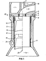
- Fig. 1 shows a cylinder tube 13 which is expediently embedded in an engine housing 12 with a press fit and is supported on the engine housing 12 at the end facing the crankcase 14.
- annular cooling space 9 is arranged, which is open to the cylinder head 16 and there has a liquid inflow formed as an annular groove 7, while the liquid outflow 11 is formed by a slot between the cylinder tube and the motor housing, which is formed by the support 24 of the cylinder tube on the engine housing leads to the crankcase 14.
- the cylinder tube wall is thinner below the support 24 in the direction of the crankcase 14 than above the support. The difference is just the thickness of the cylinder tube with which it is supported on the motor housing.
- Cooling fins 10 are arranged on the outer wall of the cylinder tube, said cooling fins completely projecting through the cooling space 9 in the radial direction and resting radially on the motor housing 12. These cooling fins transmit the ignition pressure to the engine housing during the combustion process.
- the cylinder tube alone, without the cooling fins, is so thin-walled that it cannot withstand the ignition pressure in the radial direction, but very well the axially acting sealing force of the cylinder head 16.
- the cylinder tube is supported on the motor housing. It may be expedient for the support width equal to the K ühlrippenbreite. During installation, the thin-walled cylinder tube with its cooling fins is inserted into the engine housing from the cylinder head side.
- the cylinder tube is honed only after it has been shrunk into the motor housing 12. If the entire wall thickness of the cylinder tube with the cooling fins is supported on the motor housing, the cylinder tube and motor housing are machined together during honing.
- cylinder head 16 Above the cylinder tube and the engine housing is the cylinder head 16, which is seated on the engine housing.
- the seal between cylinder head 16 and cylinder tube 13 is achieved by metallic contact of the parts to be sealed with a slight protrusion of the cylinder tube.
- the oil seal to the outside is done by a seal 8.
- an exhaust valve (not shown) with its valve seat 4 and a bore for the valve stem 2 is arranged in the cylinder head 16.
- An outlet duct 3 leads from the valve seat 4 to the edge of the cylinder head 16. Two spaces 1, in which coolant is conducted, surround the outlet duct 3.
- Channels 5 are arranged in the cylinder head base 25, which lead from the outside of the cylinder head to the valve seat 4. These channels 5 are sealed to the outside by a plug 6. Above the annular cooling space 9 in the cylinder tube, which is open towards the cylinder head, there is an annular groove 7 open towards the cooling space in the cylinder head. This annular groove is in fluid connection with the channels 5 at four points through inlet openings 17, which result from the intersections of the channels 5 with the annular groove 7 (see description of FIGS. 3 to 6).
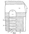
- FIG. 2 shows an enlarged detail of the cylinder head base 25 with the channel 5 and the annular groove 7, which is arranged above the cooling chamber 9 in the cylinder head 16 and the cooling fins 10 located in the cylinder tube.
- the channel 5 is liquid-carrying at four points by means of inlet openings 17 the annular groove 7 connected, which in turn is open to the cooling chamber 9.
- the cooling fins of the cylinder tube are arranged in the cooling chamber. These project completely through the cooling space and lie radially on the motor housing 12 and have liquid passages 19.
- cooling fins are dimensioned such that the temperature of the outside of the cylinder tube up to the cooling fin tip 22 is reduced approximately to the temperature of the cooling liquid.
- FIG. 3 shows a plan view of a cylinder tube with cooling fins seen in the axial direction
- FIG. 4 shows a section through this cylinder tube along the line IV-IV in FIG. 3
- Fig. 5 shows a section along the line VV in Fig. 3
- Fig. 6 shows a development of this cylinder tube with part of the adjacent cylinder head.
- the inlet openings 17 are provided at four locations evenly distributed over the circumference. It can also be expedient to provide more or fewer inlet openings.
- the uppermost cooling fin facing the cylinder head has four liquid passages that lie between the inlet openings. If a different number E inlingersöffnun- gene is present, then also the number of fluid passages in the uppermost cooling fin accordingly much so that always a fluid passage is disposed between the inlet openings and such. These liquid passages extend axially up to a section of the cooling space which is filled with liquid-impermeable, pressure-resistant material 20.
- cooling ribs only one section of the cylinder tube facing the cylinder head is provided with cooling ribs, while in the other section, liquid-impermeable, pressure-resistant material 20 is arranged except for cooling channels 18 running in the axial direction. In addition to those just described, there are four more cooling channels 18. These remaining four cooling channels also pass through the material 20 and the cooling fins except for the uppermost cooling fins and are located approximately below the inlet openings 17.
- the liquid passages 19 are arranged so that there is a labyrinthine path for the liquid. It also makes sense if the liquid passages in all cooling fin levels are congruent with each other with respect to the cylinder tube axis 23.
- the uppermost cooling fin located in this area has fewer liquid passages than the cooling fins of the other levels.
- the coolant flows from the channels 5 in the cylinder head 16 via the inlet openings 17 into the annular groove 7, which is open to the annular cooling space 9 in the cylinder tube 13. From there, the coolant flows through the disposed between the inlet openings liquid passages 19 of the top K ühlrippe and 14, then either through one of the located below the inlet openings 17 axial cooling channels 18 or through a inlingersöff- voltages between the E arranged axial cooling channels in the direction crankcase If the cooling liquid reaches the section of the cylinder tube which is not provided with cooling fins 10, but with liquid-impermeable, pressure-resistant material 20, so it flows through the axially extending cooling channels which pass through this material 20 and which are arranged axially below the inlet openings 17 the F lüsstechniksabfluß into the crankcase housing 14. 11
Landscapes
- Engineering & Computer Science (AREA)
- Chemical & Material Sciences (AREA)
- Combustion & Propulsion (AREA)
- Mechanical Engineering (AREA)
- General Engineering & Computer Science (AREA)
- Cylinder Crankcases Of Internal Combustion Engines (AREA)
Applications Claiming Priority (2)
| Application Number | Priority Date | Filing Date | Title |
|---|---|---|---|
| DE19853521789 DE3521789A1 (de) | 1985-06-19 | 1985-06-19 | Fluessigkeitsgekuehltes zylinderrohr |
| DE3521789 | 1985-06-19 |
Publications (3)
| Publication Number | Publication Date |
|---|---|
| EP0206184A2 true EP0206184A2 (fr) | 1986-12-30 |
| EP0206184A3 EP0206184A3 (en) | 1988-01-13 |
| EP0206184B1 EP0206184B1 (fr) | 1990-10-03 |
Family
ID=6273552
Family Applications (1)
| Application Number | Title | Priority Date | Filing Date |
|---|---|---|---|
| EP86108150A Expired - Lifetime EP0206184B1 (fr) | 1985-06-19 | 1986-06-14 | Fourreau cylindrique refroidi par eau |
Country Status (2)
| Country | Link |
|---|---|
| EP (1) | EP0206184B1 (fr) |
| DE (2) | DE3521789A1 (fr) |
Cited By (4)
| Publication number | Priority date | Publication date | Assignee | Title |
|---|---|---|---|---|
| US5402754A (en) * | 1992-12-30 | 1995-04-04 | Saab-Scania Ab | Wet cylinder liner |
| EP1227236B1 (fr) * | 2001-01-20 | 2006-07-19 | Bayerische Motoren Werke Aktiengesellschaft | Batiment moteur pour un moteur à pistons à combustion avec refroidissement par eau |
| US7765917B2 (en) | 2007-01-12 | 2010-08-03 | Black & Decker Inc. | Air compressor |
| GB2600240B (en) * | 2020-09-30 | 2024-03-06 | Caterpillar Inc | Liner for engine block and systems, assemblies, components, and methods thereof |
Families Citing this family (3)
| Publication number | Priority date | Publication date | Assignee | Title |
|---|---|---|---|---|
| DE3632160A1 (de) * | 1986-09-22 | 1988-03-31 | Kloeckner Humboldt Deutz Ag | Brennkraftmaschine |
| DE102005040635A1 (de) * | 2005-08-27 | 2007-03-01 | Deutz Ag | Wassergekühlte Brennkraftmaschine |
| DE102005040639A1 (de) * | 2005-08-27 | 2007-03-01 | Deutz Ag | Ölgekühlte Brennkraftmaschine |
Family Cites Families (8)
| Publication number | Priority date | Publication date | Assignee | Title |
|---|---|---|---|---|
| GB204106A (en) * | 1922-06-19 | 1923-09-19 | William Joseph Still | Improvements in the construction of internal combustion engine cylinders |
| US2078499A (en) * | 1928-09-01 | 1937-04-27 | Spontan Ab | Cooling system for internal combustion engines |
| US1904459A (en) * | 1929-08-21 | 1933-04-18 | Sulzer Ag | Cylinder for internal combustion engines |
| US2238404A (en) * | 1939-09-19 | 1941-04-15 | Spencer Aircraft Motors Inc | Internal combustion engine |
| FR1042296A (fr) * | 1950-09-22 | 1953-10-30 | Maschf Augsburg Nuernberg Ag | Moteur à combustion interne à refroidissement par liquide |
| DE1916096A1 (de) * | 1969-03-28 | 1970-10-08 | Daimler Benz Ag | Zylinderblock fuer fluessigkeitsgekuehlte Brennkraftmaschinen mit eingesetzter Zylinderlaufbuechse |
| NL7004500A (fr) * | 1970-03-28 | 1971-09-30 | ||
| DE2725059A1 (de) * | 1977-06-03 | 1978-12-14 | Kloeckner Humboldt Deutz Ag | Wassergekuehlte hubkolbenbrennkraftmaschine mit nassen zylinderlaufbuchsen |
-
1985
- 1985-06-19 DE DE19853521789 patent/DE3521789A1/de not_active Withdrawn
-
1986
- 1986-06-14 EP EP86108150A patent/EP0206184B1/fr not_active Expired - Lifetime
- 1986-06-14 DE DE8686108150T patent/DE3674647D1/de not_active Expired - Fee Related
Cited By (4)
| Publication number | Priority date | Publication date | Assignee | Title |
|---|---|---|---|---|
| US5402754A (en) * | 1992-12-30 | 1995-04-04 | Saab-Scania Ab | Wet cylinder liner |
| EP1227236B1 (fr) * | 2001-01-20 | 2006-07-19 | Bayerische Motoren Werke Aktiengesellschaft | Batiment moteur pour un moteur à pistons à combustion avec refroidissement par eau |
| US7765917B2 (en) | 2007-01-12 | 2010-08-03 | Black & Decker Inc. | Air compressor |
| GB2600240B (en) * | 2020-09-30 | 2024-03-06 | Caterpillar Inc | Liner for engine block and systems, assemblies, components, and methods thereof |
Also Published As
| Publication number | Publication date |
|---|---|
| DE3521789A1 (de) | 1987-01-02 |
| DE3674647D1 (de) | 1990-11-08 |
| EP0206184B1 (fr) | 1990-10-03 |
| EP0206184A3 (en) | 1988-01-13 |
Similar Documents
| Publication | Publication Date | Title |
|---|---|---|
| DE3032253C2 (de) | Verbrennungsmotor, insbesondere Dieselmotor | |
| DE3403624A1 (de) | Gebauter, fluessigkeitsgekuehlter kolben fuer brennkraftmaschinen | |
| DE2825298C2 (de) | Flüssigkeitsgekühlter Zylinderdeckel eines Viertakt-Dieselmotors | |
| DE3629672C2 (fr) | ||
| DE2236028A1 (de) | Zylinderkopf fuer eine wassergekuehlte brennkraftmaschine | |
| DE112007000918B4 (de) | Zylinderkopf für einen Motor sowie Motor | |
| DE3443085A1 (de) | Doppelrohr-waermetauscher | |
| DE2355292C2 (de) | Gekühltes Tellerventil einer Kolbenbrennkraftmaschine | |
| DE10221561A1 (de) | Gekühlter Kolben für einen Verbrennungsmotor | |
| DE3127122C2 (de) | Flüssigkeitsgekühlter Ventilsitz für ein Auslassventil einer Kolbenbrennkraftmaschine | |
| AT521945B1 (de) | Brennkraftmaschine mit einem Kühlflüssigkeitsmantel | |
| EP0206184B1 (fr) | Fourreau cylindrique refroidi par eau | |
| DE2755612C2 (de) | Flüssigkeitsgekühlter Zylinderdeckel für einen Viertakt-Dieselmotor | |
| DE3442488A1 (de) | Fluessigkeitsgekuehlte hubkolbenbrennkraftmaschine mit in reihe angeordneten zylindern | |
| EP0128435B1 (fr) | Culasse de cylindre pour un moteur à combustion interne | |
| DE2441689A1 (de) | Vorrichtung zur kuehlung von ventilen, insbesondere von auslassventilen fuer brennkraftmaschinen | |
| DE69102656T2 (de) | Zylinderlaufbüchse für eine wassergekühlte brennkraftmaschine. | |
| DE60127478T2 (de) | Zylinderkopf für eine Brennkraftmaschine | |
| EP0206125B1 (fr) | Culasse pour moteur à combustion interne à refroidissement par liquide | |
| DE2936630A1 (de) | Kolben fuer eine brennkraftmaschine | |
| DE19739165A1 (de) | Brennkraftmaschine mit direkt gekühlter Zylinderbüchse | |
| DE3601383A1 (de) | Kurbelgehaeuse mit eingegossenen kuehlraeumen | |
| DE19832844B4 (de) | Verbrennungsmotor mit einer auswechselbaren Zylinderlaufbuchse | |
| DE3528526A1 (de) | Hubkolbenbrennkraftmaschine | |
| DE10159100B4 (de) | Hubkolbenmaschine |
Legal Events
| Date | Code | Title | Description |
|---|---|---|---|
| PUAI | Public reference made under article 153(3) epc to a published international application that has entered the european phase |
Free format text: ORIGINAL CODE: 0009012 |
|
| AK | Designated contracting states |
Kind code of ref document: A2 Designated state(s): DE FR GB IT |
|
| PUAL | Search report despatched |
Free format text: ORIGINAL CODE: 0009013 |
|
| AK | Designated contracting states |
Kind code of ref document: A3 Designated state(s): DE FR GB IT |
|
| 17P | Request for examination filed |
Effective date: 19871219 |
|
| 17Q | First examination report despatched |
Effective date: 19890118 |
|
| GRAA | (expected) grant |
Free format text: ORIGINAL CODE: 0009210 |
|
| AK | Designated contracting states |
Kind code of ref document: B1 Designated state(s): DE FR GB IT |
|
| PG25 | Lapsed in a contracting state [announced via postgrant information from national office to epo] |
Ref country code: IT Free format text: LAPSE BECAUSE OF FAILURE TO SUBMIT A TRANSLATION OF THE DESCRIPTION OR TO PAY THE FEE WITHIN THE PRE;WARNING: LAPSES OF ITALIAN PATENTS WITH EFFECTIVE DATE BEFORE 2007 MAY HAVE OCCURRED AT ANY TIME BEFORE 2007. THE CORRECT EFFECTIVE DATE MAY BE DIFFERENT FROM THE ONE RECORDED.SCRIBED TIME-LIMIT Effective date: 19901003 Ref country code: FR Effective date: 19901003 Ref country code: GB Effective date: 19901003 |
|
| REF | Corresponds to: |
Ref document number: 3674647 Country of ref document: DE Date of ref document: 19901108 |
|
| EN | Fr: translation not filed | ||
| GBV | Gb: ep patent (uk) treated as always having been void in accordance with gb section 77(7)/1977 [no translation filed] | ||
| PLBE | No opposition filed within time limit |
Free format text: ORIGINAL CODE: 0009261 |
|
| STAA | Information on the status of an ep patent application or granted ep patent |
Free format text: STATUS: NO OPPOSITION FILED WITHIN TIME LIMIT |
|
| PGFP | Annual fee paid to national office [announced via postgrant information from national office to epo] |
Ref country code: DE Payment date: 19910823 Year of fee payment: 6 |
|
| 26N | No opposition filed | ||
| PG25 | Lapsed in a contracting state [announced via postgrant information from national office to epo] |
Ref country code: DE Effective date: 19930302 |