EP0206357A2 - Druckluftanlage für Nutzfahrzeuge - Google Patents
Druckluftanlage für Nutzfahrzeuge Download PDFInfo
- Publication number
- EP0206357A2 EP0206357A2 EP86108847A EP86108847A EP0206357A2 EP 0206357 A2 EP0206357 A2 EP 0206357A2 EP 86108847 A EP86108847 A EP 86108847A EP 86108847 A EP86108847 A EP 86108847A EP 0206357 A2 EP0206357 A2 EP 0206357A2
- Authority
- EP
- European Patent Office
- Prior art keywords
- compressed air
- exhaust air
- exhaust
- air
- compressed
- Prior art date
- Legal status (The legal status is an assumption and is not a legal conclusion. Google has not performed a legal analysis and makes no representation as to the accuracy of the status listed.)
- Ceased
Links
Images

Classifications
-
- F—MECHANICAL ENGINEERING; LIGHTING; HEATING; WEAPONS; BLASTING
- F01—MACHINES OR ENGINES IN GENERAL; ENGINE PLANTS IN GENERAL; STEAM ENGINES
- F01N—GAS-FLOW SILENCERS OR EXHAUST APPARATUS FOR MACHINES OR ENGINES IN GENERAL; GAS-FLOW SILENCERS OR EXHAUST APPARATUS FOR INTERNAL-COMBUSTION ENGINES
- F01N13/00—Exhaust or silencing apparatus characterised by constructional features
- F01N13/08—Other arrangements or adaptations of exhaust conduits
-
- B—PERFORMING OPERATIONS; TRANSPORTING
- B60—VEHICLES IN GENERAL
- B60T—VEHICLE BRAKE CONTROL SYSTEMS OR PARTS THEREOF; BRAKE CONTROL SYSTEMS OR PARTS THEREOF, IN GENERAL; ARRANGEMENT OF BRAKING ELEMENTS ON VEHICLES IN GENERAL; PORTABLE DEVICES FOR PREVENTING UNWANTED MOVEMENT OF VEHICLES; VEHICLE MODIFICATIONS TO FACILITATE COOLING OF BRAKES
- B60T17/00—Component parts, details, or accessories of power brake systems not covered by groups B60T8/00, B60T13/00 or B60T15/00, or presenting other characteristic features
- B60T17/002—Air treatment devices
- B60T17/008—Silencer devices
-
- F—MECHANICAL ENGINEERING; LIGHTING; HEATING; WEAPONS; BLASTING
- F01—MACHINES OR ENGINES IN GENERAL; ENGINE PLANTS IN GENERAL; STEAM ENGINES
- F01N—GAS-FLOW SILENCERS OR EXHAUST APPARATUS FOR MACHINES OR ENGINES IN GENERAL; GAS-FLOW SILENCERS OR EXHAUST APPARATUS FOR INTERNAL-COMBUSTION ENGINES
- F01N1/00—Silencing apparatus characterised by method of silencing
- F01N1/14—Silencing apparatus characterised by method of silencing by adding air to exhaust gases
-
- F—MECHANICAL ENGINEERING; LIGHTING; HEATING; WEAPONS; BLASTING
- F02—COMBUSTION ENGINES; HOT-GAS OR COMBUSTION-PRODUCT ENGINE PLANTS
- F02B—INTERNAL-COMBUSTION PISTON ENGINES; COMBUSTION ENGINES IN GENERAL
- F02B47/00—Methods of operating engines involving adding non-fuel substances or anti-knock agents to combustion air, fuel, or fuel-air mixtures of engines
-
- Y—GENERAL TAGGING OF NEW TECHNOLOGICAL DEVELOPMENTS; GENERAL TAGGING OF CROSS-SECTIONAL TECHNOLOGIES SPANNING OVER SEVERAL SECTIONS OF THE IPC; TECHNICAL SUBJECTS COVERED BY FORMER USPC CROSS-REFERENCE ART COLLECTIONS [XRACs] AND DIGESTS
- Y02—TECHNOLOGIES OR APPLICATIONS FOR MITIGATION OR ADAPTATION AGAINST CLIMATE CHANGE
- Y02T—CLIMATE CHANGE MITIGATION TECHNOLOGIES RELATED TO TRANSPORTATION
- Y02T10/00—Road transport of goods or passengers
- Y02T10/10—Internal combustion engine [ICE] based vehicles
- Y02T10/12—Improving ICE efficiencies
Definitions
- the invention relates to a compressed air system for commercial vehicles which are driven by an internal combustion engine which is supplied with fresh air via a suction line, and in which the compressed air system has at least one compressed air unit which is provided with an exhaust air outlet serving for ventilation, and with means for damping the exhaust noise caused by the exhaust air.
- control valves In such compressed air systems, consumers, such as working cylinders, are aerated and vented via control valves.
- the control pressures are set by pressure regulators which vent from time to time to maintain constant pressures. When these compressed air units are vented, considerable noise is generated by the exhaust air flowing out.
- noise-reducing means are provided in a known compressed air system, which are arranged as silencers on the individual compressed air units. These silencers slow down the flow velocity of the exhaust air and thus reduce the noise, but increase the dynamic pressure in the compressed air unit and cause an extension of the ventilation times, which sometimes exceed the ge legally prescribed values.
- the oil mist that is always present in the exhaust air pollutes the environment.
- the invention has for its object to design the noise-damping means in a compressed air system of the type mentioned in such a way that noise reduction in accordance with the legal requirements is achieved with short ventilation times in conjunction with avoidance of oil mist emissions, and without complex additional devices.
- the exhaust air outlet of the compressed air unit opens onto the suction line of the internal combustion engine.
- the fresh air supply system which is always present absorbs the exhaust air from the compressed air units and thus also the oil mist which is produced in connection therewith.
- the small amount of exhaust air from the compressed air units in relation to the total air requirement of the internal combustion engine remains on the one hand without any effect on the engine behavior, also with regard to the oil content of the exhaust air, on the other hand blowing noises into the open as well as substantial pollution by the oil are avoided, since this is burned. Because of the large air throughput of the engine, an air back pressure is also excluded, so that the specific ventilation sides of the compressed air units are not impaired.
- suction system according to the invention at the same time as a silencer and oil removal device for the compressed air units proves to be economically particularly advantageous since additional and complex separate silencers and / or oil removal devices can be dispensed with.
- the compressed air system 23 shown in the circuit diagram for a commercial vehicle has a plurality of compressed air units, each of which has an exhaust air outlet a serving for ventilation.
- Compressed air units of this type are a pressure regulator 11 connected downstream of a compressor 10 and connected on the output side to a protective valve 12, a dual-circuit brake valve 13 for controlling the brake cylinders ; Relay 18 and a trailer control valve 19. These compressed air units are connected to one another in a known manner in the manner shown in FIG.
- the exhaust air outlets of the compressed air units 11, 13, 14, 15, 18, 19, each designated a, are connected to a manifold 20.
- This manifold 20 should be on a large-volume silencer 21 in which an oil removal device, e.g. an oil filter or oil separator with an oil collector is integrated, to avoid noise pollution from the exhaust air flowing out and pollution of the environment from oil contained in the exhaust air.
- an oil removal device e.g. an oil filter or oil separator with an oil collector is integrated
- the fuel tank is designated 24, the engine block 25, the crankcase 26 and the injection pump 27.
- the fuel is conveyed to the injection pump 27 by means of a fuel feed pump 28 via a fuel filter 29.
- An injection line 30 leads from this to the injection nozzle 31 in the cylinder of the engine block 25.
- Combustion air is sucked in via a suction line 33 closed off with an air filter 32, while the combustion gases are discharged into the atmosphere via the exhaust system with the exhaust line 34 and the muffler 35.
- the manifold 20 of the compressed air system 23 is connected directly to the suction line 33, from which the exhaust air volumes of the compressed air units 11, 13, 14, 15, 18, 19 are taken up in FIG. 1 and fed to the engine for combustion.
Landscapes
- Engineering & Computer Science (AREA)
- Mechanical Engineering (AREA)
- Chemical & Material Sciences (AREA)
- Combustion & Propulsion (AREA)
- General Engineering & Computer Science (AREA)
- Transportation (AREA)
- Valves And Accessory Devices For Braking Systems (AREA)
- Exhaust Silencers (AREA)
- Compressors, Vaccum Pumps And Other Relevant Systems (AREA)
Abstract
Description
- Die Erfindung betrifft eine Druckluftanlage für Nutzfahrzeuge, die über einen Verbrennungsmotor angetrieben sind, der über eine Saugleitung mit Frischluft versorgt wird, und bei denen die Druckluftanlage mindestens ein Druckluftaggregat aufweist, das mit einem der Entlüftung dienenden Abluftausgang versehen ist, und mit Mitteln zur Dämpfung der durch die Abluft verursachten Ausströmgeräusche.
- Bei solchen Druckluftanlagen werden Verbraucher, wie Arbeitszylinder, über Steuerventile be- und entlüftet. Die Steuerdrücke werden von Druckreglern eingestellt, die zur Aufrechterhaltung von Konstantdrücken von Zeit zu Zeit entlüften. Beim Entlüften dieser Druckluftaggregate entstehen durch die ausströmende Abluft zum Teil erhebliche Geräusche.
- Zur Dämpfung dieser Geräusche sind-bei einer bekannten Druckluftanlage geräuschdämpfende Mittel vorgesehen, die als Schalldämpfer an den einzelnen Druckluftaggregaten angeordnet sind. Diese Schalldämpfer verlangsamen die Strömungsgeschwindigkeit der Abluft und vermindern damit die Geräuschentwicklung, erhöhen aber den Staudruck im Druckluftaggregat und bewirken eine Verlängerung der Entlüftungszeiten, die mitunter über den gesetzlich vorgeschriebenen Werten liegen. Außerdem wird durch den in der Abluft immer vorhandenen Ölnebel die Umwelt verschmutzt.
- Für Schalldämpfer an Luftauslässen von Druckluftaggregaten ist es deshalb auch schon bekannt, diese mit einer Ölabscheidevorrichtung zu kombinieren (DE-OS 30 01 486).
- Der Erfindung liegt die Aufgabe zugrunde, bei einer Druckluftanlage der eingangs genannten Art die geräuschdämpfenden Mittel so auszugestalten, daß eine den gesetzlichen Vorschriften entsprechende Geräuschdämpfung bei kurzen Entlüftungszeiten in Verbindung mit einer Vermeidung von Ölnebelausstoß erreicht wird, und zwar ohne aufwendige Zusatzeinrichtungen.
- Gemäß der Erfindung wird dies dadurch erreicht, daß der Abluftausgang des Druckluftaggregates auf die Saugleitung des Verbrennungsmotores ausmündet. Es nimmt somit bei der erfindungsgemäßen Lösung das stets vorhandene Frischluftversorgungssystem die Abluft der Druckluftaggregate und damit auch den in Verbindung hiermit anfallenden Ölnebel auf. Die in Bezug auf den Gesamtluftbedarf des Verbrennungsmotores geringe Abluftmenge der Druckluftaggregate bleibt einerseits ohne Auswirkung auf das Motorverhalten, auch bezüglich des Ölgehaltes der Abluft, andererseits sind Blasgeräusche ins Freie ebenso wie eine wesentliche Verschmutzung durch das Öl vermieden, da dieses verbrannt wird. Wegen des großen Luftdurchsatzes des Motores ist ferner ein Luftrückstau ausgeschlossen, so daß die spezifischen Entlüftungsseiten der Druckluftaggregate nicht beeinträchtigt werden.
- In Ausgestaltung der Erfindung ist es von Vorteil, wenn bei mehreren Druckluftaggregaten deren Abluftausgänge über eine Sammelleitung an die Saugleitung angeschlossen werden.
- Die erfindungsgemäße Nutzung des Saugsystems zugleich als Schalldämpfer und Entölvorrichtung für die Druckluftaggregate erweist sich wirtschaftlich als besonders günstig, da so auf zusätzliche und aufwendige gesonderte Schalldämpfer und/oder Entölvorrichtungen verzichtet werden kann.
- Die Erfindung ist anhand von in der Zeichnung dargestellten Ausführungsbeispielen im folgenden näher beschrieben. Es zeigen:
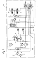
- Figur 1 ein Blockschaltbild einer Druckluftanlage für ein Nutzfahrzeug,
- Figur 2 eine schematische Darstellung eines Verbrennungsmotors in der Verbindung mit der Druckluftanlage in Figur 1.
- Die in Figur 1 im Schaltbild dargestellte Druckluftanlage 23 für ein Nutzfahrzeug weist eine Mehrzahl von Druckluftaggregaten auf, die jeweils einen der Entlüftung dienenden Abluftausgang a besitzen. Solche Druckluftaggregate sind ein einem Verdichter 10 nachgeschalteter Druckregler 11, der ausgangsseitig mit einem Schutzventil 12 verbunden ist, ein Zweikreis-Bremsventil 13 zur Steuerung der Bremszylinder,;Ein Handbremsventil 14, ein Relaisventil-15 für zwei Federspeicher 16, 17, ein Bremskraftregler-Relais 18 und ein Anhänger Steuerventil 19. Diese Druckluftaggregate sind in bekannter Weise in der in Figur 1 dargestellten Weise miteinander verbunden.
- Die mit a jeweils bezeichneten Abluftausgänge der Druckluftaggregate 11, 13, 14, 15, 18, 19 sind an eine Sammelleitung 20 angeschlossen. Diese Sammelleitung 20 sollte auf einen möglichst großvolumigen Schalldämpfer 21, in welchem eine Entölvorrichtung, z.B. ein Ölfilter oder Ölabscheider mit Ölsammler integriert ist, ausmünden, um Geräuschbelästigungen durch die abströmende Abluft und Verunreinigungen der Umwelt durch in der Abluft enthaltenes Öl zu vermeiden.
- Im Rahmen der Erfindung wird der gleiche Effekt in Verbindung mit dem Verbrennungsmotor 22 eines Nutzfahrzeuges unter Vermeidung eines gesonderten Schalldämpfers,wie in Fig. 2 geschildert, erreicht
- Von dem schematisch gezeigten Verbrennungsmotor 22 sind der Kraftstoffbehälter mit 24, der Motorblock mit 25, das Kurbelgehäuse mit 26 und die Einspritzpumpe mit 27 bezeichnet. Der Kraftstoff wird mittels einer Kraftstofförderpumpe 28 über ein Kraftstofffilter 29 zu der Einspritzpumpe 27 gefördert. Eine Einspritzleitung 30 führt von dieser zu der Einspritzdüse 31 im Zylinder des Motorblockes 25. Verbrennungsluft wird über eine mit einem Luftfilter 32 abgeschlossene Saugleitung 33 angesaugt, während die Verbrennungsgase über das Abgassystem mit der Abgasleitung 34 und dem Auspufftopf 35 in die Atmosphäre abgeführt werden. Die Sammelleitung 20 der Druckluftanlage 23 ist unmittelbar an die Saugleitung 33 angeschlossen, von der die Abluftvolumina der Druckluftaggregate 11, 13, 14, 15, 18, 19 in Figur 1 aufgenommen und dem Motor zur.Verbrennung zugeführt werden.
- Bei der beschriebenen Druckluftanlage ist es nicht zwingend, daß alle Druckluftaggregate an die Sammelleitung 20 angeschlossen werden. In vielen Fällen genügt es zu einer ausreichenden Geräuschdämpfung, nur solche Druckluftaggregate anzuschließen, die ein vorgegebenes Mindest-Abluftvolumen entlüften.
Claims (2)
dadurch gekennzeichnet ,
daß der Abluftausgang (a) des Druckluftaggregates (11, 13, 14, 15, 18, 19) auf die Saugleitung (33) des Verbrennungsmotores (22) ausmündet.
dadurch gekennzeichnet ,
daß die Abluftausgänge (a) mehrerer Druckluftaggregate (11, 13, 14, 15, 18, 19) über eine Sammelleitung (20) an die Saugleitung angeschlossen sind.
Applications Claiming Priority (2)
| Application Number | Priority Date | Filing Date | Title |
|---|---|---|---|
| DE19853523094 DE3523094A1 (de) | 1985-06-28 | 1985-06-28 | Druckluftanlage fuer nutzfahrzeuge |
| DE3523094 | 1985-06-28 |
Publications (2)
| Publication Number | Publication Date |
|---|---|
| EP0206357A2 true EP0206357A2 (de) | 1986-12-30 |
| EP0206357A3 EP0206357A3 (de) | 1987-04-29 |
Family
ID=6274393
Family Applications (2)
| Application Number | Title | Priority Date | Filing Date |
|---|---|---|---|
| EP86108838A Withdrawn EP0206356A3 (de) | 1985-06-28 | 1986-06-28 | Druckluftanlage für Nutzfahrzeuge |
| EP86108847A Ceased EP0206357A3 (de) | 1985-06-28 | 1986-06-28 | Druckluftanlage für Nutzfahrzeuge |
Family Applications Before (1)
| Application Number | Title | Priority Date | Filing Date |
|---|---|---|---|
| EP86108838A Withdrawn EP0206356A3 (de) | 1985-06-28 | 1986-06-28 | Druckluftanlage für Nutzfahrzeuge |
Country Status (2)
| Country | Link |
|---|---|
| EP (2) | EP0206356A3 (de) |
| DE (1) | DE3523094A1 (de) |
Families Citing this family (3)
| Publication number | Priority date | Publication date | Assignee | Title |
|---|---|---|---|---|
| DE19945704A1 (de) * | 1999-09-23 | 2001-04-12 | Knorr Bremse Systeme | Verfahren zur Steuerung eines Bremsvorgangs und fluidgesteuerte Fahrzeugbremse |
| DE102005053356B4 (de) * | 2004-11-27 | 2016-03-03 | Tenneco Gmbh | Vorrichtung zum Reduzieren des Abblasgeräusches von unter Druck stehenden Gasen |
| CN108860127B (zh) * | 2018-06-05 | 2020-06-26 | 北京汽车股份有限公司 | 制动系统排气工具 |
Family Cites Families (8)
| Publication number | Priority date | Publication date | Assignee | Title |
|---|---|---|---|---|
| BE452913A (de) * | ||||
| DE737548C (de) * | 1942-07-28 | 1943-07-17 | Teves Kg Alfred | Druckmittelbremsvorrichtung, insbesondere fuer Kraftfahrzeuge |
| FR1400458A (fr) * | 1964-04-13 | 1965-05-28 | Cie Generale D Entpr S Automob | Procédé d'amortissement du bruit d'échappement de l'air des freins pneumatiques de véhicules automobiles |
| US3845840A (en) * | 1973-06-04 | 1974-11-05 | Master Pneumatic Detroit | Silencer and lubricant trap for air tool exhaust |
| US3950946A (en) * | 1974-05-23 | 1976-04-20 | Toyota Jidosha Kogyo Kabushiki Kaisha | Vacuum producing system |
| SE415791B (sv) * | 1979-01-29 | 1980-10-27 | Gunnar Valdemar Eriksson | Kombinerad ljuddempare och oljefella for tryckluftapparater |
| DE3326802C2 (de) * | 1983-07-26 | 1986-03-20 | Festo KG, 7300 Esslingen | Anschlußblock |
| DE3334701A1 (de) * | 1983-09-24 | 1985-04-04 | Iveco Magirus AG, 7900 Ulm | Druckluftsystem eines motorfahrzeugs |
-
1985
- 1985-06-28 DE DE19853523094 patent/DE3523094A1/de not_active Withdrawn
-
1986
- 1986-06-28 EP EP86108838A patent/EP0206356A3/de not_active Withdrawn
- 1986-06-28 EP EP86108847A patent/EP0206357A3/de not_active Ceased
Also Published As
| Publication number | Publication date |
|---|---|
| EP0206356A3 (de) | 1987-04-15 |
| DE3523094A1 (de) | 1987-01-08 |
| EP0206356A2 (de) | 1986-12-30 |
| EP0206357A3 (de) | 1987-04-29 |
Similar Documents
| Publication | Publication Date | Title |
|---|---|---|
| DE2103705C3 (de) | ||
| DE102011084539B3 (de) | Turbolader mit einer Venturidüse zur Entlüftung eines Aktivkohlefilters | |
| EP1065350A2 (de) | Brennkraftmaschine mit einer Entlüftungseinrichtung | |
| DE102006041213A1 (de) | Einrichtung zur Kurbelraumentlüftung | |
| DE10154666A1 (de) | Kurbelgehäuseentlüftung für eine Brennkraftmaschine mit Abgasturboaufladung | |
| WO2006050812A1 (de) | Vorrichtung zur entlüftung eines kurbelgehäuses einer aufgeladenen brennkraftmaschine | |
| DE202005003462U1 (de) | Durchlüftungsanordnung für das Kurbelgehäuse einer Brennkraftmaschine | |
| DE3043018A1 (de) | Teilbetriebs-brennkraftmaschine | |
| EP0206357A2 (de) | Druckluftanlage für Nutzfahrzeuge | |
| DE19621936C2 (de) | Ölkreislauf in einem Verbrennungsmotor | |
| DE3546496A1 (de) | Druckluftanlage fuer nutzfahrzeuge | |
| EP2949911B1 (de) | Ventilplatteneinrichtung, insbesondere für eine filtervorrichtung für ein kraftfahrzeug | |
| DE3441033A1 (de) | Vorrichtung zum behandeln der verbrennungsgase und verringern des kraftstoffverbrauchs bei verbrennungsmotoren | |
| EP0922850A2 (de) | Kraftstoffversorgungssystem | |
| DE102015007155A1 (de) | Unterdruckerzeugung im Kurbelgehäuse zur Partikelzahlreduzierung | |
| DE2833481A1 (de) | Verfahren und vorrichtung zur abgasreinigung und zur verbesserung der kraftstoffausnutzung bei verbrennungskraftmaschinen | |
| DE102013004249A1 (de) | Filtervorrichtung für ein Kraftfahrzeug | |
| DE19916172C2 (de) | Kolben-Nachverdichter | |
| DE102016114400A1 (de) | Ständige Frischluft-Kurbelgehäuseentlüftung | |
| DE10105555A1 (de) | Entlüftungsvorrichtung für ölbeladene Gase einer Brennkraftmaschine | |
| EP1630367A1 (de) | Verfahren zur Entlüftung eines Kurbelgehäuses einer Brennkraftmaschine und Brennkraftmaschine zur Durchführung eines derartigen Verfahrens | |
| DE3545666C2 (de) | ||
| DE2745133A1 (de) | Anlage zur versorgung einer verbrennungskraftmaschine mit ladeluft und/oder zur versorgung eines druckluftbehaelters mit druckluft | |
| DE102010009913A1 (de) | Verbrennungskraftmaschine | |
| DE112005001335T5 (de) | Kompressoreinlassdruck-Steuer- bzw.-Regelsystem |
Legal Events
| Date | Code | Title | Description |
|---|---|---|---|
| PUAI | Public reference made under article 153(3) epc to a published international application that has entered the european phase |
Free format text: ORIGINAL CODE: 0009012 |
|
| AK | Designated contracting states |
Kind code of ref document: A2 Designated state(s): CH FR GB IT LI SE |
|
| PUAL | Search report despatched |
Free format text: ORIGINAL CODE: 0009013 |
|
| AK | Designated contracting states |
Kind code of ref document: A3 Designated state(s): CH FR GB IT LI SE |
|
| 17P | Request for examination filed |
Effective date: 19870425 |
|
| STAA | Information on the status of an ep patent application or granted ep patent |
Free format text: STATUS: EXAMINATION IS IN PROGRESS |
|
| 17Q | First examination report despatched |
Effective date: 19871124 |
|
| 18R | Application refused |
Effective date: 19890408 |
|
| RIN1 | Information on inventor provided before grant (corrected) |
Inventor name: UNSER, KARL-HEINZ Inventor name: PORTH, DIETER, DIPL.-ING. Inventor name: HOFER, HERMANN, DIPL.-ING. Inventor name: SCHOLZ, HELMUT |