EP0206478A2 - Schlauchförmige Fluchtvorrichtung - Google Patents
Schlauchförmige Fluchtvorrichtung Download PDFInfo
- Publication number
- EP0206478A2 EP0206478A2 EP86303411A EP86303411A EP0206478A2 EP 0206478 A2 EP0206478 A2 EP 0206478A2 EP 86303411 A EP86303411 A EP 86303411A EP 86303411 A EP86303411 A EP 86303411A EP 0206478 A2 EP0206478 A2 EP 0206478A2
- Authority
- EP
- European Patent Office
- Prior art keywords
- attached
- tube
- leash
- opening
- building
- Prior art date
- Legal status (The legal status is an assumption and is not a legal conclusion. Google has not performed a legal analysis and makes no representation as to the accuracy of the status listed.)
- Granted
Links
- 125000006850 spacer group Chemical group 0.000 claims description 12
- 239000004677 Nylon Substances 0.000 claims description 4
- 229920001778 nylon Polymers 0.000 claims description 4
- 238000003780 insertion Methods 0.000 claims description 3
- 230000037431 insertion Effects 0.000 claims description 3
- 229910052751 metal Inorganic materials 0.000 claims description 2
- 239000002184 metal Substances 0.000 claims description 2
- 230000009970 fire resistant effect Effects 0.000 description 4
- 238000004873 anchoring Methods 0.000 description 2
- 238000013459 approach Methods 0.000 description 2
- 229910000831 Steel Inorganic materials 0.000 description 1
- 239000004411 aluminium Substances 0.000 description 1
- 229910052782 aluminium Inorganic materials 0.000 description 1
- XAGFODPZIPBFFR-UHFFFAOYSA-N aluminium Chemical compound [Al] XAGFODPZIPBFFR-UHFFFAOYSA-N 0.000 description 1
- 238000010276 construction Methods 0.000 description 1
- 230000006378 damage Effects 0.000 description 1
- 239000004744 fabric Substances 0.000 description 1
- 230000005484 gravity Effects 0.000 description 1
- 239000000463 material Substances 0.000 description 1
- 238000000034 method Methods 0.000 description 1
- 230000000717 retained effect Effects 0.000 description 1
- 239000000779 smoke Substances 0.000 description 1
- 239000010959 steel Substances 0.000 description 1
Images

Classifications
-
- A—HUMAN NECESSITIES
- A62—LIFE-SAVING; FIRE-FIGHTING
- A62B—DEVICES, APPARATUS OR METHODS FOR LIFE-SAVING
- A62B1/00—Devices for lowering persons from buildings or the like
- A62B1/20—Devices for lowering persons from buildings or the like by making use of sliding-ropes, sliding-poles or chutes, e.g. hoses, pipes, sliding-grooves, sliding-sheets
Definitions
- This invention reJales generally to escape apparatus for an individuars use in evacuating a multi-storey building.
- Conventional fire escapes have disadvantages. They are generally finite in number, e.g. one or two per floor in a given building, if provided at all, and fixed in place so that, if smoke and flame approach a lower part of such fire escape, it is useless to persons on floors above that lower part.
- US-A-4 240 520 discloses a fire escape tunnel for use in exiting high-rise buildings.
- the tunnel includes an extendable, accordian pleated tubing made of nylon or canvas fabric padded on its inner side, a ring at its upper end attachable to an escape opening of a building, a lower end of the tubing having a soft landing pad, and an exit doorway so a person sliding or being lowered down the tunnel can step out onto the ground at the exit.
- US-A-4 099 596 discloses apparatus including a normally-folded flexible tube with a landing pad at its lower end that unfolds to a vertical chute condition, the interior of the tube being slippery to provide against snagging and the like, the unfolded tube being formed with elastic restrictions at successive vertical levels that snub the descent of a person descending inside from free fall to an alleged safe speed.
- US-A-3 580 358 discloses a safety escape chute having a series of pliant tubular columns connected by resilient portions made of spiral mesh so that when a first escaper is in the chute his weight so deforms the spiral mesh resilient portions downwardly that a second escaper cannot pass therethrough and thus cannot collide with the first escaper at the bottom of the chute.
- the fire escape tube utilized in apparatus embodying this invention is basically as described and claimed in my prior US-A-4 398 621.
- An object of the present invention is to provide escape apparatus which overcomes at least some of the disadvantages of presently proposed and available apparatus.
- the apparatus serving for exiting the building through an opening in said building, the apparatus being characterized by an upper, support entry ring member, a mesh tube attached at its upper end to the upper support entry member. and a lower, exit-opening support ring member attached to the lower end of said mesh tube, said lower support ring member having a leash attached at one end thereto and having a snap-on hook affixed to said leash at its end opposite the end attached to said lower ring member, said building having permanently attached thereto adjacent said opening one end of an elongate flexible member extending from said building to the ground, said flexible member being permanently secured at its other end to ground anchor means.
- the upper and lower support rings and attached mesh tube and leash with snap-on hook are preferably contained in a movable cart, and the upper support ring is preferably permanently attached to this movable cart.
- the apparatus preferably has a cushioning pad affixed to the cart to cushion the exit of the user from the building opening.
- the apparatus preferably has a generally semi-circular spacer bar attached to the upper support ring and intertwined among the meshes of the mesh tube in such orientation that upon deployment of the tube the spacer bar is orientated at approximately 45° to the vertical, thereby providing an easily accessible entrance opening for the user.
- the ground anchor means preferably has affixed thereto, adjacent the cable connection, a spring loaded grasping latch means which grasps and holds the leash upon descent of the leash and lower support ring to the ground.
- the grasping latch means preferably has external grooves which can retain the' leash in the event that the leash misses the grasping mechanism of the grasping latch upon deployment of the tube and support.
- the openings in the mesh tube are large enough to permit finger insertion therein but small enough to prevent foot inse) ? tron ' therethrough, and preferably have a maximum dimension of about 5cm.
- the mesh tube preferably has an inside diameter sufficiently large so as not to restrict passage of a person escaping therethrough, so that an escaping person can control his rate of descent by grasping the mesh anywhere within the tube.
- the mesh tube preferably has an inside diameter in the range of about 9Qcm to about 120cm.
- the upper supporting entry member has a maximum outside dimension D and, when in use, the mesh tube extends through the opening of the building and downward to the ground, the opening having a maximum dimension d, wherein D is greater than d, the tube thereby being supported to permit a person do descend therethrough.
- the upper supporting entry member preferably is a metal ring having diameter D.
- the apparatus perferabfy has an opaque shield encircling at least a part of the upper portion thereof so as to prevent a person using the escape from seeing through the mesh upon entry into the escape.
- the mesh tube is preferably made of fire resistant nylon cord or fire resistant, elastic bungi cord.
- Escape apparatus comprising. a movable cart for storing and, when needed, moving the apparatus into position for deployment out of a building, the fire escape having an upper, supporting entry ring member and a mesh tube attached to this upper support member, the mesh tube being substantially longer that the building height from which escape is necessary, and a lower, exit-opening support ring member attached to the lower end of the mesh tube.
- the fire escape is folded into the cart.
- the building is provided with at least one opening through which the fire escape is to be deployed. To the building near this opening is permanently attached a guide wire which extends from the opening at a desired angle to the ground where it is permanently affixed to a rigid support on the ground.
- a leash means To the lower ring support member, one end of a leash means is attached, the leash means having a snap-on mechanism removably engageable to the guide wire attached to the other end.
- the cart When escape is necessary, the cart is moved to the opening, the lower support member is attached to the guide wire by means of the snap-on leash, the lower support member then slides down the guide wire and the fire escape tube is deployed.
- a latch mechanism affixed to the rigid ground support which is capable of receiving and latching the snap-on mechanism and affixing it to the ground support when the lower support member descends to the ground. Once deployed, the fire escape tube can be descended by a person or persons to escape a fire in said building.
- FIG. 1 shows the components of the upper portion of the apparatus according to the invention located in and on the building 2 having window-like opening 3.
- the components of the apparatus shown include the upper, larger entry support ring 4, preferably affixed by attachment means 18 to the frame 16 mounted on a movable cart 12 having wheels 14. Prior to use, this apparatus can be stored in a closet for convenience.
- Attached to upper ring 4 is mesh tube 6, the details of which are not shown for clarity, attached at its other end to lower support ring 8.
- the lower ring has lanyard or leash 28 attached thereto as shown having a snap-on hook means 30 attached to its other end.
- Cushion 26 is preferably affixed to upper support ring 4 to help prevent scrapes and injuries to persons escaping as a result of hitting the building 2.
- the mesh tube 6 has semi-circular spacer bar 20 woven through it at the longitudinal distance downwardly of said tube from said upper support ring such that, in use as shown, the spacer bar 20 pivots to an approximately 45° angle to the vertical formed with upper support ring 4 to provide a convenient, held-upon entrance for users.
- the attachment means 18 includes means for pivotally attaching the semi-circular spacer bar 20 to upper support ring 4.
- Guide wire or cable 22 is shown attached to the building 2 adjacent the opening 3 by permanent attachment means 24.
- the user has wheeled the cart 12 containing the fire escape chute apparatus to a position in front of building opening 3 and has set the cusion 26 in place and pivoted the spacer bar 20 into position as indicated by the arrow.
- Rg. 2 shows a rear elevation of cart 12 and support rings 4 and 8 and semi-circular spacer bar 20. Ring 4 and spacer bar 20 are affixed to frame 16 by means 18. Also shown are cushion 26 and leash 28 having attached snap-on hook 30 attached to ring 8 as shown. Details of netting 6 are omitted for clarity of presentation.
- Figs. 3-5 show the sequence of steps in deployment of the apparatus.
- the user is shown drawing the smaller, lower support ring 8 through the larger upper support ring 4 and under spacer bar 20.
- Snap-on hook 30, similar to the hook commonly found on pet leashes, is snapped onto cable 22 and is thereby firmly attached thereto. Deployment of the chute is now ready to proceed.
- Fig. 4 shows the initial stage of descent of lower support ring member 8 and mesh tube 6.
- the ring 8 slides down guide wire 22, held by means of snap-on ring 30, under the influence of gravity. As it descends, more and more mesh tube 6 is payed out from its folded condition in cart 12.
- Fig. 5 shows an overall elevation, partly broken away, of the fire escape apparatus in a partly deployed condition (phantom) and fully deployed with lower support ring 8 anchored to the ground.
- the lower support ring 8 and attached mesh tube 6 are descending rapidly as indicated by the arrow shown.
- the mesh tube 6 extends from opening 3, held there by upper support ring 4, downwardly as shown to the ground, being anchored there by means of ground anchor 32 which holds spring-loaded grasping latch means 42 which has received leash 28 and holds it fixedly in place.
- users can now safely descend from the building 2 to the ground in the event of a fire.
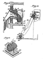
- Fig. 6 shows a side elevation of a portion of the ground anchoring means showing guide wire 22 affixed to ground anchor cross member 36 by means of bolt and eye 32 secured by nut 34 which permanently anchor cable 22.
- Spring-loaded grasping latch means 42 is shown affixed to ground anchor cross member 36 by means of bolt 40.
- the descending fire escape chute is shown approaching and then being grasped and retained by spring-loaded latch means 42 (in phantom).
- Fig. 7 shows a bottom plan view of the spring-loaded latch means having fingers, both denoted 42, spring-biased to the closed position by spring 50 held by pin 48.
- the fingers are spread apart as the leash enters the "V" formed by fingers 42 to accept the leash 28, after which the fingers 42 are closed by the spring bias 50 and they retain the leash 28 and the bottom support member 8 securely at ground level. If for some reason the leash 28 misses the "V" opening between fingers 42, e.g. due to wind, then external grooves 44 may catch the leash 28 and hold it at ground level.
- Fig. 8 shows a pictorial view of the lower end of the apparatus showing ground anchor bar 38 firmly and permanently mounted in foundation 46. Exit-opening support ring 8 is attached to the ground anchor by means of spring-loaded latch means grasping leash 28.
- the various support and frame members for example can be made from structurally sound aluminium or steel tubing.
- the mesh netting is preferably made of fire resistant nylon cord or fire resistant elastic bungi cord.
Landscapes
- Health & Medical Sciences (AREA)
- General Health & Medical Sciences (AREA)
- Business, Economics & Management (AREA)
- Emergency Management (AREA)
- Emergency Lowering Means (AREA)
- Farming Of Fish And Shellfish (AREA)
- Pipe Accessories (AREA)
- Surgical Instruments (AREA)
- Building Environments (AREA)
- Special Wing (AREA)
- Forms Removed On Construction Sites Or Auxiliary Members Thereof (AREA)
Priority Applications (1)
| Application Number | Priority Date | Filing Date | Title |
|---|---|---|---|
| AT86303411T ATE60910T1 (de) | 1985-05-24 | 1986-05-06 | Schlauchfoermige fluchtvorrichtung. |
Applications Claiming Priority (2)
| Application Number | Priority Date | Filing Date | Title |
|---|---|---|---|
| US06/738,042 US4582166A (en) | 1985-05-24 | 1985-05-24 | Fire escape having guide wire mechanism |
| US738042 | 1996-10-25 |
Publications (3)
| Publication Number | Publication Date |
|---|---|
| EP0206478A2 true EP0206478A2 (de) | 1986-12-30 |
| EP0206478A3 EP0206478A3 (en) | 1987-05-20 |
| EP0206478B1 EP0206478B1 (de) | 1991-02-20 |
Family
ID=24966329
Family Applications (1)
| Application Number | Title | Priority Date | Filing Date |
|---|---|---|---|
| EP86303411A Expired - Lifetime EP0206478B1 (de) | 1985-05-24 | 1986-05-06 | Schlauchförmige Fluchtvorrichtung |
Country Status (4)
| Country | Link |
|---|---|
| US (1) | US4582166A (de) |
| EP (1) | EP0206478B1 (de) |
| AT (1) | ATE60910T1 (de) |
| DE (1) | DE3677550D1 (de) |
Cited By (1)
| Publication number | Priority date | Publication date | Assignee | Title |
|---|---|---|---|---|
| EP3854679A1 (de) | 2020-01-24 | 2021-07-28 | Airbus Helicopters | Fahrzeug mit mindestens einem notausstiegssystem |
Families Citing this family (17)
| Publication number | Priority date | Publication date | Assignee | Title |
|---|---|---|---|---|
| US4582166A (en) * | 1985-05-24 | 1986-04-15 | Baker Safety Equipment, Inc. | Fire escape having guide wire mechanism |
| US4955605A (en) * | 1989-02-09 | 1990-09-11 | Goldfarb Adolph E | Home basketball apparatus |
| US5060753A (en) * | 1991-01-30 | 1991-10-29 | Sherlene Hopkins | Fire escape chute |
| US5562184A (en) * | 1995-07-11 | 1996-10-08 | Yung-Ho; Hsu | Apparatus for high-rise escape slow descending tube |
| CA2292024A1 (en) | 1999-12-07 | 2001-06-07 | David Lawrence Bockhold | Emergency passenger evacuation chute and chute/slide combination for aircraft |
| US6585081B1 (en) | 2002-01-25 | 2003-07-01 | Lynette J. Jerome | Fire escape device |
| US20030226713A1 (en) * | 2002-06-06 | 2003-12-11 | Ralph T. Baker | Fire escape |
| NO321073B1 (no) * | 2003-08-29 | 2006-03-13 | Viking Life Saving Equipment N | Anordning ved evakueringssystem |
| US20080156582A1 (en) * | 2007-01-03 | 2008-07-03 | Egbers Johannes H | Tall structure external emergency escape system |
| US20080283333A1 (en) * | 2007-05-17 | 2008-11-20 | Long Linda L | 911 Firejumper a movable strand descending and repelling device |
| US8708101B2 (en) * | 2012-02-17 | 2014-04-29 | David Patrick Bambrick | Life saving device for the home |
| US12049324B2 (en) | 2013-03-15 | 2024-07-30 | United Airlines, Inc. | Aircraft emergency escape slide container and method of changing an aircraft emergency escape slide |
| US9758251B2 (en) * | 2013-03-15 | 2017-09-12 | United Airlines, Inc. | Aircraft emergency escape slide container and method of changing an aircraft emergency escape slide |
| US10376798B2 (en) * | 2014-12-11 | 2019-08-13 | Buttercup Business, Inc. | High angle tethered slide with freefall drop and variable radius swing |
| KR101863901B1 (ko) * | 2017-08-30 | 2018-06-01 | 주식회사 에스엠텍 | 접이식 발코니 난간대 겸용 화재·재난 피난 시설 |
| CN107497068B (zh) * | 2017-10-11 | 2019-09-03 | 任维进 | 一种安全逃生系统 |
| NO348801B1 (en) * | 2023-05-12 | 2025-06-10 | Sævig Oeystein | Evacuation system |
Family Cites Families (10)
| Publication number | Priority date | Publication date | Assignee | Title |
|---|---|---|---|---|
| US2779596A (en) * | 1956-02-06 | 1957-01-29 | Herbert N Ridgway | Amusement slide |
| US3301347A (en) * | 1964-10-15 | 1967-01-31 | Saita Jisaburo | Lifesaving equipment to be used for structures |
| US3580358A (en) * | 1969-08-08 | 1971-05-25 | Masatada Yamamoto | Safety escape bag |
| GB1361178A (en) * | 1971-07-13 | 1974-07-24 | Car Mat Co Ltd | Emergency escape apparatus |
| US3826335A (en) * | 1973-02-01 | 1974-07-30 | M Allen | Personnel/load carrying system |
| US4099595A (en) * | 1976-04-20 | 1978-07-11 | Thomas Ray Tracy | Escape device |
| US4240520A (en) * | 1979-01-29 | 1980-12-23 | Lagrone Janet L | Hi rise escape tunnels and slide |
| US4339019A (en) * | 1980-04-07 | 1982-07-13 | Palladium Corporation | Safety chute |
| US4398621A (en) * | 1981-05-06 | 1983-08-16 | Baker Ralph T | Fire escape |
| US4582166A (en) * | 1985-05-24 | 1986-04-15 | Baker Safety Equipment, Inc. | Fire escape having guide wire mechanism |
-
1985
- 1985-05-24 US US06/738,042 patent/US4582166A/en not_active Expired - Lifetime
-
1986
- 1986-05-06 EP EP86303411A patent/EP0206478B1/de not_active Expired - Lifetime
- 1986-05-06 DE DE8686303411T patent/DE3677550D1/de not_active Expired - Lifetime
- 1986-05-06 AT AT86303411T patent/ATE60910T1/de not_active IP Right Cessation
Cited By (2)
| Publication number | Priority date | Publication date | Assignee | Title |
|---|---|---|---|---|
| EP3854679A1 (de) | 2020-01-24 | 2021-07-28 | Airbus Helicopters | Fahrzeug mit mindestens einem notausstiegssystem |
| US11603180B2 (en) | 2020-01-24 | 2023-03-14 | Airbus Helicopters Deutschland GmbH | Vehicle with at least one emergency exit system |
Also Published As
| Publication number | Publication date |
|---|---|
| US4582166A (en) | 1986-04-15 |
| EP0206478B1 (de) | 1991-02-20 |
| ATE60910T1 (de) | 1991-03-15 |
| EP0206478A3 (en) | 1987-05-20 |
| DE3677550D1 (de) | 1991-03-28 |
Similar Documents
| Publication | Publication Date | Title |
|---|---|---|
| EP0206478B1 (de) | Schlauchförmige Fluchtvorrichtung | |
| US4398621A (en) | Fire escape | |
| US4240520A (en) | Hi rise escape tunnels and slide | |
| US4161998A (en) | Fire escape device | |
| US9643034B2 (en) | Fall arrest system and lanyard | |
| US20080116007A1 (en) | Stowable, unobtrusive access and escape devices | |
| US4583616A (en) | Portable fire escape | |
| US6892857B2 (en) | Fire escape | |
| US4580659A (en) | Combination fire escape tube and rescue vehicle | |
| KR100923639B1 (ko) | 화재 피난용 안전 난간대 | |
| KR101913093B1 (ko) | 건물용 비상 탈출장치 | |
| CN1718258A (zh) | 滑梯式逃生和救生装置 | |
| RU2707894C1 (ru) | Устройство для самостоятельной эвакуации пассажиров с ограниченными возможностями из железнодорожных вагонов | |
| US6994182B2 (en) | Escape device for building | |
| WO2007106522A2 (en) | Access and escape devices | |
| US4452339A (en) | Emergency body descender | |
| JP4125236B2 (ja) | 高層ビル向き落下傘救助システム | |
| US5979601A (en) | Telescopic emergency egress device | |
| CA1179656A (en) | Fire escape | |
| US20090139797A1 (en) | Devices and methods for slowing descent | |
| US5871066A (en) | Rescue device | |
| KR20040076853A (ko) | 건물들, 드릴링 플랫폼들, 선박들 또는 그와 유사한 것과같은 구조물들로부터 사람들을 구조하기 위한 장치 | |
| CA1280099C (en) | Portable fire escape | |
| DE3019376A1 (de) | Abstandhalter | |
| CN117138267B (zh) | 用于建筑物火灾的集体逃生装置及逃生方法 |
Legal Events
| Date | Code | Title | Description |
|---|---|---|---|
| PUAI | Public reference made under article 153(3) epc to a published international application that has entered the european phase |
Free format text: ORIGINAL CODE: 0009012 |
|
| AK | Designated contracting states |
Kind code of ref document: A2 Designated state(s): AT BE CH DE FR GB IT LI LU NL SE |
|
| PUAL | Search report despatched |
Free format text: ORIGINAL CODE: 0009013 |
|
| AK | Designated contracting states |
Kind code of ref document: A3 Designated state(s): AT BE CH DE FR GB IT LI LU NL SE |
|
| 17P | Request for examination filed |
Effective date: 19871016 |
|
| 17Q | First examination report despatched |
Effective date: 19890608 |
|
| GRAA | (expected) grant |
Free format text: ORIGINAL CODE: 0009210 |
|
| AK | Designated contracting states |
Kind code of ref document: B1 Designated state(s): AT BE CH DE FR GB IT LI LU NL SE |
|
| PG25 | Lapsed in a contracting state [announced via postgrant information from national office to epo] |
Ref country code: IT Free format text: LAPSE BECAUSE OF FAILURE TO SUBMIT A TRANSLATION OF THE DESCRIPTION OR TO PAY THE FEE WITHIN THE PRESCRIBED TIME-LIMIT;WARNING: LAPSES OF ITALIAN PATENTS WITH EFFECTIVE DATE BEFORE 2007 MAY HAVE OCCURRED AT ANY TIME BEFORE 2007. THE CORRECT EFFECTIVE DATE MAY BE DIFFERENT FROM THE ONE RECORDED. Effective date: 19910220 Ref country code: CH Effective date: 19910220 Ref country code: AT Effective date: 19910220 Ref country code: BE Effective date: 19910220 Ref country code: NL Effective date: 19910220 Ref country code: SE Effective date: 19910220 Ref country code: FR Effective date: 19910220 Ref country code: LI Effective date: 19910220 |
|
| REF | Corresponds to: |
Ref document number: 60910 Country of ref document: AT Date of ref document: 19910315 Kind code of ref document: T |
|
| REF | Corresponds to: |
Ref document number: 3677550 Country of ref document: DE Date of ref document: 19910328 |
|
| PG25 | Lapsed in a contracting state [announced via postgrant information from national office to epo] |
Ref country code: LU Free format text: LAPSE BECAUSE OF NON-PAYMENT OF DUE FEES Effective date: 19910531 |
|
| REG | Reference to a national code |
Ref country code: CH Ref legal event code: PL |
|
| EN | Fr: translation not filed | ||
| NLV1 | Nl: lapsed or annulled due to failure to fulfill the requirements of art. 29p and 29m of the patents act | ||
| PLBE | No opposition filed within time limit |
Free format text: ORIGINAL CODE: 0009261 |
|
| STAA | Information on the status of an ep patent application or granted ep patent |
Free format text: STATUS: NO OPPOSITION FILED WITHIN TIME LIMIT |
|
| 26N | No opposition filed | ||
| PG25 | Lapsed in a contracting state [announced via postgrant information from national office to epo] |
Ref country code: DE Effective date: 19920303 |
|
| PGFP | Annual fee paid to national office [announced via postgrant information from national office to epo] |
Ref country code: GB Payment date: 19930428 Year of fee payment: 8 |
|
| PG25 | Lapsed in a contracting state [announced via postgrant information from national office to epo] |
Ref country code: GB Effective date: 19940506 |
|
| GBPC | Gb: european patent ceased through non-payment of renewal fee |
Effective date: 19940506 |