EP0206724A2 - Einrichtung mit Schlössern - Google Patents
Einrichtung mit Schlössern Download PDFInfo
- Publication number
- EP0206724A2 EP0206724A2 EP86304637A EP86304637A EP0206724A2 EP 0206724 A2 EP0206724 A2 EP 0206724A2 EP 86304637 A EP86304637 A EP 86304637A EP 86304637 A EP86304637 A EP 86304637A EP 0206724 A2 EP0206724 A2 EP 0206724A2
- Authority
- EP
- European Patent Office
- Prior art keywords
- lock
- closure member
- container
- hole
- aperture
- Prior art date
- Legal status (The legal status is an assumption and is not a legal conclusion. Google has not performed a legal analysis and makes no representation as to the accuracy of the status listed.)
- Withdrawn
Links
Images



Classifications
-
- E—FIXED CONSTRUCTIONS
- E05—LOCKS; KEYS; WINDOW OR DOOR FITTINGS; SAFES
- E05B—LOCKS; ACCESSORIES THEREFOR; HANDCUFFS
- E05B9/00—Lock casings or latch-mechanism casings ; Fastening locks or fasteners or parts thereof to the wing
- E05B9/08—Fastening locks or fasteners or parts thereof, e.g. the casings of latch-bolt locks or cylinder locks to the wing
Definitions
- This invention relates to an establishment with a plurality of locking systems and, more particularly, to locking systems in which the lock is removable from the safe or other security device.
- British Patent Application No. 8427022 discloses a safe suitable for installation in hotel rooms and the like including a container provided with a hinged door, a key hole in the door and a bracket on the interior surface of the door adapted removably to mount a lock for the safe, a key hole in the lock being located in register with the key hole in the door when the lock is mounted by the bracket.
- British Patent Application No. 8427022 requires the door of the safe to be open while the lock is being accommodated in the bracket which is on the inside face of the door, and requires the key to be removed from the lock because the key needs to approach the outside face of the door before being put in the key hole of the door and hence into the key hole of the lock. This can increase the likelihood of the key being lost. Also the arrangement disclosed in Specification No. 8427022 makes it necessary for the door of the safe to be in the open position while the lock is being accommodated in the bracket or removed therefrom.
- an establishment comprising a plurality of locking systems, each locking system comprising:
- the locking systems of the establishment of the present invention can take various different forms.
- a first form of locking system for an establishment in accordance with the present invention comprises:
- a second form of locking system for an establishment in accordance with the present invention comprises:
- a third form of locking system for an establishment in accordance with the present invention comprises:
- the closure member of the locking system of the establishment of the present invention may be a door which is pivotably mounted with respect to the container or may be a drawer which can be slid into and out of the container.
- the actuating means of the locking system of the establishment of the present invention may be in the form of a key which is removable from the lock or may e in the form of a combination system which remains permanently associated with the lock.
- the hole is preferably a slot, which is non-circular, so that a non-circular portion of the lock may fit into the slot and be prevented from rotation with respect thereto, whilst another portion of the lock, which is also non-circular, passes through the hole and, upon actuation of the lock, can be caused to engage the container or engage another member which engages the container.
- the lock of the second form of locking system can have a hole in the form of a non-circular slot provided at an edge region of the closure member, there being provision to prevent rotation of the lock with respect to the closure member.
- the pocket may be, but it is not necessarily, in the container and the arrangement may be such that, with the lock in the pocket, actuation of the lock causes one or more member to project from the lock so as to secure the lock within the pocket and also to secure the closure member with respect to the container.
- the actuating means for actuating the lock can be in such a position as to actuate the lock whilst the lock is being accommodated in the hole which is intended to receive it.
- This is in contrast to the arrangement disclosed in British Patent Application No. 8427022 and has the advantage that the actuating means, if it is to be separated for security reasons from the lock, does not need to be separated until the lock is in position in the hole and the lock has been actuated so as to cause the lock to be secured in its proper location and the closure member closed with respect to the container.
- the actuating means is a key which can be removed from the lock once the lock is in its correct position and has been actuated into the locking mode
- the relationship between the key and the lock can be such that with the lock in the unlocked mode the key cannot be withdrawn from the lock, and withdrawal of the key from the lock is possible only when the key has been turned to the appropriate position by which time the lock is in the locked mode.
- this provision reduces the likelihood of the loss of the key between, for example, the time that the lock and key are handed by the reception desk staff of a hotel to a guest and the time that the guest has put his valuables in a safe in his bedroom and locked the safe.
- part of the lock of the locking system of the establishment of the present invention may secure the lock with respect to the container or closure member and also to secure the closure member with respect to the container; alternatively, part of the lock, upon suitable actuation, may cause another element, such as a dead bolt, to achieve the locking between the closure member and the container. In this last-mentioned case the same part of the lock can secure the lock itself to the closure member or container.
- Figure 1 shows a lock generally indicated by reference numeral 1 and a key generally indicated by reference numeral 2.
- the key and lock are of a standard design, such as that made by Lowe & Fletcher Limited, of Bilston, West Midlands.
- the lock has an annular recess 3 for receiving the key, but in the illustrated embodiment the key can only be introduced into, and withdrawn from, the recess 3 when the key 2 is in one particular orientation with respect to the lock 1 by virtue of the projection 4 on the key 2 needing to cooperate with the cut-away 5 adjacent the annular recess 3.
- Figure 2 is similar to Figure 1 except that the key 2 is now inserted in the lock 1.
- lock cam 6 which is rotatable in response to actuation by the key 2.
- the lock cam 6 is elongate and corresponds to, but is slightly smaller than, a hole 7 through which the lock cam 6 may be passed.
- the lock cam 6 is not planar, and an intermediate region of the cam 6 is secured by a nut 8 to the lock spindle 9.
- a projection 10 Secured against rotation with respect to the main body of the lock 1 is a projection 10 which is non-circular and which has two parallel sides which can fit between the two parallel sides of the hole 7.
- the projection 10, when located in the hole 7, can prevent any rotation of the main body of the lock 1, whilst the lock cam 6 on the spindle 9 is free to rotate upon suitable actuation by the key 2.
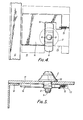
- FIG. 4 there are shown a hinged door 11 for closing an aperture of a container 12.
- a bracket 13 which serves as a guide for a dead bolt 14 which is urged to the right (in Figures 4 and 5) by the action of a tension spring 15.
- the dead bolt 14 has an abutment face 16, the arrangement being such that when the lock 1 is being fitted to the door 11, the cam 6 is vertically disposed as it passes through the vertically disposed hole 7 in the door.
- bracket 13 has only been shown in outline in Figures 4, 5 and 6 and has, for the sake of clarity, been omitted in Figure 7. A suitable general form of bracket is shown with regard to a later embodiment.
- the lock 21 is shown in situ in a hole (like the hole 7 in Figure 2) in a door 22.
- a bracket 23 shown most clearly in Figure 10.
- the bracket serves as a guide for the dead bolt 24 which can be moved to the left (in Figure 12) by the lock cam 25 against the action of springs 26.
- the bracket has a first raised portion 27 which is higher than a second raised portion 28. This is because the first raised portion needs to accommodate the innermost part of the lock 21, whereas the second portion 27 merely needs to accommodate the reciprocating dead bolt 24.
- the bracket 23 is also provided in the region of its first portion 27 with a hole 29 for accommodating the nut 30 and the rearmost portion of the spindle 31, and the bracket 23 is also provided with flanges 32 by which the bracket may be secured to the rear of the door 22.
- the lock generally indicated by the reference numeral 41 instead of being introduced into a hole away from the edge of the door, as is the case with the embodiments described in detail herein above, is introduced into a slot 42 provided in an edge region of the door 43.
- the slot 42 is generally rectangular in form as is also the rearmost part of the lock 41.
- the door 43 is secured between inner and outer flanges 44 and 45 provided on the lock 41. Whilst the door 43 is in the open position the lock 41 may be freely moved into and out of the slot 42. However, with the lock 41 fully in the slot 42, when the door 43 is closed, so as to close the container 46, the container 46 prevents removal of the lock 41 from the slot 42.
- Suitable actuation of the lock 41 causes a dead bolt 47 of the lock to project and to become positioned behind part of the container 46, as is shown in Figure 18, thereby preventing any relative movement between the door 43 and the container 46.
- a lock 51 is located in a door 52 which has a suitable hole 53. Located on the rear of the door 52 adjacent the hole 53 is a stop 54.
- the rear of the lock is generally circular in cross-section but is provided with three projections 55, only two of which are shown.
- the projections 55 can pass through corresponding cut-aways 56 adjacent the hole 53; that part of the lock bearing the projections 55 can be rotated so that the projections 55, instead of being opposite the cut-aways 56, are opposed to regions of the door adjacent the hole 53, thereby preventing withdrawal of the lock 51 from the door 52. Excess rotation of the projections 55 is prevented by means of the stop 54.
- Actuation of the lock 51 in addition to causing rotation of the component carrying the projections 55 also causes the projection from a rearmost part of the lock 51 of a dead bolt 57, which can then secure the door 52 (in which the lock 51 is securely located) to a container (not shown) to be closed by the door 52.
- the lock 51 illustrated in Figure 19 is of the type requiring actuation by a key and, as with other types of lock already described which require the use of a key, the lock, with the key in position, can be inserted into the hole 53, without the need for prior removal of the key.
- the lock of this particular locking system in accordance with the present invention is generally indicated by the reference numeral 61.
- the lock can be dropped into its correct position in spaced-apart pockets 62, 63 provided in an edge region of a container 64 having an aperture 65 to be closed by a door (not shown).
- Mounted on the front face of the lock 61 are buttons 66 carrying different indicia, in this case numerals, and visible on, and capable of projecting from, one side face of the lock 61 is a plurality of dead bolts 67.
- the hotel guest can drop the lock 61 into the pockets 62, 63, place his valuables in the safe, close the door of the safe, and then set a suitable combination on the lock 61 by pressing suitable buttons 66. Then when the lock is actuated the dead bolts 67 project from the lock 61 and engage in corresponding recesses in an edge region of the door (not shown). The projection of the dead bolts not only secures the door with respect to the container, but also prevents removal of the lock 61 from the container 64 and its associated pockets 62,63. Only by correctly pressing the right combination of buttons 66 are the dead bolts 67 caused to retreat into the lock 61, thereby freeing the door to be opened and thereby permitting the lock to be removed.
Landscapes
- Engineering & Computer Science (AREA)
- Mechanical Engineering (AREA)
- Closures For Containers (AREA)
Applications Claiming Priority (2)
| Application Number | Priority Date | Filing Date | Title |
|---|---|---|---|
| GB8515094 | 1985-06-14 | ||
| GB08515094A GB2176234A (en) | 1985-06-14 | 1985-06-14 | A portable locking system |
Publications (2)
| Publication Number | Publication Date |
|---|---|
| EP0206724A2 true EP0206724A2 (de) | 1986-12-30 |
| EP0206724A3 EP0206724A3 (de) | 1988-10-12 |
Family
ID=10580747
Family Applications (1)
| Application Number | Title | Priority Date | Filing Date |
|---|---|---|---|
| EP86304637A Withdrawn EP0206724A3 (de) | 1985-06-14 | 1986-06-16 | Einrichtung mit Schlössern |
Country Status (2)
| Country | Link |
|---|---|
| EP (1) | EP0206724A3 (de) |
| GB (1) | GB2176234A (de) |
Family Cites Families (11)
| Publication number | Priority date | Publication date | Assignee | Title |
|---|---|---|---|---|
| US1362514A (en) * | 1917-12-27 | 1920-12-14 | American Hardware Corp | Door and lock therefor |
| GB279287A (en) * | 1927-01-24 | 1927-10-27 | Kraemer Hermann | Locking device |
| GB374614A (en) * | 1931-05-29 | 1932-06-16 | Leon Hopeon Leapman | Improvements in or relating to door and like fastening means |
| GB690794A (en) * | 1951-10-05 | 1953-04-29 | Edouard Miney | Improvements in doors for safes and the like |
| GB1245832A (en) * | 1968-08-28 | 1971-09-08 | David Roy Parker | Means for preventing the theft of road wheels from vehicles |
| US3820283A (en) * | 1972-09-14 | 1974-06-28 | J Shramovich | Locking system and lock therefor |
| US3980329A (en) * | 1974-08-19 | 1976-09-14 | Loc-Coe | Manhole cover lock |
| GB1472261A (en) * | 1974-09-06 | 1977-05-04 | Weatherglaze Windows Ltd | Window glazing locking system |
| US4398405A (en) * | 1981-03-30 | 1983-08-16 | Product Concepts, Inc. | Lock with key-controlled removable and installable plug and key for same |
| GB2142967A (en) * | 1983-07-07 | 1985-01-30 | Europ Asian Consultants Inc | Safe |
| GB2148974A (en) * | 1983-10-25 | 1985-06-05 | Hilling Robert Harry | Safe with replaceable lock |
-
1985
- 1985-06-14 GB GB08515094A patent/GB2176234A/en not_active Withdrawn
-
1986
- 1986-06-16 EP EP86304637A patent/EP0206724A3/de not_active Withdrawn
Also Published As
| Publication number | Publication date |
|---|---|
| EP0206724A3 (de) | 1988-10-12 |
| GB2176234A (en) | 1986-12-17 |
| GB8515094D0 (en) | 1985-07-17 |
Similar Documents
| Publication | Publication Date | Title |
|---|---|---|
| US4576022A (en) | Object securing sleeve for padlock devices | |
| US5127244A (en) | Shackleless padlock | |
| US4055972A (en) | Combination-controlled and key-operated security padlock | |
| US4348967A (en) | Public security locker | |
| US4539828A (en) | Security lock box with removable key plug | |
| US6530248B1 (en) | Lock device | |
| US5425256A (en) | Door knob security device | |
| US4704880A (en) | Removable cam-lock unit and dead-bolt mechanism | |
| KR840008028A (ko) | 시정(施錠) 및 해정(解錠)장치 | |
| US3983728A (en) | Double changeable key lock for safe deposit boxes and the like | |
| US4462230A (en) | Changeable safe deposit lock with slidable clamped fences | |
| US4626007A (en) | Tilt bolt lock | |
| US3741619A (en) | Locking apparatus for vending machines or the like | |
| US5606880A (en) | Quick-release lock retaining bracket method and apparatus | |
| US6173593B1 (en) | Concealed locking mechanism and method for use with drawers or cabinet doors or the like | |
| US4320637A (en) | Key removable cylinder assembly from locket | |
| US2780087A (en) | Combination resetting guard for combination padlocks | |
| US3608341A (en) | Safety medicine chest | |
| GB2176234A (en) | A portable locking system | |
| US3273363A (en) | Combination changing dial, knob and escutcheon assembly | |
| US5005387A (en) | Cabinet locking device | |
| US3315622A (en) | Vault | |
| NO332947B1 (no) | Laseinnretning | |
| US3776008A (en) | Removable cylinder for a lockset | |
| US4922737A (en) | Lock arrangement |
Legal Events
| Date | Code | Title | Description |
|---|---|---|---|
| PUAI | Public reference made under article 153(3) epc to a published international application that has entered the european phase |
Free format text: ORIGINAL CODE: 0009012 |
|
| AK | Designated contracting states |
Kind code of ref document: A2 Designated state(s): AT BE CH DE FR GB IT LI LU NL SE |
|
| PUAL | Search report despatched |
Free format text: ORIGINAL CODE: 0009013 |
|
| AK | Designated contracting states |
Kind code of ref document: A3 Designated state(s): AT BE CH DE FR GB IT LI LU NL SE |
|
| STAA | Information on the status of an ep patent application or granted ep patent |
Free format text: STATUS: THE APPLICATION IS DEEMED TO BE WITHDRAWN |
|
| 18D | Application deemed to be withdrawn |
Effective date: 19890413 |