EP0206746A2 - Circuits pour modifier l'étendue de dynamique utilisant des circuits en série ou en parallèle - Google Patents
Circuits pour modifier l'étendue de dynamique utilisant des circuits en série ou en parallèle Download PDFInfo
- Publication number
- EP0206746A2 EP0206746A2 EP86304676A EP86304676A EP0206746A2 EP 0206746 A2 EP0206746 A2 EP 0206746A2 EP 86304676 A EP86304676 A EP 86304676A EP 86304676 A EP86304676 A EP 86304676A EP 0206746 A2 EP0206746 A2 EP 0206746A2
- Authority
- EP
- European Patent Office
- Prior art keywords
- band
- circuit
- frequency
- characteristic
- sliding
- Prior art date
- Legal status (The legal status is an assumption and is not a legal conclusion. Google has not performed a legal analysis and makes no representation as to the accuracy of the status listed.)
- Granted
Links
Images





Classifications
-
- H—ELECTRICITY
- H03—ELECTRONIC CIRCUITRY
- H03G—CONTROL OF AMPLIFICATION
- H03G7/00—Volume compression or expansion in amplifiers
-
- H—ELECTRICITY
- H03—ELECTRONIC CIRCUITRY
- H03G—CONTROL OF AMPLIFICATION
- H03G9/00—Combinations of two or more types of control, e.g. gain control and tone control
- H03G9/02—Combinations of two or more types of control, e.g. gain control and tone control in untuned amplifiers
- H03G9/025—Combinations of two or more types of control, e.g. gain control and tone control in untuned amplifiers frequency-dependent volume compression or expansion, e.g. multiple-band systems
Definitions
- the present invention is concerned in general with circuit arrangements which alter the dynamic range of signals, namely compressors which compress the dynamic range and expanders which expand the dynamic range. While the invention is useful for treating various types of signals, including audio signals and video (television) signals, the description of the invention is primarily in the context of the processing of audio signals. The principles of the invention may be applied to the processing of other signals by modifying the disclosed embodiments by applying known techniques. For example, compressors and expanders for video signals can act instantaneously and do not require syllabic control circuitry.
- Compressors and expanders are normally used together (a compander system) to effect noise reduction; the signal is compressed before transmission or recording and expanded after reception or playback from the transmission channel.
- compressors may be used alone to reduce the dynamic range, e.g., to suit the capacity of a transmission channel, without subsequent expansion when the compressed signal is adequate for the end purpose.
- compressors alone are used in certain products, especially audio products which are intended only to transmit or record compressed broadcast or pre-recorded signals.
- Expanders alone are used in certain products, especially audio products which are intended only to receive or play back already compressed broadcast or pre-recorded signals.
- a single device is often configured for switchable mode operation as a compressor to record signals and as an expander to play back compressed broadcast or pre-recorded signals.
- the spectrum is divided into a plurality of frequency bands, each of which is acted upon independently.
- a dominant signal component affects dynamic action (compression or expansion) only within a portion of the overall spectrum, in contrast to a wideband approach in which dynamic action throughout the entire spectrum is affected by a dominant signal component.
- a bandsplitting system provides a greater degree of adaptiveness or conformance than a wideband system.
- a highly adaptive or conformal system could be provided by dividing the overall spectrum into a very large number of frequency bands; however, the complexity and cost of such an arrangement makes it impractical. Consequently, a design compromise is made by selecting a reasonable number of frequency bands capable of providing satisfactory performance.
- a dominant signal component is a signal component having a substantial enough level so as to effect dynamic action within the frequency band under consideration. Under complex signal conditions there may be more than one dominant signal component or a dominant signal component and sub-dominant signal components. In a compander system which relies on complementarity of the compressor and expander, all of the signal components must be compressed and expanded in accordance with a defined compression/expansion law in order that the signal spectrum including the dominant signal component (and other signals affected by dynamic action) can be restored to their correct levels in the expander.
- a dominant signal component causes the cutoff or turnover frequency (or frequencies) of one or more variable filters (e.g., high pass, low pass, shelf, notch, etc.) to shift so as to compress or expand the dominant signal component.
- variable filters e.g., high pass, low pass, shelf, notch, etc.
- a sliding band system operating only in a single high frequency band is described in US-PS Re 28,426 and US-PS 4,490,691.
- This system which forms the basis for the well known consumer companding type audio noise reduction system known as B-type noise reduction, includes, in a dual path arrangement, a side path having a fixed high pass filter in series with a variable filter.
- a “dual path” arrangement is one in which a compression or expansion characteristic is achieved through the use of a main path which is essentially free of dynamic action and one or more secondary or side paths having dynamic action.
- the side path or paths take their input from the input or output of the main path and their output or outputs are additively or subtractively combined with the main path in order to provide compression or expansion.
- a side path provides a type of limiting or variable attenuation and the manner in which it is connected to the main path determines if it boosts (to provide compression) or bucks (to provide expansion) the main path signal components.
- Such dual path arrangements are described in detail in US-PS 3,846,719; US-PS 3,903,485; US-PS 4,490,691 and US-PS Re 28,426.
- a high frequency variable shelving filter in a single path arrangement (e.g., the dynamic action is accomplished in a single signal path) for a companding audio noise reduction system is set forth in US-PS 3,911,371.
- a dual path arrangement is set forth in which the side path comprises a variable shelving filter having an all-pass characteristic in its quiescent condition.
- Another approach for providing a variable shelving response for compander systems is set forth in US-PS 3,934,190.
- variable filter turnover frequency shifts to a frequency above that signal component thereby restricting the frequency area at lower frequencies in which noise reduction is provided.
- the loss of noise reduction may be more noticeable audibly than in bandsplitting systems and the related side effects (noise modulation and signal modulation) may be more severe than in fixed band arrangements because of a multiplication effect that is inherent in sliding band systems. This effect results from the way in which sliding band systems provide compression. If, for example, there is a dominant high frequency signal and 2 dB of gain reduction is required at that frequency, the variable filter cutoff frequency should shift to the extent necessary to provide that amount of attenuation along the filter slope.
- the effect may be 5 or 10 dB of dynamic action, for example, with a consequent loss of all or most of the noise reduction effect along with possible audible signal or noise modulation.
- a 2 dB change in a dominant signal can cause a 5 or 10 dB change in gain at frequencies removed from the dominant signal.
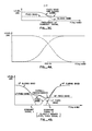
- Figure 1 is an idealized compressor characteristic rsponse curve illustrating this effect.
- an advantage of a sliding band arrangement is that the full noise reduction effect is obtained at frequencies above the dominant signal component (or below the dominant signal component in the case of a sliding band system acting downward in frequency).
- the advantage of fixed band is that there is no multiplication of modulation effects and the advantage of sliding band is that there is minimum signal or noise modulation above the dominant signal frequency
- the disadvantages of each e.g., the disadvantage of fixed band is noise and signal modulation throughout its operating range--although not multiplied and the disadvantage of sliding band is the mid-band modulation effect
- the present invention is based on the recognition that the ideal of conformal equalization can be more closely approached by compressor, expander and compander type noise reduction arrangements in which fixed band and sliding band characteristic actions operate within generally the same or overlapping frequency bands.
- such a result can be achieved by operating fixed band and sliding band circuit elements in parallel, either as parallel single path devices or as parallel side paths of a dual path arrangement.
- Such a result can also be achieved by operating such elements in a series arrangement, provided that relatively low compression ratios are used, so that the overall ratio (the product) does not exceed a value suitable for the signal channel.
- two series elements, each with a ratio of 1.5:1 would yield an overall ratio of 2.25, which is suitable for tape recorder channels. So that the effects of the series connected compressor elements occur in substantially the same dynamic region, the control amplifier gains should be lowered and/or the thresholds of the downstream elements should be raised in order to compensate for the signal gains produced by the upstream elements.
- the characteristics of the example of Figures 3A, 3B and 3C can be generated by a dual path arrangement having a main path and two side paths: a sliding band side path which has an all pass quiescent characteristic with a single pole high pass or low pass characteristic when active and a wide band fixed band side path. If each side path taken alone is assumed to provide 10 dB of action, then the effect of both side paths summed together is about 14.5 dB. The quiescent characteristic is thus a flat 14.5 dB wideband. Similar characteristics can be generated by two single side path dual path circuits in series, one circuit having a sliding band side path as just described and the other circuit having a wide band fixed band side path.
- An even more adaptive arrangement can be achieved according to this invention by providing a bandsplitting arrangement in which the high frequency band and low frequency band are each comprised of series or parallel fixed band/sliding band characteristic action elements.
- the sliding band acts upwardly in frequency while in the low frequency band the sliding band acts downwardly in frequency.
- the characteristics overlap so as to provide a flat overall characteristic.
- gentle filter slopes say, 6 dB/octave
- a common quiescent corner frequency in the middle of the frequency band say, 800 Hz for an audio system
- excellent tracking of a dominant signal by both the high and low frequency bands throughout a substantial portion of the band under processing is possible.
- the quiescent response of such an arrangement is shown in Figure 4A.
- the presence of two dominant signals results in a fixed band response between the dominant signals and sliding band response at frequencies above and below their frequencies where maximum noise reduction is most critical (Figure 4B).
- FIG. 5 shows a block diagram of a prior art sliding band circuit for processing audio signals which is usable in several ways: as a single path compressor (as shown), as a single path expander (by placing the circuit in the feed-back loop of an operational amplifier), as a side path of a dual path compressor, or as a side path of a dual path expander.
- Circuit details of a high frequency sliding band arrangement in accordance with the block diagram of Figure 5 are set forth in US-PS Re 28,426; US-PS 4,490,691; and US-PS 4,498,060.
- Figure 6 shows a block diagram of a prior art fixed band circuit for processing audio signals which is usable in the same ways as a compressor or expander either in a single path arrangement or in a side path of a dual path arrangement. Circuit details of fixed band arrangements in accordance with the block diagram of Figure 6 are set forth in US-PS 3,846,719; US-PS 3,903,485; and US-PS 4,498,060.
- the sliding band and fixed band circuit elements useful in the present invention are not limited to the processing of audio signals and include not only circuits of the type just mentioned, but also known modifications of such circuits, such as set forth in US-PS 4,490,691, and other known sliding band and fixed band circuits and their equivalents, including, for example, the sliding band arrangements of US-PS 3,846,719; US-PS 3,903,485; US-PS 3,911,371; US-PS 3,934,190; US-PS 4,306,201; US-PS 4,363,006; and US-PS 4,363,007, and the fixed band arrangements of US-PS 4,306,201 and US-PS 4,363,007.
- the cited patent specifications include details regarding the operation of such circuits as compressors and expanders in dual path arrangements and the operation of compressors as complementary expanders by placing them in the feedback loop of operational amplifiers.
- the sliding band circuit is shown having a fixed filter 2, a variable filter 4, an amplifier 6 the output of which is coupled to a non-linear limiter 8 for suppressing overshoots.
- the output of the overshoot suppression stage provides the circuit output and is also applied to a control circuit having an amplifier 10 the output of which is applied to a half-wave rectifier 12 and integrated by a smoothing filter 14 to provide a control signal for the variable filter 4.
- the fixed filter 2 may be implemented by a simple single pole RC filter.
- the variable filter 4 may also be implemented by a simple single pole RC filter in which the source-drain path of a field effect transistor (FET) is operated as a variable resistor by a control voltage applied to the FET gate.
- FET field effect transistor
- Figure 7 shows a fixed and variable filter arrangement for a high frequency sliding band circuit in which the cutoff frequency of the variable filter 4 moves upward in response to increasing control signal voltage level.
- Figure 8 shows a fixed and variable filter arrangement for a low frequency sliding band circuit in which the cutoff frequency of the variable filter 4 moves downward in response to increasing control signal voltage level.
- the fixed filter is defined by series capacitor 16 and shunt resistor 18 and the variable filter 4 is defined by the parallel arrangement of resistor 20 and capacitor 22 in series and the shunt FET 24 receiving the control. signal at its gate.
- Capacitor 16 and resistor 18 constitute a high pass filter
- resistor 20, capacitor 22 and FET 24 constitute a high pass shelving filter.
- resistor 20 can be omitted (changing variable filter 4 into a variable high pass filter), the inclusion of resistor 20 is useful in avoiding large phase shifts through the filters.
- the fixed filter is defined by series inductor 26 and shunt resistor 28 and the variable filter 4 is defined by the parallel arrangement of resistor 30 and inductor 32 in series and the shunt FET 24 receiving the control signal at its base.
- Inductor 26 and resistor 28 constitute a low pass filter
- resistor 30, inductor 32 and FET 24 constitute a low pass shelving filter.
- Resistor 30 serves the same purpose as does resistor 20 in the circuit of Figure 7.
- inductor 26 and resistor 28- would be replaced by a series resistor and shunt capacitor; non-grounded inductor 32 can be simulated by well known gyrator circuits employing operational amplifiers.
- the fixed filter 2 thus determines the frequency response of the circuit.
- the variable filter corner frequency rises and when it is above the corner frequency of the fixed filter it determines the frequency response of the circuit.
- the fixed filter 2 of the arrangements of Figures 5, 6, 7 and 8 can be omitted if desired, however, the additional sharpness of the overall filter characteristic that occurs when the variable filter corner frequency is near that of the fixed filter is a desirable characteristic.
- the amplifier 10 preferably includes frequency weighting in order to provide increased gain at high frequencies, in the case of a high frequency circuit, or at low frequencies, in the case of a low frequency circuit, in order that the circuit provides sufficient band narrowing (by sliding of the variable filter corner frequency) so as to create the necessary attenuation.
- the smoothing filter 14 provides the appropriate attack and decay time constants for treating audio signals (e.g., syllabic control).
- the fixed band circuit having a FET attenuator 36, an amplifier 38 the output of which is coupled to a non-linear Limiter 40 for suppressing overshoots.
- Amplifier 38 and limiter 40 are the same as amplifier 6 and limiter 8 of Figure 5.
- the output of the overshoot suppression stage provides the circuit output and is also applied to a control circuit having an amplifier 42 the output of which is applied to a phase splitter 44 which drives a full-wave rectifier 46 and is integrated by a smoothing filter 48.
- Full-wave rectification may also be employed in the sliding band arrangement of Figure 5 and alternatively, the half-wave rectification of
- Figure 5 may be employed in the fixed band arrangement of Figure 6.
- Full-wave rectification provides a more accurate control signal but at greater expense.
- the FET attenuator is configured as a simple voltage divider as shown in Figure 9.
- the source-drain path of the FET acts as a variable resistor in shunt with series resistor 52.
- the circuit thus provides wide band variable attenuation.
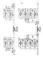
- Figure 10 shows one general arrangement of a compander system in accordance with the parallel aspect of the invention: a fixed band compressor 54 and a sliding band compressor 56 are connected in parallel, each receiving the same input and their respective outputs being combined in summing means 58 for application to a transmission channel.
- the transmission channel output is applied to a complementary expander in which the compressors 54 and 56 are in the feedback path of a high gain amplifier 60.
- Providing an expander by such an arrangement is well known.
- the frequency bands in which the respective fixed band and sliding band compressors operate is substantially the same or at least substantially overlapping.
- the range of signal levels at which the respective fixed band and sliding band compressors and expanders provide dynamic action is substantially the same: within a few decibels.
- the compressors may be any of the devices mentioned above.
- the voltage transfer function for a parallel arrangement of compressor or expander elements can be expressed by where Vin is the applied voltage, V out is the output voltage, and t (s), t 2 (s), etc. are the transfer functions of each parallel element.
- Vin is the applied voltage
- V out is the output voltage
- t (s), t 2 (s), etc. are the transfer functions of each parallel element. The transfer functions add together and each element operates independently.
- FIG 11 A more specific arrangement is shown in Figure 11, where the fixed band and sliding band circuits, such as those described in connection with Figures 5 through 9, are located in the side paths of a Type I dual path compander system (of the type generally described in US-PS 3,846,719).
- the arrangement has a compressor 66 in which the input signal is applied to the fixed band stage 68, to the sliding band stage 70, and to the main path 72.
- the outputs of stages 68 and 70 are combined in summing means 74 and then added to the main path signal components in summing means 76 to provide the compressor output for application to a transmission channel.
- the side path signal components thus boost the main path signal components causing compressor action.
- the transmission channel output is applied to the expander 78, configured in a complementary manner to the compressor 66.
- the expander 78 has an input summing means 80 which receives the transmission channel output and subtracts the sum of the fixed band stage 68 and the sliding band stage 70 outputs, which are added in summing means 82.
- the side path signal components thus buck the main path signal components causing expander action.
- the summing means 80 has its output applied to the main path 84 which provides the expander output and the input to the stages 68 and 70.
- a Type II dual path arrangement (of the type generally described in US-PS 3,903,485) is shown having a compressor 86 which has an input summing means 88 receiving the input signal and the sum of the fixed band stage 68 and sliding band stage 70 outputs, which are combined in summing means 90.
- the summing means 88 has its output applied to the main path 92 which provides the compressor output to the transmission channel and the input to the stages 68 and 70 of the compressor.
- the side path signal components thus boost the main path signal components causing compressor action.
- the transmission channel output is applied to the expander 94, configured in a complementary manner to the compressor 86.
- the input signal is applied to the fixed band stage 68 and the sliding band stage 70 and to the main path 96.
- the outputs of stages 68 and 70 are summed in summing means 98 and then subtracted from the main path signal components in summing means 100 to provide the expander output.
- the side path signal components thus buck the main path signal components causing expander action.
- a very useful arrangement is to provide a compressor or expander configured in the nature of bandsplitting high frequency and low frequency bands, each band made up of parallel sliding band and fixed band stages (e.g., a high frequency fixed band stage or element, a high frequency sliding band stage, a low frequency fixed band stage, and a low frequency sliding band stage).
- the parallel stages can operate as stand alone dynamic range modification devices or as side paths in Type I or Type II dual path arrangements such as described in US-PS 3,846,719; US-PS 3,903,485; US-PS Re 28,426; and US-PS 4,490,691.
- single pole filters with the same corner frequency in each are employed so that the combined quiescent response of the four stages is flat.
- An advantageous corner frequency for the high and low frequency stages is about 800 Hz for an audio system.
- the high frequency stages have a corner frequency of 800 Hz, significant action as low as 100 or 200 Hz is provided.
- the low frequency stage also has a corner frequency of 800 Hz, significant action as high as 6 kHz to 8 kHz is provided.
- the high and low frequency stages are effective and provide a signal tracking effect.
- the overall response is that of two sliding bands, above and below the dominant signal.
- the response is a fixed band between the most upper and most lower dominant signals and sliding band responses above and below the most upper and most lower dominant signals, respectively.
- Figure 13 shows a bandsplitting arrangement of the type just described.
- the sliding band stages may be implemented using any of the circuits discussed above.
- the same corner frequency preferably is used for all of the fixed band and sliding band stages (the quiescent corner frequency in the case of the sliding band stages).
- the high frequency sliding band stages should operate such that their corner frequency slides upward from the quiescent frequency as signal levels rise.
- the low frequency sliding band stages should operate such that their corner frequency slides downward from the quiescent frequency as signal levels rise.
- the arrangement has a compressor 102 in which the input signal is applied to the high frequency fixed band stage 104, to the high frequency sliding band stage 106, to the low frequency fixed band stage 108, to the low frequency sliding band stage 110, and to the main path 112.
- the outputs of stages 104, 106, 108, and 110 are combined in summing means 114 and then added to the main path signal components in summing means 116 to provide the compressor output for application to a transmission channel.
- the side path signal components thus boost the main path signal components causing compressor action.
- the transmission channel output is applied to the expander 118, configured in a complementary manner to the compressor 102, which has an input summing means 120 which receives the transmission channel output and subtracts the sum of the high frequency fixed band stage 104, the high frequency sliding band stage 106, the low frequency fixed band stage 108, and the low frequency sliding band stage 110 outputs, which are combined in summing means 122.
- the side path signal components thus buck the main path signal components causing expander action.
- the summing means 120 has its output applied to the main path 124 which provides the expander output and the input to the stages 104, 106, 108, and 110.
- Figure 14 shows one general arrangement of a compander system in accordance with the series aspect of the invention: a fixed band compressor 130 and a sliding band compressor 132 are connected in series, the fixed band compressor receiving the input and their overall compressor output being taken from the sliding band compressor 132 for application to a transmission channel.
- the transmission channel output is applied to a complementary sliding band expander 134 in series with a complementary fixed band expander 136.
- the system output is taken from the output of expander 136.
- the frequency bands in which the respective fixed band and sliding band compressors and expanders operate is substantially the same or at least substantially overlapping.
- the signal levels at which the respective fixed band and sliding band compressors and expanders provide dynamic action is substantially the same.
- the compressors and complementary expanders may be any of the devices mentioned above.
- the voltage transfer function for a series arrangement of compressor or expander elements can be expressed by where V in is the applied voltage, V out is the output voltage, and t (s), t 2 (s), etc. are the transfer functions of each series element. The transfer functions multiply times each other.
- FIG. 15 A more specific arrangement is shown in Figure 15, where the fixed band and sliding band circuits, such as those described in connection with Figures 5 through 9, are located in the side paths of series Type I dual path compressors and expanders in a compander system (of the type generally described in US-PS 3,846,719).
- the arrangement has a fixed band compressor 138 in which the input signal is applied to the fixed band stage 140 and to the main path 142. The output of stage 140 is then added to the main path signal components in summing means 144 to provide the fixed band compressor output for application to the sliding band compressor 146.
- the latter has a sliding band stage 148 and a main path 150, which both receive the output of the fixed band compressor, the output of stage 148 is added to the main path signal components in summing means 152 to provide the overall compressor output to a transmission channel.
- the side path signal components in each compressor boost the main path signal components causing compressor action.
- the transmission channel output is applied to the expander portion of the compander system, including a complementary sliding band expander 154 in series with a complementary fixed band expander 156.
- Expander 154 has an input summing means 158 that receives the transmission channel output and subtracts the output of the sliding band stage 148.
- Expander 156 likewise has an input summing means 160 that receives the output of the sliding band expander 154 and subtracts the output of fixed band stage 140.
- the side path signal components thus buck the main path signal components causing expander action. Note that the series order of the expanders is complementary to the order of the compressors.
- a series Type II dual path compander arrangement (of the type generally described in US-PS 3,903,485) is shown, also employing fixed band and sliding band circuits, such as those described in connection with Figures 5 through 9, in the side paths series.
- the arrangement has a fixed band compressor 162 in which the input signal is applied to an input summing means 164 that also receives the output of the fixed band stage 140 and combines the applied signal components.
- the summing means 164 has its output applied to the main path 166 which provides the fixed band compressor output to the sliding band compressor 168.
- the latter has an input summing means 170 which combines the output of compressor 162 with the output of the sliding band stage 148.
- the summing means 170 has its output applied to the main path 172 which provides the input to the sliding band stage 148 and the overall compressor output to the transmission channel.
- the side path signal components in each compressor boost the main path signal components causing compressor action.
- the transmission channel output is applied to the expander portion of the compander system, including a complementary sliding band expander 174 in series with a complementary fixed band expander 176.
- the input to expander 174 is applied to the sliding band stage 148 and the main path 176.
- the output of sliding band stage 148 is subtracted from the main path in summing means 178 which provides the output to the fixed band expander 178.
- the input to expander 178 is applied to fixed band stage 140 and to the main path 180.
- the output of the fixed band stage 140 is subtracted from the main path in summing means 182 to provide the overall system output.
- the side path signal components buck the main path signal components causing expander action. Note that the series order of the expanders is also complementary to the order of the compressors in this arrangement.
- a very useful arrangement is to provide a compressor or expander configured in the nature of bandsplitting high frequency and low frequency bands, each band made up of series sliding band and fixed band stages of the type described in connection with Figures 5 through 9.
- the series high frequency and low frequency stages are arranged in two parallel paths that can operate as stand alone dynamic range modification devices or as side paths in Type I or Type II dual path arrangements such as described in US-PS 3,846,719; US-PS 3,903,485; US-PS Re 28,426; and US-PS 4,490,691.
- single pole filters with the same corner frequency in each are employed so that the combined quiescent response of the stages is flat.
- An advantageous corner frequency for the high and low frequency stages is about 800 Hz for an audio system.
- the high and low frequency stages are effective and provide a signal tracking effect.
- the overall response is that of two sliding bands, above and below the dominant signal.
- the response is a fixed band between the most upper and most lower dominant signals and sliding band responses above and below the most upper and most lower dominant signals, respectively.
- Figure 17 shows a bandsplitting arrangement of the type just described.
- the sliding band stages may be implemented using any of the circuits discussed above.
- the same corner frequency preferably is used for all of the fixed band and sliding band stages (the quiescent corner frequency in the case of the sliding band stages).
- the high frequency sliding band stages should operate such that their corner frequency slides upward from the quiescent frequency as signal levels rise.
- the low frequency sliding band stages should operate such that their corner frequency slides downward from the quiescent frequency as signal levels rise.
- Figure 17 has a compressor 184 in which the input signal is applied to a main path 186 and to two parallel side paths: a high frequency side path having in series a high frequency fixed band stage 188 and a high frequency sliding band stage 190; and a low frequency side path having a low frequency fixed band stage 192 and a low frequency sliding band stage 194.
- the outputs of the two side paths are combined in summing means 196 and then added to the main path signal components in summing means 198 to provide the compressor output for application to a transmission channel.
- the side path signal components thus boost the main path signal components causing compressor action.
- the transmission channel output is applied to the expander 200, configured in a complementary manner to the compressor 184, which has an input combining means 202 which receives the transmission channel output and subtracts therefrom the sum of the high frequency and low frequency side paths.
- Combining means 202 feeds the main path 204 from which the overall system output is taken and the side path inputs are taken to the series high frequency fixed band and sliding band stages 188 and 190 and to the series low frequency fixed band and sliding band stages 192 and 194.
- the side path outputs are combined in summing means 206 before application to the input combining means 202.
- the side path signal components buck the main path signal components causing expander action.
- each compressor and expander is linear with respect to dynamic range and the level of the sum of the side path stages is generally less than the maximum level of the main path.
- the transmission channel in those Figures may include any type of storage or transmission medium and may also include means for converting or encoding the analog signal components from the compressor into a different form (digital, for example), the storage or transmission of the encoded signals, and means for reconverting or decoding the encoded signals back into analog signal components.
- the order of the series fixed band and sliding band compressors may be as shown in Figures 14 through 17, or, alternatively, the sliding band compressor may be located upstream of the fixed band compressor.
- the expander circuits are arranged in reverse order to the arrangement of the compressor circuits in the arrangements of Figures 14 through 17. So that the effects of the series connected compressor elements occur in substantially the same dynamic region, the control amplifier gains should be lowered and/or the thresholds of the downstream elements should be raised in order to compensate for the signal gains produced by the upstream elements. In the expander portion of the system, the control amplifier gains should be raised and/or the thresholds of the upstream elements should be lowered.
- Figure 18 is a representation of the quiescent characteristics of the compressor 102 of the arrangement of Figure 13 and of the compressor 184 of the arrangement of Figure 17. A common corner frequency of 800 Hz for all four stages is assumed. The curves also illustrate the substantial overlap of the 6 dB/octave skirts of the single pole filters.
Landscapes
- Tone Control, Compression And Expansion, Limiting Amplitude (AREA)
- Reduction Or Emphasis Of Bandwidth Of Signals (AREA)
Applications Claiming Priority (2)
| Application Number | Priority Date | Filing Date | Title |
|---|---|---|---|
| US744965 | 1985-06-17 | ||
| US06/744,965 US4701722A (en) | 1985-06-17 | 1985-06-17 | Circuit arrangements for modifying dynamic range using series and parallel circuit techniques |
Publications (3)
| Publication Number | Publication Date |
|---|---|
| EP0206746A2 true EP0206746A2 (fr) | 1986-12-30 |
| EP0206746A3 EP0206746A3 (en) | 1988-07-13 |
| EP0206746B1 EP0206746B1 (fr) | 1992-08-26 |
Family
ID=24994654
Family Applications (1)
| Application Number | Title | Priority Date | Filing Date |
|---|---|---|---|
| EP86304676A Expired - Lifetime EP0206746B1 (fr) | 1985-06-17 | 1986-06-17 | Circuits pour modifier l'étendue de dynamique utilisant des circuits en série ou en parallèle |
Country Status (5)
| Country | Link |
|---|---|
| US (1) | US4701722A (fr) |
| EP (1) | EP0206746B1 (fr) |
| JP (1) | JPH0779278B2 (fr) |
| KR (1) | KR960001039B1 (fr) |
| DE (1) | DE3686519T2 (fr) |
Cited By (11)
| Publication number | Priority date | Publication date | Assignee | Title |
|---|---|---|---|---|
| US4815068A (en) * | 1987-08-07 | 1989-03-21 | Dolby Ray Milton | Audio encoder for use with more than one decoder each having different characteristics |
| WO1990012453A1 (fr) * | 1989-04-03 | 1990-10-18 | Dolby Laboratories Licensing Corporation | Compresseur et expanseur audio, et circuit d'attenuation de bruit pour usage general et semi-professionnel |
| US5185806A (en) * | 1989-04-03 | 1993-02-09 | Dolby Ray Milton | Audio compressor, expander, and noise reduction circuits for consumer and semi-professional use |
| US10412533B2 (en) | 2013-06-12 | 2019-09-10 | Bongiovi Acoustics Llc | System and method for stereo field enhancement in two-channel audio systems |
| US10848118B2 (en) | 2004-08-10 | 2020-11-24 | Bongiovi Acoustics Llc | System and method for digital signal processing |
| US11202161B2 (en) | 2006-02-07 | 2021-12-14 | Bongiovi Acoustics Llc | System, method, and apparatus for generating and digitally processing a head related audio transfer function |
| US11284854B2 (en) | 2014-04-16 | 2022-03-29 | Bongiovi Acoustics Llc | Noise reduction assembly for auscultation of a body |
| US11418881B2 (en) | 2013-10-22 | 2022-08-16 | Bongiovi Acoustics Llc | System and method for digital signal processing |
| US11425499B2 (en) | 2006-02-07 | 2022-08-23 | Bongiovi Acoustics Llc | System and method for digital signal processing |
| US11431312B2 (en) | 2004-08-10 | 2022-08-30 | Bongiovi Acoustics Llc | System and method for digital signal processing |
| US12175960B2 (en) | 2018-04-11 | 2024-12-24 | Bongiovi Acoustic Llc | Audio enhanced hearing protection system |
Families Citing this family (39)
| Publication number | Priority date | Publication date | Assignee | Title |
|---|---|---|---|---|
| US4801890A (en) * | 1985-06-17 | 1989-01-31 | Dolby Ray Milton | Circuit arrangements for modifying dynamic range using variable combining techniques |
| JPH01181332A (ja) * | 1988-01-14 | 1989-07-19 | Sanyo Electric Co Ltd | 音声伝送システム |
| US4875023A (en) * | 1988-05-10 | 1989-10-17 | Grumman Aerospace Corporation | Variable attenuator having voltage variable FET resistor with chosen resistance-voltage relationship |
| US4864162A (en) * | 1988-05-10 | 1989-09-05 | Grumman Aerospace Corporation | Voltage variable FET resistor with chosen resistance-voltage relationship |
| JPH02214323A (ja) * | 1989-02-15 | 1990-08-27 | Mitsubishi Electric Corp | 適応型ハイパスフィルタ |
| JP3229051B2 (ja) * | 1993-01-29 | 2001-11-12 | 株式会社東芝 | アナログコンパンダ回路 |
| JP3217557B2 (ja) * | 1993-10-01 | 2001-10-09 | 株式会社東芝 | 電圧利得制御回路 |
| TW295747B (fr) * | 1994-06-13 | 1997-01-11 | Sony Co Ltd | |
| US5907623A (en) * | 1995-11-22 | 1999-05-25 | Sony Corporation Of Japan | Audio noise reduction system implemented through digital signal processing |
| US6448846B2 (en) * | 1998-10-01 | 2002-09-10 | Stephen R. Schwartz | Controlled phase-canceling circuits/systems |
| US6518852B1 (en) * | 1999-04-19 | 2003-02-11 | Raymond J. Derrick | Information signal compressor and expander |
| GB2385034B (en) * | 2002-02-11 | 2005-08-17 | Nsk Steering Sys Europ Ltd | Component coupling unit for steering column |
| DE10232645A1 (de) * | 2002-07-18 | 2004-02-05 | Harman/Becker Automotive Systems Gmbh (Straubing Division) | Schaltungsanordnung zur Verringerung des Dynamikbereichs von Audiosignalen |
| JP2004235872A (ja) * | 2003-01-29 | 2004-08-19 | Nippon Hoso Kyokai <Nhk> | 音声調整回路 |
| US10158337B2 (en) | 2004-08-10 | 2018-12-18 | Bongiovi Acoustics Llc | System and method for digital signal processing |
| US9281794B1 (en) | 2004-08-10 | 2016-03-08 | Bongiovi Acoustics Llc. | System and method for digital signal processing |
| US8284955B2 (en) | 2006-02-07 | 2012-10-09 | Bongiovi Acoustics Llc | System and method for digital signal processing |
| US9413321B2 (en) | 2004-08-10 | 2016-08-09 | Bongiovi Acoustics Llc | System and method for digital signal processing |
| DE102004052296A1 (de) * | 2004-10-27 | 2006-05-04 | Sennheiser Electronic Gmbh & Co. Kg | Sender und Empfänger für ein drahtloses Audio-Übertragungssystem |
| US9195433B2 (en) | 2006-02-07 | 2015-11-24 | Bongiovi Acoustics Llc | In-line signal processor |
| US9348904B2 (en) | 2006-02-07 | 2016-05-24 | Bongiovi Acoustics Llc. | System and method for digital signal processing |
| US10069471B2 (en) | 2006-02-07 | 2018-09-04 | Bongiovi Acoustics Llc | System and method for digital signal processing |
| US10701505B2 (en) | 2006-02-07 | 2020-06-30 | Bongiovi Acoustics Llc. | System, method, and apparatus for generating and digitally processing a head related audio transfer function |
| US9615189B2 (en) | 2014-08-08 | 2017-04-04 | Bongiovi Acoustics Llc | Artificial ear apparatus and associated methods for generating a head related audio transfer function |
| US9112508B2 (en) | 2010-06-09 | 2015-08-18 | Broadcom Corporation | Adaptive powered local oscillator generator circuit and related method |
| US8929844B2 (en) * | 2010-08-30 | 2015-01-06 | Broadcom Corporation | Variable gain control transformer and RF transmitter utilizing same |
| US8862064B2 (en) | 2010-09-24 | 2014-10-14 | Broadcom Corporation | Self-testing transceiver architecture and related method |
| US9344828B2 (en) | 2012-12-21 | 2016-05-17 | Bongiovi Acoustics Llc. | System and method for digital signal processing |
| US9398394B2 (en) | 2013-06-12 | 2016-07-19 | Bongiovi Acoustics Llc | System and method for stereo field enhancement in two-channel audio systems |
| US9264004B2 (en) | 2013-06-12 | 2016-02-16 | Bongiovi Acoustics Llc | System and method for narrow bandwidth digital signal processing |
| US9397629B2 (en) * | 2013-10-22 | 2016-07-19 | Bongiovi Acoustics Llc | System and method for digital signal processing |
| US9615813B2 (en) | 2014-04-16 | 2017-04-11 | Bongiovi Acoustics Llc. | Device for wide-band auscultation |
| US10639000B2 (en) | 2014-04-16 | 2020-05-05 | Bongiovi Acoustics Llc | Device for wide-band auscultation |
| US9564146B2 (en) | 2014-08-01 | 2017-02-07 | Bongiovi Acoustics Llc | System and method for digital signal processing in deep diving environment |
| US9638672B2 (en) | 2015-03-06 | 2017-05-02 | Bongiovi Acoustics Llc | System and method for acquiring acoustic information from a resonating body |
| US9906867B2 (en) | 2015-11-16 | 2018-02-27 | Bongiovi Acoustics Llc | Surface acoustic transducer |
| US9621994B1 (en) | 2015-11-16 | 2017-04-11 | Bongiovi Acoustics Llc | Surface acoustic transducer |
| WO2020028833A1 (fr) | 2018-08-02 | 2020-02-06 | Bongiovi Acoustics Llc | Système, procédé et appareil pour générer et traiter numériquement une fonction de transfert audio liée à la tête |
| US10755722B2 (en) * | 2018-08-29 | 2020-08-25 | Guoguang Electric Company Limited | Multiband audio signal dynamic range compression with overshoot suppression |
Family Cites Families (8)
| Publication number | Priority date | Publication date | Assignee | Title |
|---|---|---|---|---|
| US2589723A (en) * | 1948-12-09 | 1952-03-18 | Bendix Aviat Corp | Noise suppressor for audio circuits |
| US3911371A (en) * | 1971-07-24 | 1975-10-07 | Sony Corp | Signal transmission system |
| US3902131A (en) * | 1974-09-06 | 1975-08-26 | Quadracast Systems | Tandem audio dynamic range expander |
| US4101849A (en) * | 1976-11-08 | 1978-07-18 | Dbx, Inc. | Adaptive filter |
| JPS56122243A (en) * | 1980-02-29 | 1981-09-25 | Victor Co Of Japan Ltd | Noise reduction system |
| JPS56152337A (en) * | 1980-04-24 | 1981-11-25 | Victor Co Of Japan Ltd | Noise reduction system |
| CA1188384A (fr) * | 1981-12-29 | 1985-06-04 | Masayuki Katakura | Circuit reducteur de bruit |
| US4545258A (en) * | 1983-07-05 | 1985-10-08 | Rosemount Inc. | Circuit with adjustable amplitude and rolloff frequency characteristics |
-
1985
- 1985-06-17 US US06/744,965 patent/US4701722A/en not_active Expired - Lifetime
-
1986
- 1986-06-17 DE DE8686304676T patent/DE3686519T2/de not_active Expired - Lifetime
- 1986-06-17 JP JP61141215A patent/JPH0779278B2/ja not_active Expired - Lifetime
- 1986-06-17 KR KR1019860004807A patent/KR960001039B1/ko not_active Expired - Lifetime
- 1986-06-17 EP EP86304676A patent/EP0206746B1/fr not_active Expired - Lifetime
Cited By (12)
| Publication number | Priority date | Publication date | Assignee | Title |
|---|---|---|---|---|
| US4815068A (en) * | 1987-08-07 | 1989-03-21 | Dolby Ray Milton | Audio encoder for use with more than one decoder each having different characteristics |
| EP0379613A1 (fr) * | 1987-08-07 | 1990-08-01 | Ray Milton Dolby | Codeur audio pour usage avec plus d'un décodeur, chacun avec des caractéristiques différentes |
| WO1990012453A1 (fr) * | 1989-04-03 | 1990-10-18 | Dolby Laboratories Licensing Corporation | Compresseur et expanseur audio, et circuit d'attenuation de bruit pour usage general et semi-professionnel |
| US5185806A (en) * | 1989-04-03 | 1993-02-09 | Dolby Ray Milton | Audio compressor, expander, and noise reduction circuits for consumer and semi-professional use |
| US10848118B2 (en) | 2004-08-10 | 2020-11-24 | Bongiovi Acoustics Llc | System and method for digital signal processing |
| US11431312B2 (en) | 2004-08-10 | 2022-08-30 | Bongiovi Acoustics Llc | System and method for digital signal processing |
| US11202161B2 (en) | 2006-02-07 | 2021-12-14 | Bongiovi Acoustics Llc | System, method, and apparatus for generating and digitally processing a head related audio transfer function |
| US11425499B2 (en) | 2006-02-07 | 2022-08-23 | Bongiovi Acoustics Llc | System and method for digital signal processing |
| US10412533B2 (en) | 2013-06-12 | 2019-09-10 | Bongiovi Acoustics Llc | System and method for stereo field enhancement in two-channel audio systems |
| US11418881B2 (en) | 2013-10-22 | 2022-08-16 | Bongiovi Acoustics Llc | System and method for digital signal processing |
| US11284854B2 (en) | 2014-04-16 | 2022-03-29 | Bongiovi Acoustics Llc | Noise reduction assembly for auscultation of a body |
| US12175960B2 (en) | 2018-04-11 | 2024-12-24 | Bongiovi Acoustic Llc | Audio enhanced hearing protection system |
Also Published As
| Publication number | Publication date |
|---|---|
| KR960001039B1 (ko) | 1996-01-17 |
| JPH0779278B2 (ja) | 1995-08-23 |
| JPS62276930A (ja) | 1987-12-01 |
| EP0206746B1 (fr) | 1992-08-26 |
| DE3686519D1 (de) | 1992-10-01 |
| KR870000801A (ko) | 1987-02-20 |
| EP0206746A3 (en) | 1988-07-13 |
| DE3686519T2 (de) | 1993-04-01 |
| US4701722A (en) | 1987-10-20 |
Similar Documents
| Publication | Publication Date | Title |
|---|---|---|
| EP0206746B1 (fr) | Circuits pour modifier l'étendue de dynamique utilisant des circuits en série ou en parallèle | |
| US4490691A (en) | Compressor-expander circuits and, circuit arrangements for modifying dynamic range, for suppressing mid-frequency modulation effects and for reducing media overload | |
| US3845416A (en) | Signal compressors and expanders | |
| US4922535A (en) | Transient control aspects of circuit arrangements for altering the dynamic range of audio signals | |
| US4376916A (en) | Signal compression and expansion system | |
| EP0206731B1 (fr) | Circuit pour modifier l'étendue de dynamique utilisant la technique de substitution et de superposition | |
| US5185806A (en) | Audio compressor, expander, and noise reduction circuits for consumer and semi-professional use | |
| JPS6232851B2 (fr) | ||
| US4498060A (en) | Circuit arrangements for modifying dynamic range using series arranged bi-linear circuits | |
| EP0206732B1 (fr) | Circuit pour modifier l'étendue de dynamique utilisant la technique de combinaison variable | |
| US3972010A (en) | Compressors, expanders and noise reduction systems | |
| US3909733A (en) | Dynamic range modifying circuits utilizing variable negative resistance | |
| EP0469033B1 (fr) | Compresseur et expanseur audio, et circuit d'attenuation de bruit pour usage general et semi-professionnel | |
| KR880000105B1 (ko) | 신호의 동적 범위 변경 시스템 | |
| CA1177759A (fr) | Circuits de modification de dynamique | |
| JPH0243381B2 (fr) | ||
| GB2111355A (en) | Improvements in circuit arrangements for modifying dynamic range | |
| CA1219809A (fr) | Compresseurs et expanseurs audio | |
| CA1201388A (fr) | Ameliorations dans les compresseurs et extenseurs audio | |
| JPS6333807B2 (fr) | ||
| JPS6355243B2 (fr) |
Legal Events
| Date | Code | Title | Description |
|---|---|---|---|
| PUAI | Public reference made under article 153(3) epc to a published international application that has entered the european phase |
Free format text: ORIGINAL CODE: 0009012 |
|
| AK | Designated contracting states |
Kind code of ref document: A2 Designated state(s): DE FR GB NL |
|
| PUAL | Search report despatched |
Free format text: ORIGINAL CODE: 0009013 |
|
| AK | Designated contracting states |
Kind code of ref document: A3 Designated state(s): DE FR GB NL |
|
| 17P | Request for examination filed |
Effective date: 19881221 |
|
| 17Q | First examination report despatched |
Effective date: 19910402 |
|
| GRAA | (expected) grant |
Free format text: ORIGINAL CODE: 0009210 |
|
| AK | Designated contracting states |
Kind code of ref document: B1 Designated state(s): DE FR GB NL |
|
| ET | Fr: translation filed | ||
| REF | Corresponds to: |
Ref document number: 3686519 Country of ref document: DE Date of ref document: 19921001 |
|
| PLBE | No opposition filed within time limit |
Free format text: ORIGINAL CODE: 0009261 |
|
| STAA | Information on the status of an ep patent application or granted ep patent |
Free format text: STATUS: NO OPPOSITION FILED WITHIN TIME LIMIT |
|
| 26N | No opposition filed | ||
| REG | Reference to a national code |
Ref country code: GB Ref legal event code: IF02 |
|
| PGFP | Annual fee paid to national office [announced via postgrant information from national office to epo] |
Ref country code: NL Payment date: 20050605 Year of fee payment: 20 |
|
| PGFP | Annual fee paid to national office [announced via postgrant information from national office to epo] |
Ref country code: FR Payment date: 20050608 Year of fee payment: 20 |
|
| PGFP | Annual fee paid to national office [announced via postgrant information from national office to epo] |
Ref country code: DE Payment date: 20050609 Year of fee payment: 20 |
|
| PGFP | Annual fee paid to national office [announced via postgrant information from national office to epo] |
Ref country code: GB Payment date: 20050615 Year of fee payment: 20 |
|
| REG | Reference to a national code |
Ref country code: GB Ref legal event code: PE20 |
|
| REG | Reference to a national code |
Ref country code: GB Ref legal event code: 732E |
|
| NLS | Nl: assignments of ep-patents |
Owner name: DOLBY LABORATORIES LICENSING CORPORATION Effective date: 20060120 |
|
| PG25 | Lapsed in a contracting state [announced via postgrant information from national office to epo] |
Ref country code: GB Free format text: LAPSE BECAUSE OF EXPIRATION OF PROTECTION Effective date: 20060616 |
|
| PG25 | Lapsed in a contracting state [announced via postgrant information from national office to epo] |
Ref country code: NL Free format text: LAPSE BECAUSE OF EXPIRATION OF PROTECTION Effective date: 20060617 |
|
| NLV7 | Nl: ceased due to reaching the maximum lifetime of a patent |
Effective date: 20060617 |