EP0206835A2 - Dispositif et procédé pour former et rouler des tronçons déformés de tuyaux - Google Patents
Dispositif et procédé pour former et rouler des tronçons déformés de tuyaux Download PDFInfo
- Publication number
- EP0206835A2 EP0206835A2 EP86304973A EP86304973A EP0206835A2 EP 0206835 A2 EP0206835 A2 EP 0206835A2 EP 86304973 A EP86304973 A EP 86304973A EP 86304973 A EP86304973 A EP 86304973A EP 0206835 A2 EP0206835 A2 EP 0206835A2
- Authority
- EP
- European Patent Office
- Prior art keywords
- cage
- dented
- roller
- mandrel
- tube end
- Prior art date
- Legal status (The legal status is an assumption and is not a legal conclusion. Google has not performed a legal analysis and makes no representation as to the accuracy of the status listed.)
- Granted
Links
Images


Classifications
-
- B—PERFORMING OPERATIONS; TRANSPORTING
- B21—MECHANICAL METAL-WORKING WITHOUT ESSENTIALLY REMOVING MATERIAL; PUNCHING METAL
- B21D—WORKING OR PROCESSING OF SHEET METAL OR METAL TUBES, RODS OR PROFILES WITHOUT ESSENTIALLY REMOVING MATERIAL; PUNCHING METAL
- B21D39/00—Application of procedures in order to connect objects or parts, e.g. coating with sheet metal otherwise than by plating; Tube expanders
- B21D39/06—Application of procedures in order to connect objects or parts, e.g. coating with sheet metal otherwise than by plating; Tube expanders of tubes in openings, e.g. rolling-in
-
- B—PERFORMING OPERATIONS; TRANSPORTING
- B21—MECHANICAL METAL-WORKING WITHOUT ESSENTIALLY REMOVING MATERIAL; PUNCHING METAL
- B21D—WORKING OR PROCESSING OF SHEET METAL OR METAL TUBES, RODS OR PROFILES WITHOUT ESSENTIALLY REMOVING MATERIAL; PUNCHING METAL
- B21D39/00—Application of procedures in order to connect objects or parts, e.g. coating with sheet metal otherwise than by plating; Tube expanders
- B21D39/08—Tube expanders
- B21D39/10—Tube expanders with rollers for expanding only
Definitions
- the present invention relates to a rolling tool for both expanding and reforming the end of a tube having an off-round cross-section. It is particularly useful in reforming and expanding dented tube ends mounted around the periphery of the tubesheet of a nuclear steam generator.
- Tools for expanding the ends of metallic tubes are known in the prior art.
- such tools include a rotatable roller cage which holds a plurality of radially extendable rollers mounted within pitched slots, and a rotatable, tapered mandrel which is slidably movable within a centrally disposed bore in the cage.
- the roller cage is inserted into the open end of the tube, which in turn pushes the rollers into a retracted position within the cage.
- the tapered mandrel is simultaneously rotated and biased toward the interior of the tube, which radially extends the rollers (which are somewhat loosely held within tapered slots in the cage body) until they engage the interior surface of the tube to be expanded.
- the outer surfaces of the rollers become simultaneously frictionally engaged against the inner walls of the tube, while the inner surfaces of these rollers become frictionally engaged against the rotating tapered mandrel.
- Such frictional engagement allows the tapered mandrel to simultaneously rotate and orbit the rollers around the axis of rotation of the mandrel. Because the slots which receive these rollers are pitched at a small angle relative to the axis of rotation in the mandrel, the rotation and the orbiting of the rollers draws the mandrel within the open end of the tube in what may be generally described as a screwing or feeding motion, which in turn radially extends the rollers further and expands the end of the tube.
- Nuclear steam generators generally comprise a secondary side, a tubesheet, and a primary side which circulates water heated from a nuclear reactor.
- An example of such a generator is disclosed in U.S. Patent 4,262,402, assigned to Westinghouse Electric Company, the assignee of the present invention.
- the secondary side of the generator includes a plurality of U-shaped tubes, as well as an inlet for admitting a flow of non-radioactive feed water.
- the inlet and outlet ends of the U-shaped tubes within the secondary side of the generator are mounted in a tubesheet which hydraulically separates the primary side of the generator from the secondary side.
- the primary side in turn includes a divider sheet which hydraulically isolates the inlet ends of the U-shaped tubes from the outlet ends.
- Hot, radioactive water flowing from the nuclear reactor is forceably pumped through the primary side of the generator (which is bowl-shaped) into the inlet ends of the U-shaped tubes.
- This hot, radioactive water flows through these inlets, up to the tubesheet, and circulates around the U-shaped tubes which extend within the secondary side of the generator.
- the water transfers its heat through the walls of the U-shaped tubes to the non-radioactive feed water flowing through the secondary side of the generator, thereby converting this feed water into non-radioactive steam which in turn powers the turbines of an electric generator.
- After the water from the reactor circulates through the U-shaped tubes it flows back through the tubesheet, through the outlets of the U-shaped tubes, and into the outlet section of the primary side, where it is recirculated back to the nuclear reactor.
- the walls of the heat exchange tubes in such nuclear steam generators can suffer any number of different forms of corrosion degradation, including denting, stress corrosion cracking, intragranular attack, and pitting.
- In situ examination of the tubes within these generators has revealed that most of the corrosion degradation occurs in what are known as the crevice regions of the generator.
- the principal crevice region for each of the U-shaped tubes is the annular space between the heat exchange tube and the bore in the tubesheet through which the tube extends.
- Corrosive sludge tends to collect within this crevice from the effects of gravity.
- the relatively poor hydraulic circulation of the water in this region tends to maintain the sludge in this annular crevice, and to create localized "hot spots" in the tubes adjacent the sludge.
- the heat radiating from these "hot spots” acts as a powerful catalyst in causing the exterior walls of the heat exchange tubes to chemically combine with the corrosive chemicals in the sludge.
- rollers of the cage do not frictionally engage the inner walls of the tube when the mandrel is extended and rotated, the rollers cannot orbit against the inner wall in a tube-reforming motion.
- Such a failure of the tool to reform the tube end would not only prevent the rolling tool from eliminating the annular space between the outer wall of the tube and the bore which surrounds it in the tubesheet, but would also prevent other tube maintenance devices (such as eddy current probes, sleeving tools, rotopeening spindles and plugs) from being inserted into the open end of the tube.
- tube maintenance devices such as eddy current probes, sleeving tools, rotopeening spindles and plugs
- Still another shortcoming of such prior art rolling tools is the difficulty in using them to roll or reform the peripherally-located tube ends around the outer edges of the tubesheet.
- Such tube ends are located directly adjacent the inside wall of the bowl-shaped primary side of the nuclear steam generator, and it is difficult, if not impossible, to manipulate some tools in these areas. Finally, some of these rolling tools are non-automatic, which in turn necessitates exposing a human operator to the potentially dangerous radioactivity existing within the primary side of the generator.
- the invention is both an apparatus and a method for reforming and rolling the ends of tubes in the tubesheet of a nuclear steam generator which are off-round or deformed due to denting.
- Also claimed herein is a method of remotely reforming by rolling any dented ends of tubes mounted in a tubesheet by means of a rolling means having a roller cage with pitched rollers, and a rotatable, tapered mandrel for rotating, orbiting and radially extending the rollers of the cage, comprising the steps of:
- the apparatus of the invention includes a rotatable roller cage having at least one roller, a central opening for slidably receiving a tapered mandrel which rotates, orbits and radially extends the roller, and a ring which circumscribes at least a substantial portion of the cage for providing a surface against which the roller can react when the roller-driving mandrel is rotated.
- the roller cage is rotatably mounted upon a collar, which in turn is mounted upon a table assembly slidably attached to a frame which supports the means for driving the mandrel.
- the profile of the working side of the table assembly and the frame is preferably complementary in shape to the arcuate profile of the bowl of the nuclear steam generator.
- the drive means within the frame (which is preferably a reversible hydraulic motor having an elongated housing) is positioned within the frame so as not to mechanically interfere with the placement of the collar-holding table assembly in tube-engaging positions around the periphery of the tubesheet of the generator.
- the ring is preferably detachably mounted on top of the collar and around the proximal end of the roller cage of the device of the invention.
- the inner diameter of the ring is chosen so that it is approximately the same as the minimum inner diameter of the dented tube.
- the outer diameter of the roller cage is chosen so that it is a little smaller than the minimum inner diameter of the dented tube end.
- the reforming operation may have to be repeated with a second roller cage having a larger outer diameter than the first, and a second ring having an inner diameter which approximately matches the enlarged, minimum inner diameter of the dented tube end. Successively larger roller cages and rings are used until the tube end is finally reformed into a circular shape. A final roller cage may then used without a ring in order to expand the tube end into engagement with the bore in the tubesheet in which it is housed.
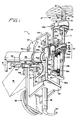
- the rolling and reforming tool 1 of the invention generally comprises a roller cage 3 rotatably mounted within a thrust collar 17, and a tapered mandrel 11 which may be extended into the cage 3 to drive the cage rollers 7a-7d.
- the thrust collar 17 is in turn slidably and resiliently mounted upon a table assembly 20 by means of a pair of spring-loaded guide rods 22a, 22b which are received within a pair of ball-bushings 24a, 24b as shown.
- the table assembly 20 includes a table plate 26 onto which the aforementioned ball-bushings 24a, 24b are mounted, along with a drive train 35 for linking the rotatable mandrel 11 to a reversible, torque-limited air motor 36.
- the entire table assembly is in turn slidably mounted by means of ball-bushings 54a, 54b and guide rods 56a, 56b onto a frame 60.
- the frame 60 includes a single hydraulic lifting cylinder 82 for reciprocating the table assembly 20 from a retracted position to an extended, tube-engaging position wherein the roller cage 3 is positively biased against the open end of a tube 85 in a tubesheet 87.
- the leading edge of the tool 1 is generally complementary in shape to the arcuate profile 90 of the bowl-shaped wall of the primary side of a nuclear steam generator, in order that the tool 1 may be used to reform and roll heat exchange tubes 85 located around the periphery of the tubesheet 87.
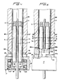
- Figures 5 and 6 best illustrate how the tool 1 operates to reform a tube 85 which is dented in areas 86a, 86b.
- a ring 115 having a pair of opposing dovetails 117a, 117b is laterally slid into complementary dovetail slots 112a, 112b located on a ring support flange 110 which is integrally formed on the top portion of the thrust collar 17.
- the inner diameter D1 of the ring 115 is selected so that it is substantially the same as the minimum inner diameter D2 of the dented tube end.
- a cage 3 having a diameter which is a little less than the inner diameter D2 of the tube end is selected and mounted within the thrust collar 17.
- Figure 6 illustrates why the rollers 7a-7d would "stall” and fail to effect a reformation in the tube end if no ring 115 were present atop the thrust collar 17. Specifically, while it is clear that the mandrel 11 could extend and rotate the rollers 7a-7d, it is also clear that these rollers could in no way cause the cage 3 to rotate within the dented end of the tube 85, since there is no surface upon which they could gain the required traction to rotate the cage 3 around the dented end of the tube 85. Hence, Figure 6 illustrates how the off-round shape of the end of the tube 85 will effectively prevent the rollers 7a-7d from reacting against the inner surface of the tube, rotating the cage, and reforming the end of the tube.
- a ring 115 having an inner diameter Dl which is approximately the same as the minimum inner diameter D2 of the dented end of the tube allows the tool 1 to reform the off-round tube end by providing a reactive surface upon which the rollers 7a-7d may react.
- the rolling and reforming tool 1 of the invention includes a roller cage 3 having four pitched slots 5a-5d, each of which loosely receives a tapered roller 7a-7d, respectively.
- Each of these rollers 7a-7d is both rotatable within, and radially extendable through, its respective pitched slot 5a-5d.
- the pitch of each of the slots 5a-5d is chosen to be a relatively small angle with respect to the axis of rotation of the cage 3. The existence of some pitch or incline in each of the slots 5a-5d is important, because without such a pitch the rollers would not screw into or feed the tapered mandrel 11 into the open end of a tube during the reforming or rolling operation.
- the roller cage 3 also has a centrally disposed bore 9 for receiving the tapered mandrel 11.
- the tapered mandrel 11 drives each of the tapered rollers 7a-7d by both rotating these rollers within their respective slots 5a-5d in the cage 3, as well as by radially extending these rollers toward the inner wall of the tube being reformed or expanded.
- the distal end 13 of the roller cage 3 is tapered in order to facilitate the insertion of the cage 3 within an off-round tube end, while the proximal end 15 of the cage 3 is rotatably mounted within a thrust collar 17 by means of a bearing assembly which will be described in detail later.
- the leading edge of the thrust collar 17 is the narrowest of its edges, in order to facilitate the manipulation of the roller cage 3 into an area of limited access on the tubesheet 87, such as its periphery.
- the thrust collar 17 likewise includes a centrally disposed bore 19 for receiving the tapered mandrel 11.
- both the cage 3 and the thrust bearing 17 are slidably and resiliently mounted onto a table assembly 20 by means of a pair of spring-loaded guide rods 22a, 22b. These guide rods are received within a pair-of ball-bushings 24a, 24b mounted on opposite sides of the table plate 26 of the table assembly 20. While not shown in any of the several Figures, each of the ball-bushings 24a, 24b (as well as ball-bushings 54a, 54b, which will be discussed later) includes a pair of ball bearing assemblies mounted on either end thereof so that each of the guide rods 22a, 22b are circumscribed by ball bearings at the upper and lower portions of the ball-bushings.
- each of the guide rods 22a, 22b are detachably mounted onto a pair of opposing mounting legs 27a, 27b by means of removable cotter pins 28a, 28b, respectively.
- the guide rods 22a, 22b are received within bores present in each of the mounting legs 27a, 27b.
- each of the guide rods 22a, 22b is mounted within a rod-receiving bore in a carriage bar 30.
- the carriage bar 30 is in turn resiliently mounted to the underside of the table assembly 20 by means of a pair of springs 32a, 32b.
- These springs 32a, 32b are connected at their distal ends to a pair of spring brackets 34a, 34b extending from the underside of the table assembly 20, and at their proximal ends to the aforementioned carriage bar 30.
- the springs 32a, 32b bias the mandrel away from the thrust collar, 17 and its roller cage 3, so that the upper and relatively narrow part of the tapered mandrel 11 extends through the centrally disposed bore 19 within the thrust collar 17 when the tool is not in use.
- the cage 3 is inserted into the end of a tube, and the biasing force applied by the springs 32a, 32b is overcome so that the table assembly 20 and the thrust collar 17 are pressed relatively closer together.
- the thicker, lower section of the tapered mandrel 11 is then introduced through the thrust collar 17 and the centrally disposed bore in the roller cage 3 in order that the mandrel 11 might drive the rollers 7a-7d of the roller cage 3.
- the springs 32a, 32b help withdraw the mandrel 11 out of the cage 3 and the thrust collar 17, as will be described in more detail hereinafter.
- a drive train 35 is mounted on the underside of the table plate 26 of the table assembly 20. On its trailing side, the drive train 35 is connected to a reversible, torque-limited air motor which drives the tapered mandrel 11, and ultimately the rollers 7a-7d in the roller cage 3, to reform or to expand a tube end.
- this air motor 36 is preferably a 500 rpm Model F30LR8TA-5 pneumatic motor manufactured by the Stanley Air Tools Division of Stanley. Works, Inc., of Cleveland, Ohio.
- the pivotal drive joint 37 which is a part of the aforementioned commercially available air motor is preferably adjusted to a 45° angle, as indicated in Figure 3.
- the drive train 35 is detachably connected to the tapered mandrel 11 by means of a cotter pin assembly 38, having a cotter pin 39 which is insertable through a bore (not shown) in an insert 40.
- a cotter pin assembly 38 is important in the operation of the invention, since it makes it very easy to exchange one mandrel 11 for another.
- the reversible, torque-limited air motor 36 includes a compressed air line 41 for powering the motor, and an air flow diverter button 42 for reversing the direction of the motor (and hence the rotational direction of the tapered mandrel 11).
- This air flow diverter button 42 is controlled by means of a wedge-receiving block 43 connected thereto, which interacts with a wedge 44 connected to the output shaft of a reversible hydraulic cylinder 45.
- the air flow diverter button 42 is normally biased outwardly in the position shown in Figure 1 when the wedge 44 is in a retracted position.
- the final noteworthy features of the table assembly 20 include the tapered shape of the leading edge 50 of the table plate 26, and the ball-bushings 54a, 54b which are mounted onto opposite sides near the relatively flat trailing edge 52 of this plate. As was the case with the tapered edge of the thrust collar 17, the provision of a tapered edge 50 on the table plate 26 renders the tool 1 as a whole more easily manipulable in areas of difficult access within the primary side of a nuclear steam generator.
- the frame 60 generally comprises a vertically oriented strongback plate 62 which is integrally connected to an upper support plate 64 and a lower support plate 66.
- Strongback plate 62 includes at its bottom end a coupling plate 68 for mechanically connecting the tool 1 to a robotic arm, such as the ROSA arm disclosed and claimed in U.S. Patent No. 4,262,402, assigned to Westinghouse Electric Corporation, the assignee of the present invention.
- a light shield 70 Located immediately above the coupling plate 68 on the strongback plate 62 is a light shield 70 for protecting and for columnating the light generated by a light bulb 71.
- the strongback plate 62 includes a pair of brackets 74a, 74b for mounting a television camera 76 having a lens (not shown) disposed over the light 71, and aimed toward the roller cage 3.
- the provision of a light 71 and a television camera 76 renders the tool 1 remotely controllable by means of a robotic arm such as the above-mentioned ROSA arm.
- a cloverleaf cutout 78 is present in the upper plate 64 of the frame 60.
- the lower plate 66 includes a bracket 80 for mounting a hydraulic lifting cylinder 82 thereon.
- the distal end of the operating rod is connected to a tongue extending out of the flat trailing edge 52 of the table plate 26.
- An air hose 84 is coupled to the bottom portion of the hydraulic cylinder 82 in order to selectively extend or retract the operating rod 83. Because the operating rod 83 links the frame 60 to the table assembly 20 which is in turn slidably movable over guide rods 56a, 56b, the actuation or deactuation of the hydraulic cylinder 82 will either lift the thrust collar 17 and its roller cage 3 into a tube-engaging position, or retract it back down into a non-tube-engaging position, as is indicated in phantom in Figure 2.
- the profile of the entire leading edge of the reforming and rolling tool 1 is complementary in shape to the arcuate wall 90 of the bowl-shaped primary side of a nuclear steam generator.
- Such configuring of the various principal components of the reforming and rolling rool 1 again enhances the manipulability of the tool 1 as a whole in tight spaces within the primary side of a nuclear steam generator.
- the thrust collar 17 includes a casing 95 for holding a bearing assembly 97.
- the bearing assembly 97 in turn contains a plurality of roller bearings 98 disposed over the top and bottom sides of the proximal annular flange 99 of the roller cage 3.
- Both the structure of the bearing assembly 97 and its interaction with the proximal flange 99 of the roller cage 3 is conventional, and accordingly no specific description of the same will be given herein. Suffice to say that the rollers 98 of the bearing assembly 97 allow the cage 3 to rotate within the thrust collar 17 with a minimum amount of friction despite the application of a tensile load between the cage 3 and the thrust collar 17 when the cage 3 is screwing or feeding itself up through the open end of a tube 85.
- the retainer plate 103 includes the previously mentioned bore 19 for receiving the tapered mandrel 11. Bore 19 is concentrically disposed with respect to another centrally disposed bore 101 which extends throughout the longitudinal axis of the roller cage 3.
- a ring support flange 110 Located on top of the thrust collar 17 is a ring support flange 110. This flange 110 includes a pair of opposing dovetail slots 112a, 112b for receiving complementary dovetails 117a, 117b present on the bottom side of a ring 115.
- FIG. 1 The operation of the reforming and rolling tool 1 may best be understood with reference to Figures 2, 4, 5 and 6.
- Figures 2 and 4 illustrate the operation of the tool 1 in expanding the open end of a heat exchange tube 85 within a bore in a tubesheet 87 in order to eliminate the sludge-collecting annular space 88 between the outer wall of the tube 85 and the inner wall of the bore of the tubesheet 87 which surrounds it.
- the previously mentioned robotic arm positions the frame 60 of the tool 1 so that the tapered edge 13 of the roller cage 3 is aligned with the open end of the tube 85.
- the operating rod of the hydraulic cylinder 82 is in a retracted, non-actuated position.
- the hydraulic lifting cylinder 82 is actuated. The operating rod overcomes the force of the springs 32a, 32b and pushes the roller cage 3 into the open end of the tube 85 until the cage 3 is completely inserted therein.
- the lower, thicker part of the mandrel 11 is pushed through the bore 19 of the thrust collar 17 and thence through the roller cage 3, thereby engaging the mandrel 11 against the rollers 7a-7d, which in turn radially extends them against the inner wall of the tube 85.
- the reversible pneumatic motor 86 is then actuated in order to rotate the rollers 7a-7d in a counterclockwise direction (looking down on the tool 1).
- the rollers 7a-7d in turn engage the inner walls of the tube 85, and rotate the entire cage in a counterclockwise direction.
- Figure 4 indicates the result of this operation.
- the mouth of the tube 85 is smoothly expanded outwardly into contact with the inner walls of the surrounding bore of the tubesheet 87.
- the reversible hydraulic cylinder 45 is actuated to drive the wedge 44 into the wedge-receiving block 43, in order to depress the air flow diverter button 42.
- This reverses the direction of the air motor 36, which in turn reverses the direction of rotation of the tapered mandrel 11.
- the hydraulic lifting cylinder 82 is deactuated so that the tensile force applied to the mandrel 11 by the springs 32a, 32b is no longer overcome.
- the mandrel 11 is then withdrawn out of the cage as a result of the spring-assisted unscrewing motion which the rollers 7a-7d apply onto the mandrel 11.
- Figures 5 and 6 illustrate the operation of the tool 1 as a reforming device.
- a rolling cage 3 is selected which has a diameter slightly smaller than the minimum diameter D2 across the dented tube end. If such a cage 3 were inserted into the dented tube end in the manner described with respect to the tube rolling operation, the rollers 7a-7d would align themselves in the "stalled" position illustrated in Figure 6. Even if the tapered mandrel 11 were inserted to its maximum extent through the cage 3 so that the rollers 7a-7d were extended to their maximum radial extent, the rollers 7a-7d still would not engage the inner wall of the tube 85.
- the cage 3 could not rotate when the mandrel 11 was rotated and no reformation of the dented tube end would occur.
- a ring 115 (as illustrated in Figure 5) is mounted over the ring support flange 110 of the thrust collar 17 in the manner previously described, the situation can change radically, so long as the inner diameter Dl of the ring 115 is approximately the same as the minimum diameter D2 across the dented tube end.
- the rollers 7a-7d now have a surface in the form of the inner diameter of the ring 115 to which they can react and against which they can rotate. More precisely, the inner diameter 115 affords a surface against which the rollers 7a-7d can acquire traction.
- This roller traction in turn causes the cage 3 to rotate, and the extended rollers 7a-7d to push the dented regions 86a, 86b radially toward their initial positions, thereby at least partially reforming the dented tube end back into its initial, circular shape.
- cages 3 and rings 115 having successively larger diameters D2 and Dl may have to be used in order to completely reform the dented tube end back into its initial circular shape.
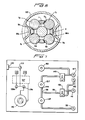
- FIG. 7 illustrates the electrical and pneumatic control circuitry of the rolling and reforming tool 1.
- the electrical circuitry of the control system generally includes a source 120 of 110-volt A.C. current which is connected in parallel to a solenoid connector 124a via a switch 129a, and a powerstat or light dimmer 130 via switch 129b.
- the output of the powerstat is connected to a transformer 127 for stepping the 110-volt potential from source 120 down to a maximum of 12 volts.
- the output of the transformer is in turn connected to light connector 124b.
- switch 129a may be used to actuate or deactuate a solenoid-operated valve (not shown) which controls the flow of air to motor 36, while switch 129b and powerstat 130 may be used to actuate the light 71 for the television camera 76 and to regulate the brightness of this light, respectively.
- compressed air is admitted through inlet 132 via the solenoid-operated valve, where it passes through air filter 134.
- the compressed air then flows to T-junction 135 and branches off into conduits 136 and 144 as shown.
- Air flowing through conduit 136 flows through a three-way valve 139 which is the valve within the reversible air motor 136 operatively engaged to the air flow diverter button 42. Air leaving thr-ae-way valve 139 can flow through either outlet 141 or 143.
- the air motor 136 will rotate the mandrel 11 in a counterclockwise, cage-tightening direction (looking down on the tool 1); however, if the three-way valve 139 diverts the compressed air to outlet 143, the mandrel 11 will be rotated in a counterclockwise, cage-loosening direction.
- valve 145 controls the flow of compressed air to an outlet 147 which leads to the hydraulic lifting cylinder 82 through the air line 84.
- an air gauge 150 is pneumatically connected between the valve 145 and outlet 147.
Landscapes
- Engineering & Computer Science (AREA)
- Mechanical Engineering (AREA)
- Earth Drilling (AREA)
- Heat Treatment Of Articles (AREA)
- Pens And Brushes (AREA)
Applications Claiming Priority (2)
| Application Number | Priority Date | Filing Date | Title |
|---|---|---|---|
| US748877 | 1985-06-26 | ||
| US06/748,877 US4615198A (en) | 1985-06-26 | 1985-06-26 | Apparatus and method for reforming and rolling tube ends |
Publications (3)
| Publication Number | Publication Date |
|---|---|
| EP0206835A2 true EP0206835A2 (fr) | 1986-12-30 |
| EP0206835A3 EP0206835A3 (en) | 1987-01-28 |
| EP0206835B1 EP0206835B1 (fr) | 1990-02-21 |
Family
ID=25011317
Family Applications (1)
| Application Number | Title | Priority Date | Filing Date |
|---|---|---|---|
| EP86304973A Expired EP0206835B1 (fr) | 1985-06-26 | 1986-06-26 | Dispositif et procédé pour former et rouler des tronçons déformés de tuyaux |
Country Status (4)
| Country | Link |
|---|---|
| US (1) | US4615198A (fr) |
| EP (1) | EP0206835B1 (fr) |
| JP (1) | JPS61296922A (fr) |
| ES (1) | ES8801424A1 (fr) |
Families Citing this family (10)
| Publication number | Priority date | Publication date | Assignee | Title |
|---|---|---|---|---|
| US4713952A (en) * | 1986-02-05 | 1987-12-22 | Westinghouse Electric Corp. | Tool and method for rotopeening the peripheral tubes in a tubesheet |
| US5454152A (en) * | 1993-09-16 | 1995-10-03 | Sierracin Corporation | Roller swaging tool |
| US6527732B1 (en) | 2000-10-17 | 2003-03-04 | Micro Therapeutics, Inc. | Torsionally compensated guidewire |
| US8216628B2 (en) * | 2001-09-06 | 2012-07-10 | Corn Products Development, Inc. | Process for purifying starches |
| JP4851815B2 (ja) * | 2006-03-01 | 2012-01-11 | 株式会社スギノマシン | 拡管装置 |
| CN101670403B (zh) | 2008-09-12 | 2011-01-26 | 中山市奥美森工业有限公司 | 一种组合式胀管机 |
| US8777277B2 (en) | 2010-12-02 | 2014-07-15 | Victaulic Company | Pipe element having shoulder, groove and bead and methods and apparatus for manufacture thereof |
| SG2014009591A (en) | 2011-09-02 | 2014-09-26 | Victaulic Co Of America | Spin forming method |
| CN102896544B (zh) * | 2011-12-30 | 2014-10-22 | 中山市奥美森工业有限公司 | 一种冰箱储液器自动加工设备的管件升降装置 |
| CN108941342B (zh) * | 2018-08-28 | 2024-08-09 | 航珍航空技术(上海)有限公司 | 一种内旋挤压成型机 |
Citations (1)
| Publication number | Priority date | Publication date | Assignee | Title |
|---|---|---|---|---|
| US4262402A (en) | 1978-10-18 | 1981-04-21 | Westinghouse Electric Corp. | Method for servicing a steam generator |
Family Cites Families (16)
| Publication number | Priority date | Publication date | Assignee | Title |
|---|---|---|---|---|
| US842877A (en) * | 1906-03-23 | 1907-02-05 | Charles Frankel | Garment-form. |
| US898202A (en) * | 1907-01-18 | 1908-09-08 | John W Faessler | Boiler-tube expander. |
| US1516704A (en) * | 1922-01-11 | 1924-11-25 | Carl F Braun | Tube-expanding tool |
| US2448512A (en) * | 1947-01-08 | 1948-09-07 | Brackett Newell | Tube expander |
| US3247695A (en) * | 1962-08-17 | 1966-04-26 | Carrier Corp | Tube expansion tool |
| US3188850A (en) * | 1963-02-21 | 1965-06-15 | Carrier Corp | Tube expander tool |
| US3354680A (en) * | 1964-11-05 | 1967-11-28 | Platmanufaktur Ab | Method of producing a conical pail and machine for carrying out the method |
| US3426565A (en) * | 1966-03-11 | 1969-02-11 | Thomas C Wilson Inc | Tube expander |
| US3528498A (en) * | 1969-04-01 | 1970-09-15 | Wilson Ind Inc | Rotary cam casing swage |
| US3656333A (en) * | 1970-05-21 | 1972-04-18 | Clemens A Kruse Jr | Cylindrical surface finishing tool |
| US4166313A (en) * | 1975-08-01 | 1979-09-04 | The Babcock & Wilcox Company | Nuclear fuel element nut retainer cup tool |
| JPS5462964A (en) * | 1977-10-28 | 1979-05-21 | Sugino Mach | Pipe enlarging apparatus |
| US4178787A (en) * | 1978-08-10 | 1979-12-18 | Westinghouse Electric Corp. | Remotely operated tube expanding tool and support |
| US4242893A (en) * | 1979-05-22 | 1981-01-06 | Dresser Industries, Inc. | Stop collar for tube expander |
| FR2486834A1 (fr) * | 1980-07-18 | 1982-01-22 | Unicum Sa | Tete d'expansion pour un appareil destine a evaser ou a elargir les extremites des tubes ou similaires |
| US4580426A (en) * | 1984-02-27 | 1986-04-08 | Westinghouse Electric Corp. | Hybrid expansion apparatus and process |
-
1985
- 1985-06-26 US US06/748,877 patent/US4615198A/en not_active Expired - Lifetime
-
1986
- 1986-06-23 ES ES556469A patent/ES8801424A1/es not_active Expired
- 1986-06-26 EP EP86304973A patent/EP0206835B1/fr not_active Expired
- 1986-06-26 JP JP61148347A patent/JPS61296922A/ja active Pending
Patent Citations (1)
| Publication number | Priority date | Publication date | Assignee | Title |
|---|---|---|---|---|
| US4262402A (en) | 1978-10-18 | 1981-04-21 | Westinghouse Electric Corp. | Method for servicing a steam generator |
Also Published As
| Publication number | Publication date |
|---|---|
| EP0206835B1 (fr) | 1990-02-21 |
| JPS61296922A (ja) | 1986-12-27 |
| US4615198A (en) | 1986-10-07 |
| EP0206835A3 (en) | 1987-01-28 |
| ES8801424A1 (es) | 1988-01-01 |
| ES556469A0 (es) | 1988-01-01 |
Similar Documents
| Publication | Publication Date | Title |
|---|---|---|
| EP0008386B1 (fr) | Positionneur de sonde | |
| EP0206835B1 (fr) | Dispositif et procédé pour former et rouler des tronçons déformés de tuyaux | |
| US7314343B2 (en) | Miniature manipulator for servicing the interior of nuclear steam generator tubes | |
| US4561816A (en) | Remote manipulator arm for nuclear generator repair | |
| US4918808A (en) | Device for remotely lining a steam generator tube of a pressurized water nuclear reactor | |
| JPS62263833A (ja) | 蒸気発生器の周辺管をライニング加工する方法及び装置 | |
| US4672741A (en) | End effector apparatus for positioning a steam generator heat exchanger tube plugging tool | |
| EP0300458B1 (fr) | Méthode de soudage à rayon laser pour une surface de périmètre à l'intérieur d'un tuyau | |
| JPH07256365A (ja) | 管状部材の半径方向拡張装置及び方法 | |
| US4829648A (en) | Apparatus and method for simultaneously loading a reinforcing sleeve and mandrel into a tube | |
| JPH0712983A (ja) | 管プラグ検査装置 | |
| JP5172144B2 (ja) | 熱交換器の水室に対して作業を行う装置及び方法 | |
| EP0238303B1 (fr) | Méthode et dispositif pour couper des tubes | |
| US5265667A (en) | Robotic arm for servicing nuclear steam generators | |
| US5164151A (en) | Manipulator system for an enclosure with a limited access point | |
| CA2262335C (fr) | Assemblage de lance segmente | |
| US5165470A (en) | Plugging apparatus for heat exchanger | |
| US4876871A (en) | Flexible hardroll mandrel assembly for sleeving peripherally located heat exchanger tubes | |
| EP0652069B1 (fr) | Appareil et procédé pour positionner sélectivement des modules d'outil pour une opération de soudage d'un tube | |
| US4713952A (en) | Tool and method for rotopeening the peripheral tubes in a tubesheet | |
| JP2686270B2 (ja) | 伝熱管補修スリーブの除去装置 | |
| EP0001893B1 (fr) | Dispositif pour le découpage de tubes de l'intérieur | |
| CA1289738C (fr) | Dispositif de telealimentation en pieces cylindriques d'une machine automatique, comme une machine realisant la pose des tubes du generateur de vapeur d'un reacteur nucleaire a eau pressurisee | |
| JPS60108604A (ja) | ボイラ−内で使用するための遠隔マニピユレ−タ | |
| KR20220118177A (ko) | F-타입 증기발생기용 중앙통로부 자동검사장치 |
Legal Events
| Date | Code | Title | Description |
|---|---|---|---|
| PUAI | Public reference made under article 153(3) epc to a published international application that has entered the european phase |
Free format text: ORIGINAL CODE: 0009012 |
|
| PUAL | Search report despatched |
Free format text: ORIGINAL CODE: 0009013 |
|
| AK | Designated contracting states |
Kind code of ref document: A2 Designated state(s): BE CH FR GB IT LI SE |
|
| AK | Designated contracting states |
Kind code of ref document: A3 Designated state(s): BE CH FR GB IT LI SE |
|
| RHK1 | Main classification (correction) |
Ipc: G21C 19/26 |
|
| 17P | Request for examination filed |
Effective date: 19870724 |
|
| 17Q | First examination report despatched |
Effective date: 19880831 |
|
| GRAA | (expected) grant |
Free format text: ORIGINAL CODE: 0009210 |
|
| AK | Designated contracting states |
Kind code of ref document: B1 Designated state(s): BE CH FR GB IT LI SE |
|
| ET | Fr: translation filed | ||
| ITF | It: translation for a ep patent filed | ||
| PLBE | No opposition filed within time limit |
Free format text: ORIGINAL CODE: 0009261 |
|
| STAA | Information on the status of an ep patent application or granted ep patent |
Free format text: STATUS: NO OPPOSITION FILED WITHIN TIME LIMIT |
|
| 26N | No opposition filed | ||
| PGFP | Annual fee paid to national office [announced via postgrant information from national office to epo] |
Ref country code: FR Payment date: 19910325 Year of fee payment: 6 |
|
| PGFP | Annual fee paid to national office [announced via postgrant information from national office to epo] |
Ref country code: SE Payment date: 19910402 Year of fee payment: 6 Ref country code: GB Payment date: 19910402 Year of fee payment: 6 |
|
| PGFP | Annual fee paid to national office [announced via postgrant information from national office to epo] |
Ref country code: BE Payment date: 19910415 Year of fee payment: 6 |
|
| ITTA | It: last paid annual fee | ||
| PGFP | Annual fee paid to national office [announced via postgrant information from national office to epo] |
Ref country code: CH Payment date: 19910702 Year of fee payment: 6 |
|
| PG25 | Lapsed in a contracting state [announced via postgrant information from national office to epo] |
Ref country code: GB Effective date: 19920626 |
|
| PG25 | Lapsed in a contracting state [announced via postgrant information from national office to epo] |
Ref country code: SE Effective date: 19920627 |
|
| PG25 | Lapsed in a contracting state [announced via postgrant information from national office to epo] |
Ref country code: LI Effective date: 19920630 Ref country code: CH Effective date: 19920630 Ref country code: BE Effective date: 19920630 |
|
| BERE | Be: lapsed |
Owner name: WESTINGHOUSE ELECTRIC CORP. Effective date: 19920630 |
|
| GBPC | Gb: european patent ceased through non-payment of renewal fee |
Effective date: 19920626 |
|
| PG25 | Lapsed in a contracting state [announced via postgrant information from national office to epo] |
Ref country code: FR Effective date: 19930226 |
|
| REG | Reference to a national code |
Ref country code: CH Ref legal event code: PL |
|
| REG | Reference to a national code |
Ref country code: FR Ref legal event code: ST |
|
| EUG | Se: european patent has lapsed |
Ref document number: 86304973.0 Effective date: 19930109 |
|
| PG25 | Lapsed in a contracting state [announced via postgrant information from national office to epo] |
Ref country code: IT Free format text: LAPSE BECAUSE OF NON-PAYMENT OF DUE FEES;WARNING: LAPSES OF ITALIAN PATENTS WITH EFFECTIVE DATE BEFORE 2007 MAY HAVE OCCURRED AT ANY TIME BEFORE 2007. THE CORRECT EFFECTIVE DATE MAY BE DIFFERENT FROM THE ONE RECORDED. Effective date: 20050626 |