EP0206896A1 - Modulare Stopfbüchse für die Durchführung einer zylindrischen Leitung durch eine Wand - Google Patents
Modulare Stopfbüchse für die Durchführung einer zylindrischen Leitung durch eine Wand Download PDFInfo
- Publication number
- EP0206896A1 EP0206896A1 EP86401222A EP86401222A EP0206896A1 EP 0206896 A1 EP0206896 A1 EP 0206896A1 EP 86401222 A EP86401222 A EP 86401222A EP 86401222 A EP86401222 A EP 86401222A EP 0206896 A1 EP0206896 A1 EP 0206896A1
- Authority
- EP
- European Patent Office
- Prior art keywords
- cable gland
- wall
- ring
- annular
- thread
- Prior art date
- Legal status (The legal status is an assumption and is not a legal conclusion. Google has not performed a legal analysis and makes no representation as to the accuracy of the status listed.)
- Withdrawn
Links
- 230000000295 complement effect Effects 0.000 claims abstract description 13
- 230000006835 compression Effects 0.000 claims abstract description 11
- 238000007906 compression Methods 0.000 claims abstract description 11
- 210000004907 gland Anatomy 0.000 claims description 59
- 239000012528 membrane Substances 0.000 claims description 8
- 238000004873 anchoring Methods 0.000 claims description 7
- 239000004033 plastic Substances 0.000 claims description 6
- 229920003023 plastic Polymers 0.000 claims description 6
- 230000000903 blocking effect Effects 0.000 claims description 5
- 238000002788 crimping Methods 0.000 claims description 5
- 238000012423 maintenance Methods 0.000 claims description 3
- 238000003892 spreading Methods 0.000 claims description 3
- 230000002093 peripheral effect Effects 0.000 claims description 2
- 238000003466 welding Methods 0.000 claims description 2
- 238000007789 sealing Methods 0.000 description 6
- 238000005192 partition Methods 0.000 description 5
- 229920001971 elastomer Polymers 0.000 description 3
- 238000003780 insertion Methods 0.000 description 3
- 230000037431 insertion Effects 0.000 description 3
- 238000012856 packing Methods 0.000 description 3
- 229920002635 polyurethane Polymers 0.000 description 3
- 239000004814 polyurethane Substances 0.000 description 3
- 241000722921 Tulipa gesneriana Species 0.000 description 2
- 239000003638 chemical reducing agent Substances 0.000 description 2
- 239000000428 dust Substances 0.000 description 2
- 239000000806 elastomer Substances 0.000 description 2
- 239000000463 material Substances 0.000 description 2
- 238000010079 rubber tapping Methods 0.000 description 2
- 229910001369 Brass Inorganic materials 0.000 description 1
- 208000031968 Cadaver Diseases 0.000 description 1
- OKTJSMMVPCPJKN-UHFFFAOYSA-N Carbon Chemical compound [C] OKTJSMMVPCPJKN-UHFFFAOYSA-N 0.000 description 1
- 244000043261 Hevea brasiliensis Species 0.000 description 1
- 229920002292 Nylon 6 Polymers 0.000 description 1
- 238000005452 bending Methods 0.000 description 1
- 239000010951 brass Substances 0.000 description 1
- 210000004027 cell Anatomy 0.000 description 1
- 230000006866 deterioration Effects 0.000 description 1
- 230000000694 effects Effects 0.000 description 1
- 239000013536 elastomeric material Substances 0.000 description 1
- 229910002804 graphite Inorganic materials 0.000 description 1
- 239000010439 graphite Substances 0.000 description 1
- 230000014759 maintenance of location Effects 0.000 description 1
- 238000004519 manufacturing process Methods 0.000 description 1
- 238000000465 moulding Methods 0.000 description 1
- 229920003052 natural elastomer Polymers 0.000 description 1
- 229920001194 natural rubber Polymers 0.000 description 1
- 238000009428 plumbing Methods 0.000 description 1
- 229920001084 poly(chloroprene) Polymers 0.000 description 1
- 238000003825 pressing Methods 0.000 description 1
- 230000001681 protective effect Effects 0.000 description 1
- 238000011144 upstream manufacturing Methods 0.000 description 1
Images



Classifications
-
- H—ELECTRICITY
- H02—GENERATION; CONVERSION OR DISTRIBUTION OF ELECTRIC POWER
- H02G—INSTALLATION OF ELECTRIC CABLES OR LINES, OR OF COMBINED OPTICAL AND ELECTRIC CABLES OR LINES
- H02G3/00—Installations of electric cables or lines or protective tubing therefor in or on buildings, equivalent structures or vehicles
- H02G3/02—Details
- H02G3/06—Joints for connecting lengths of protective tubing or channels, to each other or to casings, e.g. to distribution boxes; Ensuring electrical continuity in the joint
- H02G3/0616—Joints for connecting tubing to casing
- H02G3/0625—Joints for connecting tubing to casing with means for preventing disengagement of conductors
-
- F—MECHANICAL ENGINEERING; LIGHTING; HEATING; WEAPONS; BLASTING
- F16—ENGINEERING ELEMENTS AND UNITS; GENERAL MEASURES FOR PRODUCING AND MAINTAINING EFFECTIVE FUNCTIONING OF MACHINES OR INSTALLATIONS; THERMAL INSULATION IN GENERAL
- F16L—PIPES; JOINTS OR FITTINGS FOR PIPES; SUPPORTS FOR PIPES, CABLES OR PROTECTIVE TUBING; MEANS FOR THERMAL INSULATION IN GENERAL
- F16L5/00—Devices for use where pipes, cables or protective tubing pass through walls or partitions
- F16L5/02—Sealing
- F16L5/06—Sealing by means of a swivel nut compressing a ring or sleeve
-
- H—ELECTRICITY
- H02—GENERATION; CONVERSION OR DISTRIBUTION OF ELECTRIC POWER
- H02G—INSTALLATION OF ELECTRIC CABLES OR LINES, OR OF COMBINED OPTICAL AND ELECTRIC CABLES OR LINES
- H02G3/00—Installations of electric cables or lines or protective tubing therefor in or on buildings, equivalent structures or vehicles
- H02G3/02—Details
- H02G3/06—Joints for connecting lengths of protective tubing or channels, to each other or to casings, e.g. to distribution boxes; Ensuring electrical continuity in the joint
- H02G3/0616—Joints for connecting tubing to casing
Definitions
- the present invention relates to cable glands for maintaining an electrical pipe, a tube, a cable or a rod passing through a wall while ensuring sealing on either side of the wall.
- the packing is compressed using a nut or an annular screw.
- the cable gland is most often fixed using a nut which is fitted to the threaded end of the body of the cable gland, on the other side of the wall traversed, which requires access to the other side of the wall.
- the compression of the gasket is generally carried out towards the middle of the body of the cable gland and the deformation capacity of the gasket is limited and allows tightening only of pipes of diameters which are not very different for a given cable gland, with often an excessive torsional force on the sheath surrounding the cable, or other pipe, which can lead to the deterioration of this sheath during blocking.
- the invention aims to overcome the inconveniences nients of conventional cable glands, and in particular to allow the production of cable glands for various applications from a reduced number of standardized parts.
- the subject of the invention is a modular cable gland for maintaining and sealing around an electrical pipe, tube, cable, rod, or the like passing through a wall, which comprises a tubular body containing a compressible lining pressed by an annular compression member, characterized in that the body has means for securing to a plurality of interchangeable complementary members for holding the cable gland on the wall, and / or maintaining the pipeline.
- the body can thus have at its end passing through the wall, an annular abutment shoulder limiting a thread which can cooperate at will, for fixing the stuffing box on the wall with a thread of the wall, a locking nut on the face. of the wall opposite to that on which the shoulder abuts, a reduction or an amplifier of the diameter of the thread, an intermediate socket which can be secured to the wall.
- the annular compression member of the lining can be constituted by an annular nut screwing on the end of the body opposite to the means of securing to the wall to compress a lining against an internal shoulder of the body, characterized in that the nut has, at its end opposite to the body, means for securing by screwing, snapping, crimping, or welding, to interchangeable complementary tightening, anchoring, or guiding members of a pipe through the cable gland.
- At least one of the interchangeable complementary members may include securing means at least one other interchangeable complementary member.
- the nut is extended by a semi-toroidal curved frustoconical narrowing, against which a lining is pressed in abutment on a shoulder of the end of the body, thus subjected to a centripetal creep ensuring its tightening on pipes of a wide range of diameters.
- the lining is advantageously made of elastomer and has, in the absence of compression, an external frustoconical shape opposite the narrowing extending the nut, and a cylindrical internal bore.
- the seal is housed in the compression member constituted by a cap screwing on the body and bears, on the one hand on the end edge of the body and, on the other hand, on a ring secured axially to the cap but free to rotate.
- the ring is extended by an annular thread projecting axially through the cap, for fixing an auxiliary member for radial retention and guiding of the pipe, or a temporary axial protective cap. thread.
- the thread of the body to cooperate with a tapping of a clamping ring which is free axially but locked in rotation inside an elastic multi-branch annular clamp, insertable in a circular orifice. of the wall with little play, and comprising means for pressing on the wall on the side of the cable gland, the screwing of the body in the clamping ring attracting the ring towards the body by spreading the branches of the clamp on the other side of the wall.
- the clamping ring internally threaded, may have an external cylindrical convexity complementary to an internal concavity of the branches of the clamp, with a possible lug projecting radially between two branches of the clamp.
- the cable gland is advantageously associated with a fixing sleeve constituted by an annular threaded ring, limited on one side by an annular flange of abutment on the accessible face of the wall, and extended opposite by an externally bi-conical part swollen in its median part crossing the wall, and cut by several longitudinal slots in a plurality of radial fingers forming a compressible clamp during the insertion of the clamp through the wall, and expandable when screwing the thread of the gland body into the thread of the ring.
- a fixing sleeve constituted by an annular threaded ring, limited on one side by an annular flange of abutment on the accessible face of the wall, and extended opposite by an externally bi-conical part swollen in its median part crossing the wall, and cut by several longitudinal slots in a plurality of radial fingers forming a compressible clamp during the insertion of the clamp through the wall, and expandable when screwing the thread of the gland body into the thread of the ring.
- Such a socket can be molded in one piece from non-rigid plastic, at least one of the lateral faces of the flange having at least one coaxial annular rib for compressible sealing against the wall, or the annular abutment shoulder of the body. of the cable gland, vice versa.
- This ring may include a temporary axial obturation membrane, to which it is connected by a frangible circular zone, which constitutes a frangible cover formed by molding at the end of the thread of the ring, and which comes off at the end of screwing of the body of the body. cable gland in the ring.
- a cable gland according to the invention pre-equipped with such a socket, but partially screwed so as to maintain the socket on the end of the body, but without rupture or detachment of the cover until the establishment by introduction of the sleeve into an orifice in a wall and screwing the body fully into the ring.
- the body and the cap have externally means for gripping by a screwing blocking tool, and the cap has externally, in addition, manual gripping means for rapid screwing preliminary to blocking.
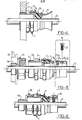
- the cable gland shown in Figures 1 and 2 comprises a tubular body 3 whose end called to pass through the wall has a thread 6, and whose other end has an internal terminal shoulder 25 on which a lining 4 comes to bear .
- This gasket has the shape of a biconical circumference tank, while its internal bore is cylindrical.
- the lining 4 is compressed against the shoulder 25 by a nut 5 having a frustoconical semi-toric extension 26.
- This arrangement allows the packing 4 to creep in the direction of the pipe 12 with, possibly, an overflow on the outside (FIG. 2) which allows tightening in a large range of diameters.
- the lining can advantageously be made of natural rubber, polyurethane or neoprene, more particularly of hardness 75 Shore A + 5.
- the end of the nut is terminated externally by an external spoiler 7 intended for the possible crimping of complementary members such as a flared tulip end 9 (FIGS. 3, 4) which makes it possible to avoid harmful deformations of the pipe 12, in gradually limiting its overflow at the outlet of the cable glands, or an anchoring module 11 ( Figures 7 and 8) consisting of a ring 28 having at one of its ends a crimping skirt 27, and in its middle part a groove 29 allowing the clamping of a collar 30, 31 with screws 32 of the type commonly used in plumbing to ensure a more positive maintenance of the pipe 12.
- an external spoiler 7 intended for the possible crimping of complementary members such as a flared tulip end 9 (FIGS. 3, 4) which makes it possible to avoid harmful deformations of the pipe 12, in gradually limiting its overflow at the outlet of the cable glands, or an anchoring module 11 ( Figures 7 and 8) consisting of a ring 28 having at one of its ends a crimping skirt
- the ring 28 may have at its end opposite the skirt 27 a spoiler 7 allowing, in turn, the crimping of another complementary member such as a tulip 9 ( Figures 7 and 8).
- the thread 6 is limited by a shoulder 13 and allows various applications.
- the body 3 can be screwed directly into a thread 14 of a wall 2 ( Figures 3 and 4). It can also receive a nut 8 which is screwed on the other side of the wall 2 after introduction of the body 3 into a smooth hole in the wall ( Figures 1 and 2).
- a thread diameter reducer such as 14 (FIGS. 5 and 6) which is constituted by a shouldered ring comprising a thread screwing on the thread 6 of the body 3, and a thread 6a of diameter smaller than the thread 6 of the body. 3.
- the ring 14 may include a thread 6b of a larger diameter terminated by a shoulder 33, as indicated in dotted lines in FIG. 5.
- FIGS. 5 and 6 show a variant 7a, 27a for fixing an anchoring module 10 by snapping on a rib of frustoconical section 27a in a groove with a conical edge 7a of the nut 5.
- the rib 27a is cut into sections by slots 34 ensuring sufficient elasticity for the latching of a socket 35 having one, or preferably, three tappings at 120 ° 36, into which are screwed in needle screws 37 ensuring a positive anchoring of a pipe 12.
- the threaded end 6 of the body 3 can also receive a fixing sleeve 15 through an orifice in a wall accessible from one side only, as shown in FIGS. 9 and 10.
- the sleeve 15 is essentially constituted by a threaded ring 16, one side of which ends in a flange 17 having, on each of its faces, annular coaxial ribs 22, 23 which seal, respectively against the shoulder 13 of the body 3 of the cable gland, and against the wall 2.
- the threaded ring 16 is extended, in its part called to pass through the wall 2, by a clamp 21 formed by a plurality of radial fingers 20 delimited by longitudinal slots 19.
- the outer surface of the clamp 21 is biconical, which allows its easy insertion through the orifice of the wall by radial compression, and its anchoring behind the wall when the thread 6 of the body 3 is screwed in fully, by development of the fingers 20, due to the internal frustoconical surface of the fingers 20.
- the sleeve 15 further comprises a cover frangible 24 at the end of the thread of the ring 16, which detaches therefrom as indicated in FIG. 10 when the body 6 is fully screwed into the socket 15.
- the user can, at will, place such a socket 15 on standby in a wall opening of which it provides sealing until a cable gland 1 is put in place.
- a socket 15 in a wall orifice with a cable gland 1 not fully screwed which allows the seal to fill its sealing role until the moment of fitting a pipe 12 which will cause the body 1 to be screwed to the bottom.
- Such a socket can in particular be molded in polyurethane, and can be used for fixing in sheets of variable thicknesses, for example from 0.5 to 3 mm at least, ensuring, after expansion due to the screwing of the body of the press tow, a very effective anchoring commonly exceeding a pulling force of 500 N for pipes from 7.5 to 12.5 mm in diameter.
- the cable gland shown in the variant of FIGS. 11 to 13 essentially comprises a tubular body 101, a gasket 102, a ring 104 and a cap 103.
- the body 101 has, at its end called to be fixed in the partition to pass through, a thread 123 and at its opposite end a second thread 124 in which the cap 103 is screwed.
- the body 101 has a hexagonal gripping surface 119 for a tightening wrench by screwing, while the cap 103 also has a hex 119 and in addition a 120 knurling which allows rapid screwing by hand before locking with a key.
- the thread 124 of the body 101 has, in the direction of the cap 103, a flat bearing face 125, on which comes the edge of a seal 122 whose exterior, in the direction of the cap 103, has a chamfer 122. On this chamfer 122 comes to carry the internal open face 121 of the ring 104, the corresponding conical external part of which comes to bear against a corresponding conical part 127 of the cap 103.
- the threaded end 123 of the body 101 can be used directly for fixing the cable gland in a tapped hole, or in a smooth hole with conventional locking by a nut on the other face of the wall.
- the thread 123 can also be screwed into the thread 108 of a clamping ring 109 whose convex outer face 114 is biconical and is normally housed in a corresponding surface 115 of teeth 113 coming from a flange 112 making it possible to limit insertion.
- annular pliers 110 in a smooth hole in a partition 111.
- the ring 109 advantageously comprises a frangible part 117 constituting a temporary axial obturation membrane connected to the ring 109 by an annular zone of lesser resistance 118. Lugs 116 projecting from the periphery of the ring 109 are inserted between two teeth 113 of the clamp 110. Thus, the ring 109 is locked in rotation, but can slide axially relative to the clamp 110.
- the thread 123 penetrates the internal thread 108 freely, until the hexagon 119 comes to bear against the flange 112.
- the ring 109 slides axially in the clamp 110 by spreading the teeth 113 until the end of the body 101 comes to bear against the membrane 117 and causes the rupture of the frangible zone 118 with expulsion of the membrane 117.
- the body 101 is firmly fixed in the clamp 110 which is itself very firmly fixed in the wall 111 by the spacing of the teeth 113 under the effect of the sliding of the ring 109.
- the lugs 116 of the ring 109 prevent any untimely rotation of the ring in the body 110 during tightening.
- the membrane 117 ensuring the shelter from dust if not a certain seal.
- the body 101 can be screwed directly into the ring 109, or the membrane 117 can be removed beforehand by pushing it back by hand or with any tool before screwing the body 101.
- the clamp 110 can be removed beforehand from the partition 111 to do this operation in order to prevent the membrane 117 from falling on the other side of the partition 111.
- the clamp 110 can be made of polyurethane or other plastic material flexible enough to obtain a good seal by contact with the wall 111 and the hexagon 119, as well as a deformation of the teeth 113 without risk of breakage.
- the clamping ring 109 can be made of polyamide 6/6 or of plastic which is hard enough to allow screwing without deformation of the threads of the thread.
- the ring 104 in FIGS. 10 to 13 is replaced by a similar ring 104a extended by a thread 105 supporting the cap 103, as shown in FIG. 14.
Landscapes
- Engineering & Computer Science (AREA)
- Architecture (AREA)
- Civil Engineering (AREA)
- Structural Engineering (AREA)
- General Engineering & Computer Science (AREA)
- Mechanical Engineering (AREA)
- Cable Accessories (AREA)
- Laying Of Electric Cables Or Lines Outside (AREA)
- Insulating Bodies (AREA)
Applications Claiming Priority (4)
| Application Number | Priority Date | Filing Date | Title |
|---|---|---|---|
| FR8509132A FR2583496B1 (fr) | 1985-06-17 | 1985-06-17 | Presse-etoupe modulaire et douille pour sa fixation a travers une paroi |
| FR8509132 | 1985-06-17 | ||
| FR8517652 | 1985-11-29 | ||
| FR8517652A FR2590959B1 (fr) | 1985-11-29 | 1985-11-29 | Presse-etoupe adaptable a la traversee d'une cloison par une canalisation cylindrique |
Publications (1)
| Publication Number | Publication Date |
|---|---|
| EP0206896A1 true EP0206896A1 (de) | 1986-12-30 |
Family
ID=26224568
Family Applications (1)
| Application Number | Title | Priority Date | Filing Date |
|---|---|---|---|
| EP86401222A Withdrawn EP0206896A1 (de) | 1985-06-17 | 1986-06-06 | Modulare Stopfbüchse für die Durchführung einer zylindrischen Leitung durch eine Wand |
Country Status (2)
| Country | Link |
|---|---|
| EP (1) | EP0206896A1 (de) |
| ES (1) | ES8800745A1 (de) |
Cited By (7)
| Publication number | Priority date | Publication date | Assignee | Title |
|---|---|---|---|---|
| EP0410855A1 (de) * | 1989-07-28 | 1991-01-30 | CAPRI-CODEC S.A.:Société anonyme dite | Vorrichtung zur Verankerung in einer glatten Oeffnung einer nur von einer Seite zugänglichen Wand und Stopfbuchse mit einer solchen Vorrichtung |
| EP0515200A1 (de) * | 1991-05-23 | 1992-11-25 | Elkay Electrical Manufacturing Co. Ltd. | Kabelverschraubung |
| DE4225263C1 (de) * | 1992-07-31 | 1994-02-17 | Lapp U I Gmbh & Co Kg | Vorrichtung zur Befestigung von Kabeln, Leitungen, Schläuchen und dergleichen |
| EP0967701A3 (de) * | 1998-06-24 | 2000-02-23 | Anton Hummel Verwaltungs GmbH | Anschlussarmatur mit einem durch Schlitze in Halterungen aufgeteilten Befestigungsvorsprung |
| EP1219881A1 (de) * | 2000-12-29 | 2002-07-03 | Legrand | Auf einer Wand blind befestigtes Element |
| CN102868134A (zh) * | 2012-09-28 | 2013-01-09 | 三一重型装备有限公司 | 电缆连接加固装置及工程机械 |
| FR3081963A1 (fr) * | 2018-05-29 | 2019-12-06 | Grdf | Coffret de branchement etanche destine au raccordement d’une installation domestique au reseau de distribution de gaz |
Citations (5)
| Publication number | Priority date | Publication date | Assignee | Title |
|---|---|---|---|---|
| FR1287517A (fr) * | 1961-02-01 | 1962-03-16 | Dispositif serre-câble | |
| GB908838A (en) * | 1959-07-18 | 1962-10-24 | British Engines Ltd | Improvements in or relating to electric cable glands |
| GB1083612A (en) * | 1963-06-11 | 1967-09-20 | Enfield Rolling Mills Ltd | A clamp or gland for electric cables |
| FR2269226A1 (en) * | 1974-04-25 | 1975-11-21 | Schmitt Ludwig | Cable sealed feed-through for junction boxes - has sealing ring compressed between hollow bolt and inner collar |
| FR2415735A1 (fr) * | 1978-01-26 | 1979-08-24 | Kitagawa Ind Co Ltd | Dispositif de blocage d'articles allonges, notamment de cables sur un organe support |
-
1986
- 1986-06-06 EP EP86401222A patent/EP0206896A1/de not_active Withdrawn
- 1986-06-13 ES ES556839A patent/ES8800745A1/es not_active Expired
Patent Citations (5)
| Publication number | Priority date | Publication date | Assignee | Title |
|---|---|---|---|---|
| GB908838A (en) * | 1959-07-18 | 1962-10-24 | British Engines Ltd | Improvements in or relating to electric cable glands |
| FR1287517A (fr) * | 1961-02-01 | 1962-03-16 | Dispositif serre-câble | |
| GB1083612A (en) * | 1963-06-11 | 1967-09-20 | Enfield Rolling Mills Ltd | A clamp or gland for electric cables |
| FR2269226A1 (en) * | 1974-04-25 | 1975-11-21 | Schmitt Ludwig | Cable sealed feed-through for junction boxes - has sealing ring compressed between hollow bolt and inner collar |
| FR2415735A1 (fr) * | 1978-01-26 | 1979-08-24 | Kitagawa Ind Co Ltd | Dispositif de blocage d'articles allonges, notamment de cables sur un organe support |
Cited By (10)
| Publication number | Priority date | Publication date | Assignee | Title |
|---|---|---|---|---|
| EP0410855A1 (de) * | 1989-07-28 | 1991-01-30 | CAPRI-CODEC S.A.:Société anonyme dite | Vorrichtung zur Verankerung in einer glatten Oeffnung einer nur von einer Seite zugänglichen Wand und Stopfbuchse mit einer solchen Vorrichtung |
| FR2650363A1 (fr) * | 1989-07-28 | 1991-02-01 | Capri Codec Sa | Dispositif d'ancrage dans un trou lisse d'une paroi accessible d'un seul cote, et presse-etoupe comportant un tel dispositif |
| EP0515200A1 (de) * | 1991-05-23 | 1992-11-25 | Elkay Electrical Manufacturing Co. Ltd. | Kabelverschraubung |
| DE4225263C1 (de) * | 1992-07-31 | 1994-02-17 | Lapp U I Gmbh & Co Kg | Vorrichtung zur Befestigung von Kabeln, Leitungen, Schläuchen und dergleichen |
| EP0967701A3 (de) * | 1998-06-24 | 2000-02-23 | Anton Hummel Verwaltungs GmbH | Anschlussarmatur mit einem durch Schlitze in Halterungen aufgeteilten Befestigungsvorsprung |
| US6394690B1 (en) | 1998-06-24 | 2002-05-28 | Anton Hummel Verwaltungs Gmbh | Connection fitting with an attachment projection divided by slits into holding tongues |
| EP1219881A1 (de) * | 2000-12-29 | 2002-07-03 | Legrand | Auf einer Wand blind befestigtes Element |
| FR2819037A1 (fr) * | 2000-12-29 | 2002-07-05 | Legrand Sa | Element a fixer en aveugle sur une paroi |
| CN102868134A (zh) * | 2012-09-28 | 2013-01-09 | 三一重型装备有限公司 | 电缆连接加固装置及工程机械 |
| FR3081963A1 (fr) * | 2018-05-29 | 2019-12-06 | Grdf | Coffret de branchement etanche destine au raccordement d’une installation domestique au reseau de distribution de gaz |
Also Published As
| Publication number | Publication date |
|---|---|
| ES8800745A1 (es) | 1987-11-16 |
| ES556839A0 (es) | 1987-11-16 |
Similar Documents
| Publication | Publication Date | Title |
|---|---|---|
| EP0124131B1 (de) | Verlängerungsstück der Seele eines Koaxialkabels und ein mit einem solchen Verlängerungsstück versehener Verbinder | |
| EP1087168A1 (de) | Vorrichtung zum Verbinden von einem Leitungsende mit einem Anschlussteil | |
| FR2498287A1 (fr) | Dispositif pour le maintien de cables, conduites, tuyaux ou objets analogues au niveau de la traversee d'une paroi | |
| FR2483540A1 (fr) | Verin pneumatique ou hydraulique | |
| FR2941029A1 (fr) | Dispositif d'ancrage d'un element dans une ouverture d'une paroi et raccord equipe d'un tel dispositif | |
| CA3035185A1 (fr) | Dispositif d'entree de cable pour cable electrique sous conduit | |
| EP0206896A1 (de) | Modulare Stopfbüchse für die Durchführung einer zylindrischen Leitung durch eine Wand | |
| FR2583497A1 (fr) | Dispositif pour maintenir une canalisation a la traversee d'une paroi | |
| FR2528533A1 (fr) | Raccord traversant a ecrou tournant pour gaine exterieurement spiralee | |
| FR2492499A1 (fr) | Dispositif de raccordement pour tubes | |
| EP0580222A1 (de) | Abzweigverbindung für eine thermoplastische Rohrleitung | |
| JP2009180258A (ja) | 継手及びそれに装着される検査用プラグ | |
| LU86846A1 (fr) | Raccord pour tuyaux | |
| FR2590959A1 (fr) | Presse-etoupe adaptable a la traversee d'une cloison par une canalisation cylindrique | |
| FR2583496A1 (fr) | Presse-etoupe modulaire et douille pour sa fixation a travers une paroi | |
| FR2517132A1 (fr) | Dispositif d'etancheite et de serrage pour cables electriques | |
| FR2578621A1 (fr) | Dispositif de raccordement amovible pour tuyaux | |
| EP0045038A1 (de) | Befestigung des Endes eines elektrischen Kabels mit einem Aussenleiter mit ringförmigen Rippen im Körper eines Verbindungsstücks | |
| EP1605195B1 (de) | Rohrkupplungssystem und dazu gehöriges Montageverfahren | |
| WO2001059500A1 (fr) | Manchon de fixation pour cables optiques | |
| FR2650051A1 (fr) | Embout de raccordement pour tuyau de matiere synthetique et procede de montage | |
| EP0441686A1 (de) | Vorrichtung zum dichten Verbinden von zwei identischen Rohren | |
| FR2543369A2 (fr) | Dispositif d'etancheite pour connecteur electrique | |
| FR2655122A1 (fr) | Joint d'etancheite pour connecteur electrique, et connecteur qui en est equipe. | |
| FR2636118A1 (fr) | Bague anti-grippage pour chapeau de robinet |
Legal Events
| Date | Code | Title | Description |
|---|---|---|---|
| PUAI | Public reference made under article 153(3) epc to a published international application that has entered the european phase |
Free format text: ORIGINAL CODE: 0009012 |
|
| AK | Designated contracting states |
Kind code of ref document: A1 Designated state(s): AT BE CH DE FR GB IT LI LU NL |
|
| 17P | Request for examination filed |
Effective date: 19870401 |
|
| 17Q | First examination report despatched |
Effective date: 19881109 |
|
| STAA | Information on the status of an ep patent application or granted ep patent |
Free format text: STATUS: THE APPLICATION IS DEEMED TO BE WITHDRAWN |
|
| 18D | Application deemed to be withdrawn |
Effective date: 19890808 |
|
| RIN1 | Information on inventor provided before grant (corrected) |
Inventor name: DE VIENNE, ROBERT |