EP0207017A2 - Insbesondere für Fahrzeuge geeignetes Spülklosett - Google Patents
Insbesondere für Fahrzeuge geeignetes Spülklosett Download PDFInfo
- Publication number
- EP0207017A2 EP0207017A2 EP86830176A EP86830176A EP0207017A2 EP 0207017 A2 EP0207017 A2 EP 0207017A2 EP 86830176 A EP86830176 A EP 86830176A EP 86830176 A EP86830176 A EP 86830176A EP 0207017 A2 EP0207017 A2 EP 0207017A2
- Authority
- EP
- European Patent Office
- Prior art keywords
- apted
- base
- water
- support
- closet
- Prior art date
- Legal status (The legal status is an assumption and is not a legal conclusion. Google has not performed a legal analysis and makes no representation as to the accuracy of the status listed.)
- Granted
Links
Images
Classifications
-
- E—FIXED CONSTRUCTIONS
- E03—WATER SUPPLY; SEWERAGE
- E03D—WATER-CLOSETS OR URINALS WITH FLUSHING DEVICES; FLUSHING VALVES THEREFOR
- E03D5/00—Special constructions of flushing devices, e.g. closed flushing system
Definitions
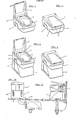
- the water-closet according to the invention is substantially constituted by two basic parts, to which other complementary parts may be added.
- Yhe two basic parts are a seat with a basin for the momentary collection of the sewage, provide with an exhaust opening, and a base, provided with a connection between the basin and the exhaust, receiving at its inside the said basin.
- the complementary parts are a seat-cover , a support for achieving the desired height for the two basic parts, and a recovery reservoir which can be housed within the said support.
- characteristic are the means foreseen to strengthen -the various parts, as well as the distribution of the available room in order to receive the accessory services and to assemble the various parts with each other and together with the vehicle.
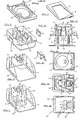
- Fig. 5 shows, according to an isometric view, the seat with the tank
- Fig. 6 shows, according to an isometric view, the inside of the base of the water-closet of the invention
- Fig. 7 shows , according to an isometric view, the seat-cover
- Fig. 8 shows, according to an isometric view, the complementary element acting as a support or container
- Fig. 9 shows according to an isometric view, the recovery tank which can be housed within the support of Fig. 8;
- Figures 10 and 11 show, according to isometric views, two types of small doors which may be applied on the sides of the base of the Figures 1 and 2;
- Fig. 12 shows the water-closet mounted upon its support seen in elevation from behind
- Figures 13, 14 and 15 show in a view from above the seat with the tank, the base and the support, with the corresponding supplementary reservoir, respectively of Figures 5, 6 and 8-9;
- FIGS 16 and 17 show two possible lay-outs for mounting the water-closet of the invention.
- the water-closet of the inventions formed of two basic parts, that is of a seat 1, provided with a collecting basin 3, and a base 2, upon which the seat 1 is applied and which receives inside it the basin 3.
- a supporting element 4 is foreseen which has the main function of bringing the seat 1 and the base 2 to the height which is necessary with respect to the resting plane.
- the seat 1 may be covered by a seat-cover 5 which is suitably ribbed in order to increase its strength and is provided with side traces or prints 6 in order to facilitate its opening.
- the basin 3, preferably integral with the seat 1 is provided with an exhaust hole 6 for the sewage, this hole, through a suitable connecting flange 7, commu nicating with the exhaust true and proper, which starts from the base 2 of the water-closet, as it will be better seen in the following.
- the seat 1 is completed by housings 8 for a tank-cleaning's shower.
- the base 2 (see in particular Figures 6 and 14) which receives on its upper rim the seat 1, has inside itself, on the back side, a support and/or a strenghtening rib 9 and a coupling 10 for a venting or exhalation pipe and, arranged towards the front, a wall or rib 11, having a curved outline, whose purpose is to rib and support the seat 1 and to receive the flexible 12 piping feeding water to the shower 13 which exits from the housing 8 of the seat.
- the flexible piping 12 takes, inside the base 2, the position which is illustrated by dash lines in the Fig. 14, whereas, when the shower 13 is in the extracted position, the flexible piping 12 takes the position which is indicated by full lines. In this way one has the possibility to house the shower in such a way that it will give no trouble during the non-use periods, and in the same time one gets a suitable protection for the water-feeding pipe.
- the base 2 preferably near the strengthening rib 9, is provided with a flange 7 connecting the exhaust pipe of the basin 3 with the true and proper exhaust, both if this happens through an internal tank and an external tank , as it will be more clearly explained in the following.
- the base 2 is provided with holes 14 permitting the passage of members for fixing said base to a support, for instance the support 4 .
- two small doors 15 are foreseen, and respectively 16, which permit the access to the inside of the base 2 and one at least of which, for instance the door 16, shown in the Fig. 10, acts also to hold a toilet-paper roll.
- These small doors are fixable in any way to the base 2 , preferably hinged at the sides and, as said, have the purpose to permit the access to the inside of the base for the mounting and servicing operations.
- the seat 1 and the base 2 in the whole, reach an height from ground which is lesser than that which is normal and useful. It is, therefore, necessary to provide a support able to bring to the right height the seat's plane.
- This support generally indicated by 4 in the drawing, open at the bottom, apart from being superiorly provided with holes 18 corresponding to the holes 14 of the base 2, and with a hole apted to receive in a sealing way the exhaust piping from the flange 7, is externally provided, at the periphery of its base, with holes 19. for the passage of fixing members for the support to the floor.
- the support 4 is completed by a tank 20 housed in its inside, provided in its turn , on the upper portion, with assembling holes 25 intended to unite the base 2, the support 4 and the tank 20 , and provided internally with amall columns 22 which constitute supporting pillars of the upper wall of the support 4, and therefore of the lower wall of the base 2 and, in substance, of the seat 1. These small columns 22 cooperate,that is, to strenghten the whole of the water-closet.
- the bottom 21 the back wall of the tank 20 are foreseen with "marks" 23 which, when they are open, permit to connect the tank 20 itself with a reservoir placed under the platform of the vehicle, after the passage of the sewage through it , or directly with a culvert, as shown in the Figures 16 and respectively 17.
- a valve 24, operable from inside the vehicle or from the outside of it, will permit the communication or the intercepting of the exhaust from the water-closet according to the need.
- the sanitary apparatus may be made of any aptd synthetic resin, with thicknesses reduced to the minimum and with the most various manufacturing processes , always keeping characteristics of strength that uptodate have been never reached. Its installation is extremely simple, since it may be effected by the successive assembling and mounting of the various parts , and by the exploitation of the small doors 15, 16 for fixing the exhaust of the collecting tank 3 with the exhaust which is foreseen ahead of the base. Furthermore, the adoption of an internal reservoir does remarkably increase the capacity of the sewage's tank and constitutes a stand-by for emergency situations.
Landscapes
- Engineering & Computer Science (AREA)
- Aviation & Aerospace Engineering (AREA)
- Health & Medical Sciences (AREA)
- Life Sciences & Earth Sciences (AREA)
- Hydrology & Water Resources (AREA)
- Public Health (AREA)
- Water Supply & Treatment (AREA)
- Bidet-Like Cleaning Device And Other Flush Toilet Accessories (AREA)
- Vehicle Waterproofing, Decoration, And Sanitation Devices (AREA)
- Sanitary Device For Flush Toilet (AREA)
- Fats And Perfumes (AREA)
- Detergent Compositions (AREA)
Priority Applications (1)
| Application Number | Priority Date | Filing Date | Title |
|---|---|---|---|
| AT86830176T ATE53617T1 (de) | 1985-06-26 | 1986-06-20 | Insbesondere fuer fahrzeuge geeignetes spuelklosett. |
Applications Claiming Priority (2)
| Application Number | Priority Date | Filing Date | Title |
|---|---|---|---|
| IT48278/85A IT1182764B (it) | 1985-06-26 | 1985-06-26 | Water closet, particolarmente adatto per veicoli |
| IT4827885 | 1985-06-26 |
Publications (3)
| Publication Number | Publication Date |
|---|---|
| EP0207017A2 true EP0207017A2 (de) | 1986-12-30 |
| EP0207017A3 EP0207017A3 (en) | 1987-10-07 |
| EP0207017B1 EP0207017B1 (de) | 1990-06-13 |
Family
ID=11265648
Family Applications (1)
| Application Number | Title | Priority Date | Filing Date |
|---|---|---|---|
| EP86830176A Expired - Lifetime EP0207017B1 (de) | 1985-06-26 | 1986-06-20 | Insbesondere für Fahrzeuge geeignetes Spülklosett |
Country Status (4)
| Country | Link |
|---|---|
| EP (1) | EP0207017B1 (de) |
| AT (1) | ATE53617T1 (de) |
| DE (1) | DE3671928D1 (de) |
| IT (1) | IT1182764B (de) |
Cited By (1)
| Publication number | Priority date | Publication date | Assignee | Title |
|---|---|---|---|---|
| US5463035A (en) * | 1991-07-31 | 1995-10-31 | Warner-Lambert Company | Process for purifying pentostatin |
Family Cites Families (3)
| Publication number | Priority date | Publication date | Assignee | Title |
|---|---|---|---|---|
| US3949430A (en) * | 1975-01-20 | 1976-04-13 | Thetford Corporation | Portable toilet |
| DE7731115U1 (de) * | 1977-10-07 | 1978-01-19 | Sanitation Equipment Ltd., Downsview, Ontario (Kanada) | Tragbare toilette |
| US4215445A (en) * | 1979-09-14 | 1980-08-05 | Thetford Corporation | Portable toilets |
-
1985
- 1985-06-26 IT IT48278/85A patent/IT1182764B/it active
-
1986
- 1986-06-20 AT AT86830176T patent/ATE53617T1/de not_active IP Right Cessation
- 1986-06-20 DE DE8686830176T patent/DE3671928D1/de not_active Expired - Lifetime
- 1986-06-20 EP EP86830176A patent/EP0207017B1/de not_active Expired - Lifetime
Cited By (1)
| Publication number | Priority date | Publication date | Assignee | Title |
|---|---|---|---|---|
| US5463035A (en) * | 1991-07-31 | 1995-10-31 | Warner-Lambert Company | Process for purifying pentostatin |
Also Published As
| Publication number | Publication date |
|---|---|
| IT8548278A1 (it) | 1986-12-26 |
| DE3671928D1 (de) | 1990-07-19 |
| IT1182764B (it) | 1987-10-05 |
| EP0207017B1 (de) | 1990-06-13 |
| ATE53617T1 (de) | 1990-06-15 |
| EP0207017A3 (en) | 1987-10-07 |
| IT8548278A0 (it) | 1985-06-26 |
Similar Documents
| Publication | Publication Date | Title |
|---|---|---|
| US5662138A (en) | Drop head structure | |
| US9068333B2 (en) | Connection and support structure for wall mounted sanitary devices such as toilets etc | |
| FI60273B (fi) | Undertrycks-avloppsanlaeggning foer byggnader | |
| KR970707353A (ko) | 물 보존 방법 및 장치(Water Conser Vation Method and Apparatus therefor) | |
| US20190330831A1 (en) | Pressure-flushing system for a toilet bowl | |
| US5655230A (en) | Auxiliary urinal retrofit for a commode | |
| EP0207017A2 (de) | Insbesondere für Fahrzeuge geeignetes Spülklosett | |
| US6957450B2 (en) | Standardized recreational vehicle sanitary system | |
| KR100788100B1 (ko) | 하수 수집설비, 수납유니트, 수납유니트의 형성방법, 및 수납유니트를 가지는 선박 | |
| US5855029A (en) | Compact water-saving modular bathroom fixture | |
| GB2304780A (en) | Water recirculation system and storage tank for use therein | |
| JP4404477B2 (ja) | 水流バルブ取り付けシステム | |
| GB2372263A (en) | Odour extraction system for a toilet bowl or urinal | |
| US5038418A (en) | Bathroom waste collection and disposal unit | |
| US20050022293A1 (en) | Public convenience having a separated urinal | |
| US3829905A (en) | Toilet improvements | |
| JP2006334352A (ja) | 便器付き非常用簡易トイレ | |
| CN219825531U (zh) | 一种地漏组件及应用其的方舱和集装箱 | |
| CN214219854U (zh) | 一种预埋排水管件 | |
| JPH1171802A (ja) | 便器装置用ベースプレート及びそれを含む便器装置 | |
| CN213640675U (zh) | 一种新型淋浴底盘 | |
| CN2139602Y (zh) | 收折式抽水坐便器 | |
| EP4292486B1 (de) | Umwandelbare handwaschstation | |
| JP2866833B2 (ja) | 吸気弁 | |
| GB2247254A (en) | Overflow fitting for flushing cistern |
Legal Events
| Date | Code | Title | Description |
|---|---|---|---|
| PUAI | Public reference made under article 153(3) epc to a published international application that has entered the european phase |
Free format text: ORIGINAL CODE: 0009012 |
|
| AK | Designated contracting states |
Kind code of ref document: A2 Designated state(s): AT BE CH DE FR LI LU NL SE |
|
| PUAL | Search report despatched |
Free format text: ORIGINAL CODE: 0009013 |
|
| AK | Designated contracting states |
Kind code of ref document: A3 Designated state(s): AT BE CH DE FR LI LU NL SE |
|
| 17P | Request for examination filed |
Effective date: 19880127 |
|
| 17Q | First examination report despatched |
Effective date: 19890227 |
|
| GRAA | (expected) grant |
Free format text: ORIGINAL CODE: 0009210 |
|
| AK | Designated contracting states |
Kind code of ref document: B1 Designated state(s): AT BE CH DE FR LI LU NL SE |
|
| PG25 | Lapsed in a contracting state [announced via postgrant information from national office to epo] |
Ref country code: SE Effective date: 19900613 Ref country code: NL Effective date: 19900613 Ref country code: LI Effective date: 19900613 Ref country code: CH Effective date: 19900613 Ref country code: BE Effective date: 19900613 Ref country code: AT Effective date: 19900613 |
|
| REF | Corresponds to: |
Ref document number: 53617 Country of ref document: AT Date of ref document: 19900615 Kind code of ref document: T |
|
| PG25 | Lapsed in a contracting state [announced via postgrant information from national office to epo] |
Ref country code: LU Free format text: LAPSE BECAUSE OF NON-PAYMENT OF DUE FEES Effective date: 19900630 |
|
| REF | Corresponds to: |
Ref document number: 3671928 Country of ref document: DE Date of ref document: 19900719 |
|
| ET | Fr: translation filed | ||
| REG | Reference to a national code |
Ref country code: CH Ref legal event code: PL |
|
| NLV1 | Nl: lapsed or annulled due to failure to fulfill the requirements of art. 29p and 29m of the patents act | ||
| PLBE | No opposition filed within time limit |
Free format text: ORIGINAL CODE: 0009261 |
|
| STAA | Information on the status of an ep patent application or granted ep patent |
Free format text: STATUS: NO OPPOSITION FILED WITHIN TIME LIMIT |
|
| 26N | No opposition filed | ||
| PGFP | Annual fee paid to national office [announced via postgrant information from national office to epo] |
Ref country code: FR Payment date: 19950626 Year of fee payment: 10 |
|
| PGFP | Annual fee paid to national office [announced via postgrant information from national office to epo] |
Ref country code: DE Payment date: 19960704 Year of fee payment: 11 |
|
| PG25 | Lapsed in a contracting state [announced via postgrant information from national office to epo] |
Ref country code: FR Effective date: 19970228 |
|
| REG | Reference to a national code |
Ref country code: FR Ref legal event code: ST |
|
| PG25 | Lapsed in a contracting state [announced via postgrant information from national office to epo] |
Ref country code: DE Free format text: LAPSE BECAUSE OF NON-PAYMENT OF DUE FEES Effective date: 19980303 |