EP0207061A2 - Bandage pneumatique pour véhicules - Google Patents
Bandage pneumatique pour véhicules Download PDFInfo
- Publication number
- EP0207061A2 EP0207061A2 EP86890163A EP86890163A EP0207061A2 EP 0207061 A2 EP0207061 A2 EP 0207061A2 EP 86890163 A EP86890163 A EP 86890163A EP 86890163 A EP86890163 A EP 86890163A EP 0207061 A2 EP0207061 A2 EP 0207061A2
- Authority
- EP
- European Patent Office
- Prior art keywords
- vehicle tire
- tire according
- elements
- belt
- ring
- Prior art date
- Legal status (The legal status is an assumption and is not a legal conclusion. Google has not performed a legal analysis and makes no representation as to the accuracy of the status listed.)
- Withdrawn
Links
Images



Classifications
-
- B—PERFORMING OPERATIONS; TRANSPORTING
- B60—VEHICLES IN GENERAL
- B60C—VEHICLE TYRES; TYRE INFLATION; TYRE CHANGING; CONNECTING VALVES TO INFLATABLE ELASTIC BODIES IN GENERAL; DEVICES OR ARRANGEMENTS RELATED TO TYRES
- B60C9/00—Reinforcements or ply arrangement of pneumatic tyres
- B60C9/18—Structure or arrangement of belts or breakers, crown-reinforcing or cushioning layers
- B60C9/20—Structure or arrangement of belts or breakers, crown-reinforcing or cushioning layers built-up from rubberised plies each having all cords arranged substantially parallel
- B60C9/22—Structure or arrangement of belts or breakers, crown-reinforcing or cushioning layers built-up from rubberised plies each having all cords arranged substantially parallel the plies being arranged with all cords disposed along the circumference of the tyre
- B60C9/2204—Structure or arrangement of belts or breakers, crown-reinforcing or cushioning layers built-up from rubberised plies each having all cords arranged substantially parallel the plies being arranged with all cords disposed along the circumference of the tyre obtained by circumferentially narrow strip winding
-
- B—PERFORMING OPERATIONS; TRANSPORTING
- B60—VEHICLES IN GENERAL
- B60C—VEHICLE TYRES; TYRE INFLATION; TYRE CHANGING; CONNECTING VALVES TO INFLATABLE ELASTIC BODIES IN GENERAL; DEVICES OR ARRANGEMENTS RELATED TO TYRES
- B60C9/00—Reinforcements or ply arrangement of pneumatic tyres
- B60C9/0007—Reinforcements made of metallic elements, e.g. cords, yarns, filaments or fibres made from metal
-
- B—PERFORMING OPERATIONS; TRANSPORTING
- B60—VEHICLES IN GENERAL
- B60C—VEHICLE TYRES; TYRE INFLATION; TYRE CHANGING; CONNECTING VALVES TO INFLATABLE ELASTIC BODIES IN GENERAL; DEVICES OR ARRANGEMENTS RELATED TO TYRES
- B60C9/00—Reinforcements or ply arrangement of pneumatic tyres
- B60C9/02—Carcasses
- B60C9/04—Carcasses the reinforcing cords of each carcass ply arranged in a substantially parallel relationship
- B60C9/08—Carcasses the reinforcing cords of each carcass ply arranged in a substantially parallel relationship the cords extend transversely from bead to bead, i.e. radial ply
-
- B—PERFORMING OPERATIONS; TRANSPORTING
- B60—VEHICLES IN GENERAL
- B60C—VEHICLE TYRES; TYRE INFLATION; TYRE CHANGING; CONNECTING VALVES TO INFLATABLE ELASTIC BODIES IN GENERAL; DEVICES OR ARRANGEMENTS RELATED TO TYRES
- B60C9/00—Reinforcements or ply arrangement of pneumatic tyres
- B60C9/18—Structure or arrangement of belts or breakers, crown-reinforcing or cushioning layers
- B60C9/20—Structure or arrangement of belts or breakers, crown-reinforcing or cushioning layers built-up from rubberised plies each having all cords arranged substantially parallel
- B60C9/2003—Structure or arrangement of belts or breakers, crown-reinforcing or cushioning layers built-up from rubberised plies each having all cords arranged substantially parallel characterised by the materials of the belt cords
- B60C9/2006—Structure or arrangement of belts or breakers, crown-reinforcing or cushioning layers built-up from rubberised plies each having all cords arranged substantially parallel characterised by the materials of the belt cords consisting of steel cord plies only
Definitions
- the invention relates to a vehicle tire with a belt and / or a radial armoring.
- the reinforcement of known tires consists of fabric, fiber or steel cord or steel ropes, it being disadvantageous in all types of reinforcement that their manufacture requires complicated work operations, which again requires expensive machines.
- a further disadvantage is that the tires which are usually reinforced in use generate a relatively large amount of heat due to the friction occurring between the fibers in the fabric or in the twisted cord or between the wires in the steel cord or steel cables, which limits the range of use of the tires.
- the invention has set itself the goal of creating a vehicle tire of the type mentioned, which does not have the disadvantages described, which is therefore simpler and therefore cheaper to manufacture and whose area of use is also greater than that of conventional tires.
- This goal is achieved in that the reinforcement is at least partially formed from elements of multi-layer wound flat wire.
- the use of flat wire elements according to the invention for the reinforcement of vehicle tires brings about a significant simplification and cheaper production.
- the elements made of multi-layer wound flat wire can be prefabricated ready for installation. By using flat wire, it is also possible to achieve any conceivable strength, which is particularly important for tire types for heavy vehicles.
- the belt of a vehicle tire according to the invention can consist of several spirally wound rings lying side by side. These rings can be connected to one another by spacers during the prefabrication, so that the entire belt can be prefabricated.
- the belt may consist of a plurality of elements lying next to one another, each of which has two rings running next to one another, spirally wound from a single wire, the wire starting inside one ring and running from one ring to the other on the outer circumference and ends inside the other ring.
- Such elements can also be connected side by side, so that prefabrication of the entire belt is also possible here.
- a radial armoring according to the invention consists of rings similar to those described for the belt. These rings are formed into elongated elements with loops at both ends and unfolded in a fan-like manner, bolts or the like being arranged in the loops for anchoring in the tire beads.
- the anchoring takes place on anchoring rings arranged on both sides in the tire beads, which are provided with comb-like projections or removable anchoring elements in the area of the loops.
- the radial reinforcement consists of two groups of individual elements which are offset from one another transversely to the tire cross-section.
- the side walls of the tire are shaped in a wave-like manner along the circumference of the individual groups.
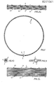
- FIG. 1 shows the view of a ring for a belt
- FIG. 2a shows the top view of a half belt consisting of rings according to FIG. 1
- FIG. 2b shows the top view of the entire belt
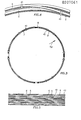
- FIG. 3 shows the view of one of two rings each existing element for a belt
- Fig. 4 is a perspective view of the junction of the two rings running side by side
- Fig. 5 is a plan view of a ring according to FIGS. 3 and 4 existing belt
- Fig. 6 in a diagrammatic representation two adjacent ring parts which are connected to one another by a clip
- Fig. 7 the clip and in Fig. 8 the circuit board for producing the clip
- Fig. 9 in an enlarged view 1
- FIG. 11 the cross section of a finished tire with the tire width after offset radial reinforcements
- FIG. 12 a cross section through the side wall of the tire according to FIG. 11
- FIG. 13 a 14 shows the view of an end loop of the radial armoring element according to FIG. 13 in the direction of arrow XIV
- FIG. 15 shows a cross section
- FIGS. 16 and 17 show views of an anchoring element
- FIGS. 18, 19 and 20 likewise Cross section and views of a variant of the anchoring element
- FIG. 21 shows a cross section similar to FIG. 11 of a somewhat modified embodiment
- FIGS. 23 and 24 views in two mutually perpendicular directions of a spacer
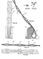
- FIGS. 25 and 26 views of a variant of a prefabricated radial element
- FIGS. 27 and FIG. 28 views of a split pin
- FIGS. 29 and 30 are views of a further embodiment.
- the belt of a vehicle tire consists of individual rings 1 running next to one another, which are each formed from a spirally wound flat wire.
- the ends 2 and 3 of the flat wire are bent over and held by a simple clip 4.
- FIG. 9 the part of the ring 1 provided with the holding clip 4 is drawn out enlarged and in FIG. 10 the holding clip 4 is shown.
- the elements of a belt according to FIGS. 3 to 5 each consist of two adjacent rings 5 and 6. These rings 5 and 6 are spirally wound from a single flat wire, the beginning 7 of the wire beginning inside the ring its outer circumference extends with the section 8 to the ring 5 and ends with the end 9 in the interior of the ring 5. Holding clips 10 are arranged in the area of the section 8.
- retaining clips 11 instead of the retaining clips 10, retaining clips 11 according to FIGS. 6 to 8 can also be used. These holding clips 11 have a central web 12, from which tabs 13, 14 protrude on both sides. These tabs 13, 14 surround the rings 5 and 6, so that a spacing of the two rings 5 and 6 is achieved by means of a retaining clip.
- the rings are provided with spacers 9, which are shown in FIGS. 2a and 2b in connection with the rings and in FIGS. 23 and 24 for themselves are.
- these spacers 19 have grooves 19a for inserting the rings 1, converge conically towards the center of the tire and are directed transversely to the tire axis. This makes it possible to slide one tether according to FIG. 2b from Cer on one side and the other tether from the other side onto the core.
- a radial armature which consists of rings similar to the belt rings described above.
- these rings made of multilayer wound flat wire are formed on one side with open elements 20, at the ends of which loops 21 are formed.
- the elements 20 are folded out fan-shaped from the loops 21.
- Comb-like anchoring elements are provided for anchoring the elements 20, as are shown in particular in FIGS. 15 to 20.
- An anchoring element 22 consists of a base body, from which comb-like projections 23 protrude, a continuous groove 24 being arranged on the underside for inserting a bolt 25. This is inserted through the loops 21 of the elements 20.
- FIG. 11 From Fig. 11 it can be seen that the anchoring elements 22 rest on an anchoring ring 26 and are held by a positioning element 27 screwed thereto.
- the tire designed in this way is mounted in the example on a commercially available three-part rim 28.
- the radial reinforcement elements 20 are also arranged in two groups A, B, which are offset transversely to the tire cross section. From Fig. 12 it follows that the side walls of the tire along the circumference of the individual groups are shaped like waves.
- FIG. 11 also shows a network 29 arranged for spacing in relation to the core.
- the anchoring element 22a according to FIGS. 18 and 20 differs from the anchoring element 22 essentially in that the distance between the comb-like projections 23 is smaller because the radial reinforcement elements 20a are narrower in the area of the loops 21.
- the tire according to FIG. 21 is simpler, but basically constructed in the same way as that according to FIG. 11.
- the main difference is that radial armoring elements 20 lying next to one another are not offset from one another.
- the loops 21 of the radial armoring elements 20 can be held by holding clips. 22, however, it is also possible to use the friction alone to hold the loops. Because the end 29 of the flat wire lies in the region of the loop, the friction around the bolt 25 and the holding element 22 means that the friction is so great that the loop 21 cannot open.
- Both the spacers 19 and the anchoring elements 22 consist of an elastomer, so that they enter into an intimate connection with the material of the tire body 17 after the tire material has hardened and thus a high bond strength is provided.
- the tire material also fills the voids in the loops.
- FIGS. 27 and 28 show variants of the radial armouring in which the flat wires of the armouring run through the interposed shaped pieces in a figure of eight.
- FIG. 28 shows a central section through FIG. 27 without the flat wires placed thereon, the shaped pieces 30 have an elliptical cross section in the region in which the flat wires of the reinforcing elements 20 rest. The deflection of the flat wires is such that this cross section such that a reduction in strength due to this deflection practically does not occur.
- the fittings 30 can also be used to build the radial armature g from individual sections 20 ', 20 "by wrapping the end of each section around a fitting 30'.
Landscapes
- Engineering & Computer Science (AREA)
- Mechanical Engineering (AREA)
- Tires In General (AREA)
- Tyre Moulding (AREA)
Applications Claiming Priority (2)
| Application Number | Priority Date | Filing Date | Title |
|---|---|---|---|
| AT1730/85 | 1985-06-10 | ||
| AT0173085A AT384785B (de) | 1985-06-10 | 1985-06-10 | Fahrzeugreifen |
Publications (2)
| Publication Number | Publication Date |
|---|---|
| EP0207061A2 true EP0207061A2 (fr) | 1986-12-30 |
| EP0207061A3 EP0207061A3 (fr) | 1988-04-20 |
Family
ID=3519766
Family Applications (1)
| Application Number | Title | Priority Date | Filing Date |
|---|---|---|---|
| EP86890163A Withdrawn EP0207061A3 (fr) | 1985-06-10 | 1986-06-04 | Bandage pneumatique pour véhicules |
Country Status (4)
| Country | Link |
|---|---|
| US (1) | US4702294A (fr) |
| EP (1) | EP0207061A3 (fr) |
| JP (1) | JPS6250204A (fr) |
| AT (1) | AT384785B (fr) |
Families Citing this family (5)
| Publication number | Priority date | Publication date | Assignee | Title |
|---|---|---|---|---|
| US5082713A (en) * | 1990-07-23 | 1992-01-21 | Pirelli Armstrong Tire Corporation | Wide monofilament reinforcing cords employing high performance thermoplastics and tire belts made therefrom |
| US5660656A (en) * | 1992-08-05 | 1997-08-26 | Sedepro | Tire with anchored carcass |
| FR2717425A1 (fr) * | 1994-03-16 | 1995-09-22 | Michelin & Cie | Enveloppe de pneumatique dépourvue de tringle. |
| FR2921863B1 (fr) * | 2007-10-05 | 2009-12-18 | Michelin Soc Tech | Pneumatique utilisant une structure de renfort a fibres de section aplatie |
| JP6482590B2 (ja) * | 2016-04-01 | 2019-03-13 | 矢崎総業株式会社 | ワイヤハーネス |
Family Cites Families (9)
| Publication number | Priority date | Publication date | Assignee | Title |
|---|---|---|---|---|
| GB225477A (en) * | 1924-06-24 | 1924-12-04 | American Chain & Cable Co | Improvements in or relating to wire cables |
| DE1034495B (de) * | 1955-01-15 | 1958-07-17 | Pirelli | Ringfoermige, gegen Zugbeanspruchungen widerstandsfaehige Luftreifeneinlage |
| DE1043843B (de) * | 1955-01-15 | 1958-11-13 | Pirelli | Ringfoermige Einlage fuer Luftreifen fuer Fahrzeugraeder |
| US2987095A (en) * | 1958-10-10 | 1961-06-06 | Ohio Commw Eng Co | Tire cord structure |
| LU65416A1 (fr) * | 1971-05-26 | 1973-01-22 | ||
| US3794097A (en) * | 1972-11-02 | 1974-02-26 | Goodyear Tire & Rubber | Pneumatic tire |
| US4011899A (en) * | 1975-02-19 | 1977-03-15 | Monsanto Company | Steel member for reinforcing rubber compositions and method of making same |
| US4428411A (en) * | 1982-08-23 | 1984-01-31 | Grumman Aerospace Corporation | Run-flat tire and method of making same |
| DE3317712C2 (de) * | 1983-05-16 | 1986-10-30 | Akzo Gmbh, 5600 Wuppertal | Verstärkungscord zur Verstärkung von elastomeren Erzeugnissen |
-
1985
- 1985-06-10 AT AT0173085A patent/AT384785B/de not_active IP Right Cessation
-
1986
- 1986-03-07 US US06/837,508 patent/US4702294A/en not_active Expired - Fee Related
- 1986-06-04 EP EP86890163A patent/EP0207061A3/fr not_active Withdrawn
- 1986-06-10 JP JP61132927A patent/JPS6250204A/ja active Pending
Also Published As
| Publication number | Publication date |
|---|---|
| AT384785B (de) | 1988-01-11 |
| JPS6250204A (ja) | 1987-03-04 |
| ATA173085A (de) | 1987-06-15 |
| US4702294A (en) | 1987-10-27 |
| EP0207061A3 (fr) | 1988-04-20 |
Similar Documents
| Publication | Publication Date | Title |
|---|---|---|
| DE68906064T2 (de) | Luftreifen. | |
| DE2932853C3 (de) | Gliederbreitkeilriemen | |
| DE2214553A1 (de) | Autoreifen | |
| DE2363250C3 (de) | Axial nachgiebige, vorzugsweise einstückige Wickelhülse für Garne | |
| DE3000351A1 (de) | Durch draht- oder fasereinlage verstaerkter schlauch und verfahren zu dessen herstellung | |
| DE2735881A1 (de) | Fahrzeugluftreifen mit guertelartiger verstaerkung | |
| EP0669051B1 (fr) | Machine electrique polyphasee comportant des tiges pour encoches coaxiales | |
| EP0350732B1 (fr) | Câble formé, élité | |
| DE2757965A1 (de) | Schubuebertragungselement und verfahren zu dessen herstellung | |
| EP0622251B1 (fr) | Bandage non-pneumatique | |
| DE2026874B2 (de) | Wulstkern fuer fahrzeugluftreifen | |
| DE4212846C2 (de) | Verstärkungscord für elastomere Erzeugnisse | |
| EP0129183A2 (fr) | Procédé pour la fabrication d'un bandage pneumatique à bourrelet renforcé | |
| EP0207061A2 (fr) | Bandage pneumatique pour véhicules | |
| EP0444077B1 (fr) | Bigoudi | |
| DE1910011A1 (de) | Verfahren zur Herstellung eines Lichtleiters | |
| AT394158B (de) | Fahrzeugreifen | |
| EP0292700B1 (fr) | Tissu en hélices combinées | |
| DE9207598U1 (de) | Armierungsfaser aus Stahldraht | |
| DE2543579C3 (de) | Streckwerks-Walzenbezug | |
| DE2832495C2 (de) | Bewehrungsfaser und Vorrichtung zur Herstsellung der Bewehrungsfaser | |
| DE2804251A1 (de) | Schlauch, insbesondere staubsaugerschlauch und verfahren zu seiner herstellung | |
| DE10014357C2 (de) | Hydraulikleitung für Kraftfahrzeuge | |
| DE2505741B2 (de) | Wulstkern für Fahrzeugluftreifen | |
| AT210772B (de) | Luftreifendecke mit im Bereich der Lauffläche angeordneter Verstärkungseinlage |
Legal Events
| Date | Code | Title | Description |
|---|---|---|---|
| PUAI | Public reference made under article 153(3) epc to a published international application that has entered the european phase |
Free format text: ORIGINAL CODE: 0009012 |
|
| AK | Designated contracting states |
Kind code of ref document: A2 Designated state(s): AT BE CH DE FR GB IT LI LU NL SE |
|
| PUAL | Search report despatched |
Free format text: ORIGINAL CODE: 0009013 |
|
| AK | Designated contracting states |
Kind code of ref document: A3 Designated state(s): AT BE CH DE FR GB IT LI LU NL SE |
|
| STAA | Information on the status of an ep patent application or granted ep patent |
Free format text: STATUS: THE APPLICATION IS DEEMED TO BE WITHDRAWN |
|
| 18D | Application deemed to be withdrawn |
Effective date: 19881021 |