EP0207191B1 - Bague d'étanchéité à boîtier - Google Patents
Bague d'étanchéité à boîtier Download PDFInfo
- Publication number
- EP0207191B1 EP0207191B1 EP85112839A EP85112839A EP0207191B1 EP 0207191 B1 EP0207191 B1 EP 0207191B1 EP 85112839 A EP85112839 A EP 85112839A EP 85112839 A EP85112839 A EP 85112839A EP 0207191 B1 EP0207191 B1 EP 0207191B1
- Authority
- EP
- European Patent Office
- Prior art keywords
- flange
- sleeve
- shaft
- cassette seal
- spindle
- Prior art date
- Legal status (The legal status is an assumption and is not a legal conclusion. Google has not performed a legal analysis and makes no representation as to the accuracy of the status listed.)
- Expired
Links
Images

Classifications
-
- F—MECHANICAL ENGINEERING; LIGHTING; HEATING; WEAPONS; BLASTING
- F16—ENGINEERING ELEMENTS AND UNITS; GENERAL MEASURES FOR PRODUCING AND MAINTAINING EFFECTIVE FUNCTIONING OF MACHINES OR INSTALLATIONS; THERMAL INSULATION IN GENERAL
- F16J—PISTONS; CYLINDERS; SEALINGS
- F16J15/00—Sealings
- F16J15/16—Sealings between relatively-moving surfaces
- F16J15/32—Sealings between relatively-moving surfaces with elastic sealings, e.g. O-rings
- F16J15/3248—Sealings between relatively-moving surfaces with elastic sealings, e.g. O-rings provided with casings or supports
- F16J15/3252—Sealings between relatively-moving surfaces with elastic sealings, e.g. O-rings provided with casings or supports with rigid casings or supports
- F16J15/3256—Sealings between relatively-moving surfaces with elastic sealings, e.g. O-rings provided with casings or supports with rigid casings or supports comprising two casing or support elements, one attached to each surface, e.g. cartridge or cassette seals
Definitions
- the invention relates to a cassette seal, consisting of an outer ring secured against rotation in the receiving bore with an inwardly facing hollow conical ring projection and an inner ring secured against rotation on the shaft or axis with two flanges axially encompassing the ring projection.
- DE-PS 33 25 201 refers to a cassette seal of the aforementioned type. At very low manufacturing costs, it is generally characterized by a sealing result while avoiding adjustment work before it is started up, even if radial displacements, axial displacements and / or angular displacements of the sealed shaft are to be expected. However, when used in mass production, there are occasional outliers in these properties, which is unsatisfactory.
- the invention has for its object to develop a cassette seal of the type mentioned in such a way that the occurrence of corresponding outliers is safely avoided without accepting other functional disadvantages.
- the cassette seal should be available at low cost.
- the cassette seal can be designed based on that according to DEPS 33 25 201.
- the flange which contacts the hollow-conical ring projection of the outer ring on the inside is always extended to form a sleeve, which in turn is supported on the surface, the sealed shaft or axis.
- the flange and the sleeve are connected in the area of their largest diameter.
- the sleeve and the flange can have essentially the same wall thickness, which results in a hermetically sealed cavity between the two points at which the surface of the sealed shaft or rod is touched by the resting inner ring. Its presence contributes significantly to achieving a good static seal in this area. Sealed medium, mostly oil, cannot pass through the cassette seal in the area of the surface of the sealed shaft or axis.
- the points of the inner ring bearing against the shaft or axis can be dimensioned very short in the axial direction and, if necessary, can be limited by intersecting conical surfaces without impairing good guidance of the inner ring. In terms of material, savings can be achieved in this way, which is why the cassette seal according to the invention does not easily have a noteworthy increase in price compared to one according to DE-PS 33 25 201.
- the sleeve can rest on an inwardly projecting annular surface of the outer ring on the side facing away from the annular projection of the flange.
- this area there is thus a further dynamic sealing zone which additionally supplements the series of dynamic sealing zones which already exist in this regard.
- the achievable sealing result shows a corresponding improvement.
- the outer ring of the cassette seal proposed according to the invention should consist of a material that is as strong as possible, and in addition to metallic materials, plastics can also be taken into consideration, in particular those with favorable sliding properties, such as PTFE.
- the inner ring is protected from mechanical damage by the outer ring. Considerations in this regard can therefore be taken into account when training the Inner ring are largely ignored.
- the focus of his training is on ensuring the pressure required in this area between the opposing parts.
- the use of rubber-elastic materials has increased. proven excellent.
- the flange contacting the hollow conical ring projection of the outer ring on the inside can be provided with recesses which are uniformly distributed on the circumference and open axially and radially outwards. This improves the dynamic sealing effect in this area, in particular if the flange faces the side of the medium to be sealed.
- the sleeve and the flange have a hollow cone and have an opposite direction of inclination. Both parts can be assigned to each other in mirror image.
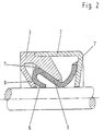
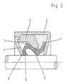
- the externally visible parts of the outer ring essentially consist of a cap 2 made of sheet steel, into which the part carrying the ring projection 3 is inserted axially.
- the latter consists of PTFE or a related plastic.
- the recess enclosed by the ring projection 3 is additionally closed by a cover 4 in the embodiment according to FIG. 3.
- the latter also consists of PTFE or a related material and is liquid-tight and secured against rotation on the part bearing in the annular projection 3 and thus on the cap 2.
- the inner rings used are made of rubber-elastic material with a Shore A and 65 hardness. They rest with the flange 5 under an elastic prestress on the inside of the ring projection 3, which is otherwise axially encompassed to form a further, dynamic sealing zone.
- the flange 5 merges smoothly into the sleeve 6 in the area of its largest outer diameter. which in turn is supported on the surface of the sealed shaft or axle.
- the cuff 6 is assigned to the inner ring in a mirror image, whereby a particularly good guiding effect is achieved.
- the sleeve is rolled in the area touching the surface of the sealed shaft or axis in the direction of the flange 5, whereby, in addition to good guidance, an improved flexibility of the inner ring is achieved.
- the inner ring has, in all versions, projections 7 which are distributed uniformly on the circumference and extend in the radial and axial directions.
- the annular space between the cap 2, the ring projection 3 and the inner ring in the embodiment according to FIG. 3 is filled with a lubricant, advantageously with colloidal graphite.
Landscapes
- Engineering & Computer Science (AREA)
- General Engineering & Computer Science (AREA)
- Mechanical Engineering (AREA)
- Sealing Devices (AREA)
- Semiconductor Lasers (AREA)
- Measurement Of Radiation (AREA)
- Encapsulation Of And Coatings For Semiconductor Or Solid State Devices (AREA)
- Gasket Seals (AREA)
- Liquid Crystal (AREA)
- Sealing With Elastic Sealing Lips (AREA)
Claims (7)
Priority Applications (1)
| Application Number | Priority Date | Filing Date | Title |
|---|---|---|---|
| AT85112839T ATE41987T1 (de) | 1985-06-04 | 1985-10-10 | Kassettendichtung. |
Applications Claiming Priority (2)
| Application Number | Priority Date | Filing Date | Title |
|---|---|---|---|
| DE3519966A DE3519966C1 (de) | 1985-06-04 | 1985-06-04 | Kassettendichtung |
| DE3519966 | 1985-06-04 |
Publications (3)
| Publication Number | Publication Date |
|---|---|
| EP0207191A2 EP0207191A2 (fr) | 1987-01-07 |
| EP0207191A3 EP0207191A3 (en) | 1987-11-11 |
| EP0207191B1 true EP0207191B1 (fr) | 1989-04-05 |
Family
ID=6272387
Family Applications (1)
| Application Number | Title | Priority Date | Filing Date |
|---|---|---|---|
| EP85112839A Expired EP0207191B1 (fr) | 1985-06-04 | 1985-10-10 | Bague d'étanchéité à boîtier |
Country Status (4)
| Country | Link |
|---|---|
| EP (1) | EP0207191B1 (fr) |
| AT (1) | ATE41987T1 (fr) |
| DE (2) | DE3519966C1 (fr) |
| ES (1) | ES290349Y (fr) |
Families Citing this family (2)
| Publication number | Priority date | Publication date | Assignee | Title |
|---|---|---|---|---|
| US7025357B2 (en) * | 2001-06-08 | 2006-04-11 | Freudenberg-Nok General Partnership | Shaft seal having lip supports |
| DE10312050A1 (de) * | 2003-03-18 | 2004-10-07 | Spicer Gelenkwellenbau Gmbh & Co. Kg | Abdichtanordnung für den Längenausgleich einer Kreuzgelenkwelle |
Family Cites Families (3)
| Publication number | Priority date | Publication date | Assignee | Title |
|---|---|---|---|---|
| DE3237638C2 (de) * | 1982-10-11 | 1984-09-20 | Fa. Carl Freudenberg, 6940 Weinheim | Wellendichtung |
| DE3320855C1 (de) * | 1983-06-09 | 1984-08-16 | Fa. Carl Freudenberg, 6940 Weinheim | Dichtung |
| DE3325201C1 (de) * | 1983-07-13 | 1984-05-24 | Fa. Carl Freudenberg, 6940 Weinheim | Dichtung |
-
1985
- 1985-06-04 DE DE3519966A patent/DE3519966C1/de not_active Expired
- 1985-10-10 AT AT85112839T patent/ATE41987T1/de not_active IP Right Cessation
- 1985-10-10 EP EP85112839A patent/EP0207191B1/fr not_active Expired
- 1985-10-10 DE DE8585112839T patent/DE3569281D1/de not_active Expired
- 1985-11-15 ES ES1985290349U patent/ES290349Y/es not_active Expired
Also Published As
| Publication number | Publication date |
|---|---|
| DE3519966C1 (de) | 1986-07-24 |
| DE3569281D1 (en) | 1989-05-11 |
| EP0207191A2 (fr) | 1987-01-07 |
| EP0207191A3 (en) | 1987-11-11 |
| ES290349Y (es) | 1987-01-16 |
| ATE41987T1 (de) | 1989-04-15 |
| ES290349U (es) | 1986-05-16 |
Similar Documents
| Publication | Publication Date | Title |
|---|---|---|
| EP0157904B1 (fr) | Joint pour cassettes | |
| EP0230503B1 (fr) | Joint à lèvre | |
| EP0133928B1 (fr) | Joint pour arbre rotatif | |
| EP0123724B1 (fr) | Joint | |
| DE3204989C2 (de) | Kassettendichtung | |
| EP0082239B1 (fr) | Joint d'étanchéité radial d'arbre | |
| EP0135646B1 (fr) | Accouplement en caoutchouc | |
| EP0357875A2 (fr) | Garniture étanche de l'arbre | |
| EP0980998A2 (fr) | Joint à lèvre radiale | |
| EP1041318B1 (fr) | Bague d'étanchéité | |
| EP0362468A1 (fr) | Joint à lèvre | |
| EP0266479B1 (fr) | Amortisseur d'oscillations de torsion à anneau de serrage intégré | |
| EP0212041A1 (fr) | Volant | |
| EP1026428A2 (fr) | Bague d'étanchéité | |
| EP0137092B1 (fr) | Joint d'étanchéité pour arbre | |
| EP0798498A1 (fr) | Joint à lèvre radiale avec effet de refoulement indépendant du sens de rotation | |
| EP0156942B1 (fr) | Joint | |
| EP0207191B1 (fr) | Bague d'étanchéité à boîtier | |
| EP0187891B1 (fr) | Bague d'étanchéité à lèvre | |
| DE3501334C1 (de) | Dichtung | |
| EP0086953B1 (fr) | Joint d'arbe | |
| DE3221526A1 (de) | Wellendichtring | |
| DE3320855C1 (de) | Dichtung | |
| DE102004020965B4 (de) | Radialwellendichtring | |
| EP0242431A2 (fr) | Joint torique |
Legal Events
| Date | Code | Title | Description |
|---|---|---|---|
| PUAI | Public reference made under article 153(3) epc to a published international application that has entered the european phase |
Free format text: ORIGINAL CODE: 0009012 |
|
| AK | Designated contracting states |
Kind code of ref document: A2 Designated state(s): AT BE DE FR GB IT NL SE |
|
| PUAL | Search report despatched |
Free format text: ORIGINAL CODE: 0009013 |
|
| AK | Designated contracting states |
Kind code of ref document: A3 Designated state(s): AT BE DE FR GB IT NL SE |
|
| 17P | Request for examination filed |
Effective date: 19871015 |
|
| 17Q | First examination report despatched |
Effective date: 19880721 |
|
| ITF | It: translation for a ep patent filed | ||
| GRAA | (expected) grant |
Free format text: ORIGINAL CODE: 0009210 |
|
| AK | Designated contracting states |
Kind code of ref document: B1 Designated state(s): AT BE DE FR GB IT NL SE |
|
| REF | Corresponds to: |
Ref document number: 41987 Country of ref document: AT Date of ref document: 19890415 Kind code of ref document: T |
|
| GBT | Gb: translation of ep patent filed (gb section 77(6)(a)/1977) | ||
| REF | Corresponds to: |
Ref document number: 3569281 Country of ref document: DE Date of ref document: 19890511 |
|
| ET | Fr: translation filed | ||
| PLBE | No opposition filed within time limit |
Free format text: ORIGINAL CODE: 0009261 |
|
| STAA | Information on the status of an ep patent application or granted ep patent |
Free format text: STATUS: NO OPPOSITION FILED WITHIN TIME LIMIT |
|
| 26N | No opposition filed | ||
| ITTA | It: last paid annual fee | ||
| PGFP | Annual fee paid to national office [announced via postgrant information from national office to epo] |
Ref country code: GB Payment date: 19940922 Year of fee payment: 10 |
|
| PGFP | Annual fee paid to national office [announced via postgrant information from national office to epo] |
Ref country code: SE Payment date: 19940923 Year of fee payment: 10 |
|
| PGFP | Annual fee paid to national office [announced via postgrant information from national office to epo] |
Ref country code: DE Payment date: 19940928 Year of fee payment: 10 |
|
| PGFP | Annual fee paid to national office [announced via postgrant information from national office to epo] |
Ref country code: AT Payment date: 19941011 Year of fee payment: 10 |
|
| PGFP | Annual fee paid to national office [announced via postgrant information from national office to epo] |
Ref country code: FR Payment date: 19941013 Year of fee payment: 10 |
|
| PGFP | Annual fee paid to national office [announced via postgrant information from national office to epo] |
Ref country code: NL Payment date: 19941031 Year of fee payment: 10 |
|
| PGFP | Annual fee paid to national office [announced via postgrant information from national office to epo] |
Ref country code: BE Payment date: 19941108 Year of fee payment: 10 |
|
| EAL | Se: european patent in force in sweden |
Ref document number: 85112839.7 |
|
| PG25 | Lapsed in a contracting state [announced via postgrant information from national office to epo] |
Ref country code: DE Effective date: 19950314 |
|
| PG25 | Lapsed in a contracting state [announced via postgrant information from national office to epo] |
Ref country code: GB Effective date: 19951010 Ref country code: AT Effective date: 19951010 |
|
| PG25 | Lapsed in a contracting state [announced via postgrant information from national office to epo] |
Ref country code: SE Effective date: 19951011 |
|
| PG25 | Lapsed in a contracting state [announced via postgrant information from national office to epo] |
Ref country code: BE Effective date: 19951031 |
|
| BERE | Be: lapsed |
Owner name: FIRMA CARL FREUDENBERG Effective date: 19951031 |
|
| PG25 | Lapsed in a contracting state [announced via postgrant information from national office to epo] |
Ref country code: NL Effective date: 19960501 |
|
| GBPC | Gb: european patent ceased through non-payment of renewal fee |
Effective date: 19951010 |
|
| PG25 | Lapsed in a contracting state [announced via postgrant information from national office to epo] |
Ref country code: FR Effective date: 19960628 |
|
| EUG | Se: european patent has lapsed |
Ref document number: 85112839.7 |
|
| NLV4 | Nl: lapsed or anulled due to non-payment of the annual fee |
Effective date: 19960501 |
|
| REG | Reference to a national code |
Ref country code: FR Ref legal event code: ST |