EP0207207B1 - Appareil pour l'élimination des spores butyriques du lait par crémage - Google Patents
Appareil pour l'élimination des spores butyriques du lait par crémage Download PDFInfo
- Publication number
- EP0207207B1 EP0207207B1 EP19850401326 EP85401326A EP0207207B1 EP 0207207 B1 EP0207207 B1 EP 0207207B1 EP 19850401326 EP19850401326 EP 19850401326 EP 85401326 A EP85401326 A EP 85401326A EP 0207207 B1 EP0207207 B1 EP 0207207B1
- Authority
- EP
- European Patent Office
- Prior art keywords
- cups
- vat
- vertical tube
- milk
- collecting device
- Prior art date
- Legal status (The legal status is an assumption and is not a legal conclusion. Google has not performed a legal analysis and makes no representation as to the accuracy of the status listed.)
- Expired
Links
- 239000008267 milk Substances 0.000 title claims description 9
- 235000013336 milk Nutrition 0.000 title claims description 9
- 210000004080 milk Anatomy 0.000 title claims description 9
- FERIUCNNQQJTOY-UHFFFAOYSA-N Butyric acid Chemical compound CCCC(O)=O FERIUCNNQQJTOY-UHFFFAOYSA-N 0.000 title 2
- 239000006071 cream Substances 0.000 claims description 10
- 235000013351 cheese Nutrition 0.000 description 4
- 239000007788 liquid Substances 0.000 description 4
- 238000004519 manufacturing process Methods 0.000 description 4
- 239000006228 supernatant Substances 0.000 description 4
- 230000008030 elimination Effects 0.000 description 3
- 238000003379 elimination reaction Methods 0.000 description 3
- 238000000034 method Methods 0.000 description 3
- 240000002129 Malva sylvestris Species 0.000 description 2
- 235000006770 Malva sylvestris Nutrition 0.000 description 2
- 238000010908 decantation Methods 0.000 description 2
- 239000012530 fluid Substances 0.000 description 2
- 238000012986 modification Methods 0.000 description 2
- 230000004048 modification Effects 0.000 description 2
- 241000283690 Bos taurus Species 0.000 description 1
- 238000013019 agitation Methods 0.000 description 1
- 235000013365 dairy product Nutrition 0.000 description 1
- 230000037213 diet Effects 0.000 description 1
- 235000005911 diet Nutrition 0.000 description 1
- 238000000855 fermentation Methods 0.000 description 1
- 230000004151 fermentation Effects 0.000 description 1
- 239000000463 material Substances 0.000 description 1
- 239000000047 product Substances 0.000 description 1
- 238000003303 reheating Methods 0.000 description 1
- 230000000284 resting effect Effects 0.000 description 1
- 230000000717 retained effect Effects 0.000 description 1
- 239000004460 silage Substances 0.000 description 1
- 238000005406 washing Methods 0.000 description 1
Images

Classifications
-
- A—HUMAN NECESSITIES
- A01—AGRICULTURE; FORESTRY; ANIMAL HUSBANDRY; HUNTING; TRAPPING; FISHING
- A01J—MANUFACTURE OF DAIRY PRODUCTS
- A01J11/00—Apparatus for treating milk
- A01J11/10—Separating milk from cream
- A01J11/12—Appliances for removing cream
Definitions
- the present invention relates to the elimination of butyric spores from milk for its use in the manufacture of cheeses.
- the object of the present invention is to provide an apparatus allowing a thorough elimination of concentrated butyric spores in a relatively small volume of supernatant.
- the device which is the subject of the present invention consisting of a cylindrical tank with a vertical axis, is characterized in that it comprises a collecting device constituted by a plurality of cups regularly distributed over the straight section of the tank, at the same level, and supported by tubular arms fixed on an upper vertical tube telescopically arranged in a fixed lower vertical tube, said tubular arms connecting said cups to the upper vertical tube to allow the evacuation by said tubes of the cream collected by the cups, and a mechanism allowing to modify the height position of the cups in the tank.
- the collecting device may further comprise a central cup fixed directly to the upper vertical tube.
- the collecting device may, for example, be suspended from the cable of a lifting system mounted on the cover of the tank.
- the wall of the tank may advantageously include, in its upper part, heat exchange means making it possible to bring the supernatant phase to a suitable temperature, after decantation and to prevent the fatty materials from remaining stuck to the wall, these means may include a coil or a double envelope where a fluid will be circulated at the desired temperature.
- the apparatus shown in the drawings consists of a closed cylindrical tank 10, with a vertical axis and a circular section provided with a bottom 12 and a conical cover 14; it comprises at its base a skirt 16 resting on the ground by means of load cells 18.
- a coil 19 fixed externally on the upper part of the tank makes it possible to bring, after decantation, the supernatant phase to suitable temperature by circulation of a reheating fluid and to prevent the fat from sticking to the wall of the tank.
- This tank is equipped with a device allowing the overflowing cream to be collected and evacuated when the milk contained in the tank has been left to stand for a certain time.
- This device consists of a series of cups mounted on a vertical tube 20 arranged in the axis of the tank and arranged telescopically in a vertical tube 22 fixed on the bottom of the tank.
- the vertical tube 22 is also supported by tie rods 24 attached to the cover of the tank.
- the central cup 26 is fixed directly to the tube 20, coaxially with the latter, and holes drilled in the tube, near the bottom of the cup, allow the evacuation of the liquid collected by the cup.
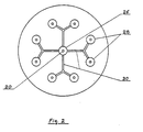
- Eight other cups 28 are arranged around the axis of the tank, away from the latter and from the wall of the tank and supported by four tubular arms 30 connected to the tube 20 by means of a sleeve 32 At their ends, the arms 30 divide into two branches, each of which supports a cup. These branches are provided at their end with a horizontal flange on which is fixed a flange provided on the bottom of the cup around. a central opening allowing the evacuation of the liquid collected by the cups towards the tube 20, through the tubular arms 30.
- the cups 26 are also supported by shrouds 34 attached to the upper end of the tube 20 and provided with tensioners . The edges of all the cups 26 and 28 are located at the same level.
- the collection and evacuation device is suspended from the cover of the tank by means of a cable 36, one end of which is hooked to the tube 20, which passes over a first pulley 38 mounted on the cover and over a second pulley 39 fixed to the end of the rod of a jack 40 and the other end of which is fixed to the cover.
- a cable 36 one end of which is hooked to the tube 20
- the device can be raised and lowered, the tube 20 sliding in the tube 22.
- the tank obviously has a filling opening and a drainage opening and is equi standard washing means; an outlet 42 is also provided at the lower end of the tube 22 for the evacuation of the product collected by the cups.
- the milk After filling the tank, the milk is left to stand for several hours to allow the cream to rise, which causes the butyric spores in its upward movement. During this period, the collecting device is held in the high position so that the edge of the cups is above the level of the free surface of the liquid. At the end of this period, most of the butyric spores are concentrated in the cream which floats. The collecting device is then lowered until the edge of the cups is below the level of the free surface; the cream is poured into the cups and is discharged through the tubes 30, 20 and 22.
- the descent of the collecting device is continuously monitored, which must be slow enough so that the currents which arise in the overlapping part of the liquid mass are not likely to create agitation capable of remixing the cream and milk.
- the collecting device is raised and the milk can then be drawn off.
Landscapes
- Life Sciences & Earth Sciences (AREA)
- Animal Husbandry (AREA)
- Environmental Sciences (AREA)
- Dairy Products (AREA)
Description
- La présente invention concerne l'élimination des spores butyriques du lait pour son utilisation dans la fabrication des fromages.
- Les accidents de fabrication de certains fromages dus à la fermentation butyrique créent un préjudice économique de plus en plus important à l'industrie fromagère par suite du développement considérable de l'utilisation de l'ensilage dans l'alimentation des vaches laitières. Parmi les procédés utilisés pour éliminer les spores butyriques, le crémage présente l'avantage d'être relativement peu coûteux à mettre en oeuvre. Ce procédé, qui est décrit dans la TECHNIQUE LAI-TIERE n° 939 de Janvier 1980, p. 37, est basé sur la constatation que la crème en remontant entraîne avec elle une partie importante des spores butyriques ; il consiste à laisser reposer le lait pendant plusieurs heures dans une cuve puis à soutirer environ 80 à 85 % du lait qui est envoyé en fabrication, la presque totalité des spores butyriques étant retenue dans la partie sumageante. Etant donné que les deux phases ne sont pas nettement séparées, on est conduit par mesure de précaution à avoir une partie surnageante de volume important qui ne peut pas être utilisée en l'état pour la fabrication fromagère et dont l'élimination doit être compensée par un apport de crème « propre ».
- Le but de la présente invention est de fournir un appareil permettant une élimination poussée des spores butyriques concentrées dans un volume de surnageant relativement faible.
- L'appareil objet de la présente invention, constitué par une cuve cylindrique à axe vertical est caractérisé en ce qu'il comprend un dispositif collecteur constitué par une pluralité de coupelles régulièrement réparties sur la section droite de la cuve, à un même niveau, et supportées par des bras tubulaires fixés sur un tube vertical supérieur agencé téléscopiquement dans un tube vertical inférieur fixe, lesdits bras tubulaires reliant lesdites coupelles au tube vertical supérieur pour permettre l'évacuation par lesdits tubes de la crème collectée par les coupelles, et un mécanisme permettant de modifier la position en hauteur des coupelles dans la cuve. Le dispositif collecteur pourra comprendre en outre une coupelle centrale fixée directement sur le tube vertical supérieur. Le dispositif collecteur pourra, par exemple, être suspendu au câble d'un système de levage monté sur le couvercle de la cuve. La paroi de la cuve pourra avantageusement comporter, dans sa partie supérieure, des moyens d'échange thermique permettant de porter la phase surnageante à une température convenable, après décantation et d'éviter que les matières grasses ne restent collées à la paroi, ces moyens pourront comprendre un serpentin ou une double enveloppe où l'on fera circuler un fluide à la température voulue.
- D'autres caractéristiques de l'invention apparaîtront à la lecture de la description qui suit et se réfère aux dessins l'accompagnant qui montrent, à titre d'exemple non limitatif un mode de réalisation de l'invention et sur lesquels :
- La figure 1 montre en élévation et en coupe un appareil conforme à l'invention, et
- La figure 2 est une coupe suivant 2-2 de cet appareil.
- L'appareil représenté sur les dessins est constitué par une cuve fermée cylindrique 10, à axe vertical et à section circulaire munie d'un fond 12 et d'un couvercle 14 coniques ; elle comporte à sa base une jupe 16 reposant sur le sol par l'intermédiaire de pesons 18. Un serpentin 19 fixé extérieurement sur la partie supérieure de la cuve permet d'amener, après décantation, la phase surnageante à température convenable par circulation d'un fluide de réchauffage et d'éviter que les matières grasses ne restent collées à la paroi de la cuve.
- Cette cuve est équipée d'un dispositif permettant de collecter et d'évacuer par débordement la crème qui surnage lorsqu'on a laissé reposer le lait contenu dans la cuve pendant un certain temps. Ce dispositif est constitué par une série de coupelles montées sur un tube vertical 20 disposé dans l'axe de la cuve et agencé téléscopiquement dans un tube vertical 22 fixé sur le fond de la cuve. Le tube vertical 22 est également soutenu par des tirants 24 accrochés au couvercle de la cuve. La coupelle centrale 26 est fixée directement sur le tube 20, coaxialement à celui-ci, et des trous percés dans le tube, près du fond de la coupelle, permettent l'évacuation du liquide collecté par la coupelle. Huit autres coupelles 28 sont disposées autour de l'axe de la cuve, à l'écart de celui-ci et de la paroi de la cuve et supportées par quatre bras tubulaires 30 raccordés au tube 20 par l'intermédiaire d'un manchon 32. A leur extrémité les bras 30 se divisent en deux branches dont chacune supporte une coupelle. Ces branches sont munies à leur extrémité d'une bride horizontale sur laquelle vient se fixer une bride prévue sur le fond de la coupelle autour . d'une ouverture centrale permettant l'évacuation du liquide collecté par les coupelles vers le tube 20, à travers les bras tubulaires 30. Les coupelles 26 sont également soutenues par des haubans 34 accrochés à l'extrémité supérieure du tube 20 et munis de tendeurs. Les bords de toutes les coupelles 26 et 28 sont situés au même niveau.
- Le dispositif de collecte et d'évacuation est suspendu au couvercle de la cuve au moyen d'un câble 36 dont une extrémité est accrochée au tube 20, qui passe sur une première poulie 38 montée sur le couvercle et sur une seconde poulie 39 fixée à l'extrémité de la tige d'un vérin 40 et dont l'autre extrémité est fixée au couvercle. En commandant le vérin 40 on peut faire monter et descendre le dispositif, le tube 20 coulissant dans le tube 22.
- La cuve comporte évidemment un orifice de remplissage et un orifice de vidange et est équipée des moyens de lavage habituels ; une sortie 42 est en outre prévue à l'extrémité inférieure du tube 22 pour l'évacuation du produit collecté par les coupelles.
- Après remplissage de la cuve on laisse reposer le lait pendant plusieurs heures pour laisser remonter la crème qui entraîne dans son mouvement ascendant les spores butyriques. Pendant cette période le dispositif collecteur est maintenu en position haute de telle sorte que le bord des coupelles se trouve au-dessus du niveau de la surface libre du liquide. Au bout de cette période la plus grande partie des spores butyriques est concentrée dans la crème qui surnage. On fait alors descendre le dispositif collecteur jusqu'à ce que le bord des coupelles se trouve au-dessous du niveau de la surface libre ; la crème se déverse dans les coupelles et est évacuée par les tubes 30, 20 et 22. Au moyen du vérin 40 on contrôle en continu la descente du dispositif collecteur qui doit être suffisamment lente pour que les courants qui naissent dans la partie sumageante de la masse liquide ne risquent pas de créer une agitation susceptible de remélanger la crème et le lait. Quant toute la crème est évacuée, on relève le dispositif collecteur et on peut alors soutirer le lait.
- De nombreuses modifications peuvent être apportées à la forme de réalisation décrite, notamment en ce qui concerne la forme, le nombre et la disposition des coupelles, la conception du mécanisme de levage, etc... et il doit être entendu que toutes ces modifications entrent dans le cadre de l'invention, telle que définie par les revendications suivantes.
Claims (4)
Priority Applications (2)
| Application Number | Priority Date | Filing Date | Title |
|---|---|---|---|
| AT85401326T ATE48508T1 (de) | 1985-07-01 | 1985-07-01 | Vorrichtung zum eliminieren von buttersaeuresporen durch entrahmen der milch. |
| DE8585401326T DE3574663D1 (de) | 1985-07-01 | 1985-07-01 | Vorrichtung zum eliminieren von buttersaeuresporen durch entrahmen der milch. |
Applications Claiming Priority (1)
| Application Number | Priority Date | Filing Date | Title |
|---|---|---|---|
| FR8408920A FR2565464B1 (fr) | 1984-06-07 | 1984-06-07 | Appareil pour l'elimination des spores butyriques du lait par cremage |
Publications (2)
| Publication Number | Publication Date |
|---|---|
| EP0207207A1 EP0207207A1 (fr) | 1987-01-07 |
| EP0207207B1 true EP0207207B1 (fr) | 1989-12-13 |
Family
ID=9304801
Family Applications (1)
| Application Number | Title | Priority Date | Filing Date |
|---|---|---|---|
| EP19850401326 Expired EP0207207B1 (fr) | 1984-06-07 | 1985-07-01 | Appareil pour l'élimination des spores butyriques du lait par crémage |
Country Status (2)
| Country | Link |
|---|---|
| EP (1) | EP0207207B1 (fr) |
| FR (1) | FR2565464B1 (fr) |
Families Citing this family (3)
| Publication number | Priority date | Publication date | Assignee | Title |
|---|---|---|---|---|
| FR2595198B1 (fr) * | 1986-03-07 | 1991-12-13 | Chalon Megard Sa | Dispositif de cremage, pour installations de fabrication de fromage |
| IT1288433B1 (it) * | 1997-01-24 | 1998-09-22 | Nuova Maip Macchine Agric | Apparecchiatura per la scrematura statica della panna dal latte |
| FI111902B (fi) * | 2001-06-20 | 2003-10-15 | Piccolo Systems Oy | Menetelmä ja laite raakamaidon käsittelemiseksi |
Family Cites Families (3)
| Publication number | Priority date | Publication date | Assignee | Title |
|---|---|---|---|---|
| DE18542C (de) * | E. Ahlborn, Kommerzienrath in Hildesheim | Neuerungen an Milchaufrahmgefäfsen | ||
| US1512908A (en) * | 1922-12-02 | 1924-10-28 | Cournyer James Herbert | Cream remover |
| US3471673A (en) * | 1968-02-19 | 1969-10-07 | United States Steel Corp | Apparatus for inductively heating a traveling metal slab |
-
1984
- 1984-06-07 FR FR8408920A patent/FR2565464B1/fr not_active Expired
-
1985
- 1985-07-01 EP EP19850401326 patent/EP0207207B1/fr not_active Expired
Also Published As
| Publication number | Publication date |
|---|---|
| FR2565464B1 (fr) | 1986-09-05 |
| EP0207207A1 (fr) | 1987-01-07 |
| FR2565464A1 (fr) | 1985-12-13 |
Similar Documents
| Publication | Publication Date | Title |
|---|---|---|
| EP0207207A1 (fr) | Appareil pour l'élimination des spores butyriques du lait par crémage | |
| FR2506563A1 (fr) | Appareil incubateur pour oeufs de poisson | |
| FR2520972A1 (fr) | Materiel pour la culture par bacs superposes | |
| FI100846B (sv) | Kassump för lagring och uppfödning av fisk | |
| US4331069A (en) | Curd making and separating machine | |
| EP2283722A1 (fr) | Installation agroalimentaire notamment dans la fabrication du fromage | |
| WO1986007524A1 (fr) | Filet d'elevage de poissons | |
| EP0192509B1 (fr) | Procédé et dispositif pour la préparation du lait destiné à la fabrication du fromage | |
| EP0533756A1 (fr) | Pluviometre a reservoir intermediaire | |
| FR2589262A1 (fr) | Procede et dispositif de remplissage d'une cuve | |
| CN107297352B (zh) | 一种中药饮片用清洗装置 | |
| FR2581533A1 (fr) | Procede de lavage de plantes potageres de faible densite et machine de lavage pour la mise en oeuvre du procede | |
| CN208512783U (zh) | 一种稻种水选水洗装置 | |
| FR2744984A1 (fr) | Dispositif permettant de former des lots de portions de denrees alimentaires d'un poids donne | |
| US5370236A (en) | Separator device to separate dense particulate matter from less dense particulate matter | |
| FR2841741A1 (fr) | Dispositif pour l'elevage de mollusques filtreurs en suspension en pleine eau | |
| CN113261431B (zh) | 一种农业生产加工用花生打落设备 | |
| CN210901322U (zh) | 一种葡萄加工脱粒装置 | |
| US402083A (en) | Process of extracting sugar from sorghum by diffusion | |
| FR2682083A1 (fr) | Dispositif automatique pour effectuer la vidange regulee d'une cuve contenant un produit pulverulent, un produit silote, un marc ou des fruits et legumes. | |
| FR2758689A1 (fr) | Appareil pour l'ecremage statique du lait | |
| FR2800570A1 (fr) | Procede et dispositif d'egouttage, de preformage et de tranchage de la calilebotte, pour la fabrication fermiere notamment | |
| WO1990008462A1 (fr) | Procede et installation verticale pour la fabrication en continu de fromage | |
| FR2698103A1 (fr) | Cuve verticale pour le traitement des mouts de raisin. | |
| FR2747271A1 (fr) | Procede pour eliminer des impuretes de legumes, de fruits et analogues, et dispositif mettant en oeuvre ce procede |
Legal Events
| Date | Code | Title | Description |
|---|---|---|---|
| PUAI | Public reference made under article 153(3) epc to a published international application that has entered the european phase |
Free format text: ORIGINAL CODE: 0009012 |
|
| AK | Designated contracting states |
Kind code of ref document: A1 Designated state(s): AT DE IT NL |
|
| 17P | Request for examination filed |
Effective date: 19870423 |
|
| 17Q | First examination report despatched |
Effective date: 19881010 |
|
| GRAA | (expected) grant |
Free format text: ORIGINAL CODE: 0009210 |
|
| AK | Designated contracting states |
Kind code of ref document: B1 Designated state(s): AT DE IT NL |
|
| ITF | It: translation for a ep patent filed | ||
| REF | Corresponds to: |
Ref document number: 48508 Country of ref document: AT Date of ref document: 19891215 Kind code of ref document: T |
|
| REF | Corresponds to: |
Ref document number: 3574663 Country of ref document: DE Date of ref document: 19900118 |
|
| PLBE | No opposition filed within time limit |
Free format text: ORIGINAL CODE: 0009261 |
|
| STAA | Information on the status of an ep patent application or granted ep patent |
Free format text: STATUS: NO OPPOSITION FILED WITHIN TIME LIMIT |
|
| 26N | No opposition filed | ||
| ITTA | It: last paid annual fee | ||
| PGFP | Annual fee paid to national office [announced via postgrant information from national office to epo] |
Ref country code: AT Payment date: 19990618 Year of fee payment: 15 |
|
| PGFP | Annual fee paid to national office [announced via postgrant information from national office to epo] |
Ref country code: NL Payment date: 19990622 Year of fee payment: 15 |
|
| PGFP | Annual fee paid to national office [announced via postgrant information from national office to epo] |
Ref country code: DE Payment date: 19990715 Year of fee payment: 15 |
|
| PG25 | Lapsed in a contracting state [announced via postgrant information from national office to epo] |
Ref country code: AT Free format text: LAPSE BECAUSE OF NON-PAYMENT OF DUE FEES Effective date: 20000701 |
|
| PG25 | Lapsed in a contracting state [announced via postgrant information from national office to epo] |
Ref country code: NL Free format text: LAPSE BECAUSE OF NON-PAYMENT OF DUE FEES Effective date: 20010201 |
|
| NLV4 | Nl: lapsed or anulled due to non-payment of the annual fee |
Effective date: 20010201 |
|
| PG25 | Lapsed in a contracting state [announced via postgrant information from national office to epo] |
Ref country code: DE Free format text: LAPSE BECAUSE OF NON-PAYMENT OF DUE FEES Effective date: 20010501 |