EP0207228A1 - Steuersystem für ein stufenloses Getriebe - Google Patents
Steuersystem für ein stufenloses Getriebe Download PDFInfo
- Publication number
- EP0207228A1 EP0207228A1 EP86104270A EP86104270A EP0207228A1 EP 0207228 A1 EP0207228 A1 EP 0207228A1 EP 86104270 A EP86104270 A EP 86104270A EP 86104270 A EP86104270 A EP 86104270A EP 0207228 A1 EP0207228 A1 EP 0207228A1
- Authority
- EP
- European Patent Office
- Prior art keywords
- transmission ratio
- control
- spool
- control valve
- valve
- Prior art date
- Legal status (The legal status is an assumption and is not a legal conclusion. Google has not performed a legal analysis and makes no representation as to the accuracy of the status listed.)
- Granted
Links
- 230000005540 biological transmission Effects 0.000 title claims abstract description 88
- 230000008859 change Effects 0.000 claims abstract description 5
- 230000001419 dependent effect Effects 0.000 claims description 4
- 238000002485 combustion reaction Methods 0.000 claims 1
- 239000003921 oil Substances 0.000 description 29
- 238000010276 construction Methods 0.000 description 3
- 230000001133 acceleration Effects 0.000 description 2
- 230000003247 decreasing effect Effects 0.000 description 2
- 238000010586 diagram Methods 0.000 description 2
- 230000005484 gravity Effects 0.000 description 2
- 230000007935 neutral effect Effects 0.000 description 2
- 230000009467 reduction Effects 0.000 description 2
- 230000007423 decrease Effects 0.000 description 1
- 230000000994 depressogenic effect Effects 0.000 description 1
- 239000012530 fluid Substances 0.000 description 1
- 239000010687 lubricating oil Substances 0.000 description 1
- 230000007246 mechanism Effects 0.000 description 1
- 230000004048 modification Effects 0.000 description 1
- 238000012986 modification Methods 0.000 description 1
- 239000000843 powder Substances 0.000 description 1
- 230000010349 pulsation Effects 0.000 description 1
- 230000004044 response Effects 0.000 description 1
Images


Classifications
-
- F—MECHANICAL ENGINEERING; LIGHTING; HEATING; WEAPONS; BLASTING
- F16—ENGINEERING ELEMENTS AND UNITS; GENERAL MEASURES FOR PRODUCING AND MAINTAINING EFFECTIVE FUNCTIONING OF MACHINES OR INSTALLATIONS; THERMAL INSULATION IN GENERAL
- F16H—GEARING
- F16H61/00—Control functions within control units of change-speed- or reversing-gearings for conveying rotary motion ; Control of exclusively fluid gearing, friction gearing, gearings with endless flexible members or other particular types of gearing
- F16H61/66—Control functions within control units of change-speed- or reversing-gearings for conveying rotary motion ; Control of exclusively fluid gearing, friction gearing, gearings with endless flexible members or other particular types of gearing specially adapted for continuously variable gearings
- F16H61/662—Control functions within control units of change-speed- or reversing-gearings for conveying rotary motion ; Control of exclusively fluid gearing, friction gearing, gearings with endless flexible members or other particular types of gearing specially adapted for continuously variable gearings with endless flexible members
- F16H61/66254—Control functions within control units of change-speed- or reversing-gearings for conveying rotary motion ; Control of exclusively fluid gearing, friction gearing, gearings with endless flexible members or other particular types of gearing specially adapted for continuously variable gearings with endless flexible members controlling of shifting being influenced by a signal derived from the engine and the main coupling
- F16H61/66259—Control functions within control units of change-speed- or reversing-gearings for conveying rotary motion ; Control of exclusively fluid gearing, friction gearing, gearings with endless flexible members or other particular types of gearing specially adapted for continuously variable gearings with endless flexible members controlling of shifting being influenced by a signal derived from the engine and the main coupling using electrical or electronical sensing or control means
Definitions
- the present invention relates to a control system for an infinitely variable belt-drive automatic transmission for a motor vehicle, and more particularly to a system for controlling the speed of changing the transmission ratio in accordance with driving conditions of the vehicle.
- a known control system for an infinitely variable belt-drive transmission disclosed in United States Patent No. 4,369,675 comprises an endless belt running over a drive pulley and a driven pulley.
- Each pulley comprises a movable conical disc which is axially moved by a fluid operated servo device so as to vary the running diameter of the belt on the pulleys in dependence on driving conditions.
- the system is provided with a line pressure control valve and a transmission ratio control valve.
- Each valve comprises a spool to control the oil supplied to the servo devices.
- the transmission ratio control valve operates to decide the transmission ratio in accordance with the opening degree of a throttle valve of an engine and the speed of the engine.
- the line pressure control valve is adapted to control the line pressure in accordance with the transmission ratio and the engine speed. Output of an engine is transmitted to the drive pulley through a clutch. The line pressure is controlled to prevent the belt from slipping on pulleys in order to transmit the output of the engine.
- the transmission ratio is set at a maximum value.
- the transmission ratio starts to change (to upshift).
- the transmission ratio is automatically and continuously reduced at a speed which is decided by line pressure, pressure of oil supplied to the servo device of the drive pulley, and actual transmission ratio.
- the speed of changing of transmission ratio up to a desired transmission ratio can not be controlled in accordance with driving conditions. Accordingly, hunting or overshoot of transmission ratio occurs, which causes the driveability of the vehicle to reduce.
- Japanese Patent Laid Open 59-159456 discloses a system provided with a first valve for changing the direction of the transmission ratio change and a second valve for controlling the transmission ratio changing speed. By controlling the spool of the second valve, the transmission ratio changing speed is controlled.
- the system is complicated in construction, since two control valves are provided in addition to the conventional system.
- Japanese Patent Laid Open 59-217048 shows a system which operates to vary a desired transmission ratio in accordance with the deviation of an acutal transmission ratio from the desired ratio. However, such a system causes overshoot of the control operation.
- An object of the present invention is to provide a system which may control the transmission ratio changing speed by a single control valve.
- Another object of the present invention is to provide a system which has a fast response thereby preventing the overshoot of the control.
- the transmission ratio control valve has chambers at both ends of the spool, and a solenoid operated on-off control valve is provided for controlling the amount of oil supplied to the chambers of the transmission ratio control valve.
- the system is provided with sensing means for sensing operating conditions of the engine and the transmission and for producing signals dependent on the conditions, a control unit responsive to the signals from the sensing means for producing an output signal for operating the control valve, so that the shifting of the spool is controlled to control the transmission ratio changing speed.
- the infinitely variable belt-drive automatic transmission for a motor vehicle to which the present invention is applied comprises an electromagnetic powder clutch 2 for transmitting the power of an engine 1 to transmission 4 through a selector mechanism 3.
- the belt-drive transmission has a main shaft 5 and an output shaft 6 provided in parallel with the main shaft 5.
- a drive pulley (primary pulley) 7 and a driven pulley (secondary pulley) 8 are mounted on shafts 5 and 6 respectively.
- a fixed conical disc 7b of the drive pulley 7 is integral with main shaft 5 and an axially movable conical disc 7a is axially slidably mounted on the main shaft 5.
- the movable conical disc 7a also slides in a cylinder 9a formed on the main shaft 5 to provide a servo device.
- a chamber 9 of the servo device communicates with a hydraulic circuit 20.
- a fixed conical disc 8b of the driven pulley 8 is formed on the output shaft 6 opposite the movable conical disc 8a having a cylindrical portion which is slidably engaged in a cylinder 6a of the output shaft 6 to form a servo device.
- a chamber 10 of the servo device is also communicated with control circuit 20.
- a drive belt 11 engages with the drive pulley 7 and the driven pulley 8.
- a drive gear 12 Secured to the output shaft 6 is a drive gear 12 which engages with an intermediate reduction gear 13 on an intermediate shaft 14.
- An intermediate gear 15 on the shaft 14 engages with a final gear 16.
- the rotation of the final gear 16 is transmitted to axles 18 of the vehicle driving wheels 19 through a differential 17.
- chamber 9 of the drive pulley 7 is applied with pressurized oil by an oil pump 21 from an oil reservoir 26 passing through a line pressure conduit 22, ports 41a and 41e of a line pressure control valve 40, transmission ratio control valve 50, and conduit 23.
- the chamber 10 of driven pulley 8 is applied with pressurized oil through a passage 22b without passing through valves 40 and 50.
- the movable conical disc 7a of the drive pulley 7 is so designed that the pressure receiving area thereof is larger than that of movable conical disc 8a of the driven pulley 8.
- the line pressure control valve 40 comprises a valve body 41, spool 42, and chambers 41c and 41d.
- the spool 42 is applied with pressure of the pressurized oil in the chamber 41c supplied through a conduit 31.
- the other end of the spool 42 is applied with the pressure of a spring 43 provided between the end of the spool and a retainer 45 the position of which is adjustable by a screw 44.
- the port 41a is communicated with a port 41b of a drain passage 27 in accordance with the position of a land of the spool 42.
- the transmission ratio control valve 50 comprises a valve body 51, spool 52, spring 53 for urging the spool in the downshift direction.
- a port 51b of the valve body 51 is selectively communicated with a pressure oil supply port 51a or a drain port 51c in accordance with the position of lands of spool 52.
- Port 51b communicates with chamber 9 through a conduit 23, and port 51a communicates with line pressure control valve 40 through conduit 22a.
- the drain port 51c is communicated with the oil reservoir 26 through a check valve 25.
- the drain port 41b communicates with oil reservoir 26 through conduit 27 and a lubricating oil pressure providing valve 28.
- the conduit 27 is further communicated with conduit 23 through a check valve 30. A part of the oil in the conduit 27 is supplied to the pulley 8 from a nozzle 29 to lubricate the pulley device.
- the system of the present invention is provided with a regulator supply valve 55, regulator valve 60, solenoid operated on-off control valves 66 and 68.
- the regulator supply valve 55 comprises a valve body 56, spool 57, spring 58 for urging the spool in a direction, port 56a connected to line pressure conduit 22 through passage 35, port 56c connected to drain passage 27 through a passage 36, and end chamber 56d which is communicated with drain passage 27 to be applied with the drain oil pressure opposite the spring 58.
- the line pressure is at a high level, the pressure of drain oil is at a low level because of closing the port 41b of the line pressure control valve 40. In such a state, spool 57 is shifted to the right to communicate port 56a with an output port 56b.
- the regulator valve 60 comprises a valve body 61, spool 62, end chamber 61c, spring 63 urging the spool 62 to the chamber 61c.
- the spool 62 is shifted to the left, so that an inlet port 61a communicates with a drain port 61b to drain the oil.
- a constant pressure of oil is provided in the passage 37.
- the passage 37 is communicated with the chamber 41d of line pressure control valve 40 through a constant pressure passage 38, orifice 65, solenoid operated on-off valve 66, and passage 32 having an accumulator 32a. Further, the passage 38 is communicated with an end chamber 51d of the transmission ratio control valve 50 through a passage 33, and with another end chamber 51e through a passage 34, orifice 67, and solenoid operated on-off valve 68.
- the solenoid operated valve 66 is adapted to be operated by pulses. When energized, a valve 66a opens a drain port 66b. The pulsation of the pressure of oil in the passage 32 is smoothed by orifice 65.
- the solenoid operated valve 68 is the same as valve 66 in construction and operation.
- the control valves 66 and 68 are operated by signals from a control unit 70. Thus, pressure controlled by the control valves 66 and 68 is applied to chambers 41d, 51d and 51e.
- the line pressure Pl is inverse proportion to the control pressure P d .
- pressure receiving area of the spool 52 at chamber 51e is set to a value larger than the area at the chamber 51d.
- the control pressure in the chamber 51e can be changed between a maximum value, which is the same as the constant pressure in the chamber 51d, when the duty ratio is 0% and zero by controlling the duty ratio of pulses for operating the control valve 68.
- the transmission ratio control valve 50 is so arranged that the spool 52 is at a neutral position at a middle duty ratio (for example 50%) and is located in an oil supply position by increasing the duty ratio from the middle duty ratio because of reduction of control pressure in the chamber 51e. Further, the speed of the movement of the spool increases with decreasing of the duty ratio.
- the spool 52 is shifted to an oil drain position by decreasing the duty ratio. It will be understood that when the oil is supplied to the chamber 9, the transmission is upshifted.
- the spring may be omitted.
- Q s a ⁇ S s (Pl-P p )/2
- a c(2g / ⁇ )/2
- P p the pressure in chamber 9
- Pl the line pressure
- C the coefficient for flow rate
- g the acceleration of gravity
- ⁇ the specific gravity of oil
- S s is the opening area of supply port 51a
- S d is the opening area of drain port 51c.
- the duty ratio is decided by the transmission ratio changing speed di/dt and the transmission ratio i.
- the duty ratio D can be obtained from the speed.
- the actual transmission ratio i is larger than the desired transmission ratio id (i>id)
- the value of di/dt is negative.
- the duty ratio D is increased to reduce the pressure in the chamber 51e so as to upshift the transmission.
- the downshift is performed in the reverse manner.
- a drive pulley speed sensor 71, driven pulley speed sensor 72, engine speed sensor 73 and throttle valve position sensor 74 are provided.
- Output signals N s and ⁇ of the throttle valve position sensor 74 are fed to a desired transmission ratio table 76.
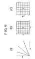
- Fig. 4a shows various actual transmission ratios i and Fig. 4b shows the table 76.
- the desired transmission ratio id is fetched from the table in accordance with the signals N s and ⁇ .
- the speed di/dt and actual ratio i are applied to a duty ratio table 79 to derive the duty ratio D.
- Fig. 4c shows the duty ratio table in which the duty ratio decreases with increases of speed di/dt and ratio i.
- the duty ratio D is supplied to the solenoid operated valve 68 through a driver 80.
- an output signal Ne of the engine speed sensor 73, throttle position signal ⁇ and actual ratio i are fed to a desired line pressure calculator 91 to produce the desired line pressure Pl.
- the desired line pressure Pl is applied to a duty ratio table 92 to derive a duty ratio dependent on the desired line pressure.
- the duty ratio is applied to the solenoid operated valve 66 through a driver 93. The duty ratio is set to increase with increase of the line pressure.
- the line pressure is at the highest value by the pressure control valve 40, since the duty ratio for the valve 66 is large, and the spool 42 of the control valve 40 is at the right end position.
- the desired transmission ratio id and transmission ratio changing speed di/dt are calculated by calculators 76, 78, and duty ratio D is obtained from the table 79.
- the value of the duty ratio D is larger than the neutral value, so that the pressure in the chamber 51d of the control valve 50 is higher than the chamber 51e.
- the spool 52 is shifted to the left to communicate the port 51a with port 51b, so that oil is supplied to the chamber 9 through the conduit 23.
- duty ratio for the control valve 66 is reduced, thereby shifting the spool 42 of the valve 40 to the left.
- the port 41a communicates with the port 41b of the drain passage 27.
- line pressure reduces, and the transmission is upshifted, since oil is still supplied to the chamber 9 through the control valve 50.
- the duty ratio for the control valve 68 becomes large, thereby increasing the transmission changing speed di/dt.
- the opening degree of the throttle valve is reduced for deceleration, the duty ratio is reduced, thereby shifting the spool 52 to the right to drain the chamber 9.
- the transmission is downshifted.
- the transmission changing speed at downshifting increases with reducing of the duty ratio.
- the construction and operation are simplified.
- the spool of the transmission ratio control valve is subjected to control pressures at both ends thereof and shifted by the difference between control pressure. Accordingly, even if the supply oil pressure to be constant changes, the difference does not change, so that exact control operation can be maintained.
Landscapes
- Engineering & Computer Science (AREA)
- General Engineering & Computer Science (AREA)
- Mechanical Engineering (AREA)
- Control Of Transmission Device (AREA)
- Control Of Driving Devices And Active Controlling Of Vehicle (AREA)
Applications Claiming Priority (2)
| Application Number | Priority Date | Filing Date | Title |
|---|---|---|---|
| JP60143461A JPS624954A (ja) | 1985-06-29 | 1985-06-29 | 無段変速機の制御装置 |
| JP143461/85 | 1985-06-29 |
Publications (2)
| Publication Number | Publication Date |
|---|---|
| EP0207228A1 true EP0207228A1 (de) | 1987-01-07 |
| EP0207228B1 EP0207228B1 (de) | 1990-06-20 |
Family
ID=15339241
Family Applications (1)
| Application Number | Title | Priority Date | Filing Date |
|---|---|---|---|
| EP86104270A Expired - Lifetime EP0207228B1 (de) | 1985-06-29 | 1986-03-27 | Steuersystem für ein stufenloses Getriebe |
Country Status (4)
| Country | Link |
|---|---|
| US (1) | US4752277A (de) |
| EP (1) | EP0207228B1 (de) |
| JP (1) | JPS624954A (de) |
| DE (1) | DE3672157D1 (de) |
Families Citing this family (10)
| Publication number | Priority date | Publication date | Assignee | Title |
|---|---|---|---|---|
| JPS5615184A (en) * | 1979-07-17 | 1981-02-13 | Sony Corp | Brushless dc motor |
| JPS63279938A (ja) * | 1987-05-12 | 1988-11-17 | Fuji Heavy Ind Ltd | 無段変速機の油圧制御装置 |
| JP2668851B2 (ja) * | 1988-01-19 | 1997-10-27 | マツダ株式会社 | 無段変速機の制御装置 |
| EP0412758B1 (de) * | 1989-08-09 | 1994-11-02 | Toyota Jidosha Kabushiki Kaisha | Hydraulisches Steuerungssystem eines stufenlosen Keilriemengetriebes mit einer ausfallsicheren Schutzanordnung |
| JP2832283B2 (ja) * | 1990-04-13 | 1998-12-09 | 富士重工業株式会社 | 無段変速機の制御装置 |
| JP2900290B2 (ja) * | 1991-01-22 | 1999-06-02 | 富士重工業株式会社 | 車両用無段変速機の圧力制御装置 |
| US5173084A (en) * | 1991-12-23 | 1992-12-22 | Ford Motor Company | Self-clamping assist for "V" belt continuously variable transmissions |
| JP3411707B2 (ja) * | 1995-03-02 | 2003-06-03 | 本田技研工業株式会社 | ベルト式無段変速機の制御装置 |
| US5776028A (en) * | 1995-09-01 | 1998-07-07 | Honda Giken Kogyo Kabushiki Kaisha | Belt-type continuously variable transmission |
| DE19609787A1 (de) * | 1996-03-13 | 1997-09-18 | Bosch Gmbh Robert | Hydrauliknotsteuerung für ein stufenloses Umschlingungsgetriebe mit erweitertem Handschaltventil |
Citations (6)
| Publication number | Priority date | Publication date | Assignee | Title |
|---|---|---|---|---|
| GB2076084A (en) * | 1980-03-24 | 1981-11-25 | Aisin Warner | Torque ratio control device for a v-belt type continuously variable transmission for vehicles |
| EP0076552A1 (de) * | 1981-10-05 | 1983-04-13 | Van Doorne's Transmissie B.V. | Steuereinrichtung für stufenlos verstellbare Wechselgetriebe |
| EP0107194A1 (de) * | 1982-10-22 | 1984-05-02 | Nissan Motor Co., Ltd. | Steuereinrichtung für stufenlos verstellbares Keilriemengetriebe |
| US4458318A (en) * | 1981-04-24 | 1984-07-03 | Borg-Warner Corporation | Control arrangement for a variable pulley transmission |
| GB2138896A (en) * | 1983-04-29 | 1984-10-31 | Aisin Warner | An automatic transmission for a vehicle |
| GB2145785A (en) * | 1983-08-31 | 1985-04-03 | Fuji Heavy Ind Ltd | A system for controlling the transmission ratio of an infinitely variable belt-drive transmission |
Family Cites Families (10)
| Publication number | Priority date | Publication date | Assignee | Title |
|---|---|---|---|---|
| NL7811192A (nl) * | 1978-11-13 | 1980-05-16 | Doornes Transmissie Bv | Werkwijze en inrichting voor het regelen van een trap- loos variabele transmissie van een motorvoertuig. |
| JPS56160454A (en) * | 1980-05-14 | 1981-12-10 | Aisin Seiki Co Ltd | Velocity ratio control unit for a stepless transmission |
| JPS57161347A (en) * | 1981-03-28 | 1982-10-04 | Nissan Motor Co Ltd | Hydraulic control unit in v-belt stepless speed change gear |
| US4597308A (en) * | 1982-04-19 | 1986-07-01 | Nissan Motor Co., Ltd. | Method and apparatus for controlling reduction ratio of continuously variable transmission |
| EP0092227B1 (de) * | 1982-04-19 | 1988-07-27 | Nissan Motor Co., Ltd. | Verfahren zum Verstellen des Übersetzungsverhältnisses eines stufenlosen Getriebes unter Anpassung der Beschleunigung |
| US4579021A (en) * | 1982-04-30 | 1986-04-01 | Nissan Motor Co., Ltd. | Method and apparatus for controlling line pressure in continuously variable transmission |
| JPS59159456A (ja) * | 1983-02-26 | 1984-09-10 | Toyota Motor Corp | ベルト式無段変速機の油圧装置 |
| US4534243A (en) * | 1983-04-26 | 1985-08-13 | Aisin Warner Kabushiki Kaisha | Hydraulic control system for a V-belt transmission |
| JPH066978B2 (ja) * | 1983-05-20 | 1994-01-26 | トヨタ自動車株式会社 | 車両用無段変速機の制御装置 |
| JPS6057047A (ja) * | 1983-09-09 | 1985-04-02 | Fuji Heavy Ind Ltd | 無段変速機の変速特性制御装置 |
-
1985
- 1985-06-29 JP JP60143461A patent/JPS624954A/ja active Granted
-
1986
- 1986-03-25 US US06/843,962 patent/US4752277A/en not_active Expired - Fee Related
- 1986-03-27 DE DE8686104270T patent/DE3672157D1/de not_active Expired - Lifetime
- 1986-03-27 EP EP86104270A patent/EP0207228B1/de not_active Expired - Lifetime
Patent Citations (6)
| Publication number | Priority date | Publication date | Assignee | Title |
|---|---|---|---|---|
| GB2076084A (en) * | 1980-03-24 | 1981-11-25 | Aisin Warner | Torque ratio control device for a v-belt type continuously variable transmission for vehicles |
| US4458318A (en) * | 1981-04-24 | 1984-07-03 | Borg-Warner Corporation | Control arrangement for a variable pulley transmission |
| EP0076552A1 (de) * | 1981-10-05 | 1983-04-13 | Van Doorne's Transmissie B.V. | Steuereinrichtung für stufenlos verstellbare Wechselgetriebe |
| EP0107194A1 (de) * | 1982-10-22 | 1984-05-02 | Nissan Motor Co., Ltd. | Steuereinrichtung für stufenlos verstellbares Keilriemengetriebe |
| GB2138896A (en) * | 1983-04-29 | 1984-10-31 | Aisin Warner | An automatic transmission for a vehicle |
| GB2145785A (en) * | 1983-08-31 | 1985-04-03 | Fuji Heavy Ind Ltd | A system for controlling the transmission ratio of an infinitely variable belt-drive transmission |
Also Published As
| Publication number | Publication date |
|---|---|
| EP0207228B1 (de) | 1990-06-20 |
| JPH0554581B2 (de) | 1993-08-12 |
| US4752277A (en) | 1988-06-21 |
| JPS624954A (ja) | 1987-01-10 |
| DE3672157D1 (de) | 1990-07-26 |
Similar Documents
| Publication | Publication Date | Title |
|---|---|---|
| EP0207231B1 (de) | Steuersystem für ein stufenlos veränderbares Getriebe | |
| EP0257960B1 (de) | Steuereinrichtung für ein stufenlos regelbares Getriebe | |
| US4803900A (en) | Transmission ratio control system for a continuously variable transmission | |
| US4747325A (en) | Transmission ratio control system for a continuously variable transmission | |
| US4759236A (en) | System for controlling the pressure of oil in a system for a continuously variable transmission | |
| US4708031A (en) | Transmission ratio control system for a continuously variable transmission | |
| EP0214821A1 (de) | Öldruck-Regelsystem für stufenloses Getriebe | |
| US5020392A (en) | Transmission ratio control system for a continuously variable transmission | |
| EP0240282B1 (de) | Steuervorrichtung für den Öldruck eines stufenlos regelbaren Getriebes | |
| EP0207227B1 (de) | Steuersystem für stufenlose Getriebe | |
| US4730518A (en) | System for the transmission ratio of a continuously variable transmission | |
| US4767382A (en) | Transmission ratio control system for a continuously variable transmission | |
| US4721019A (en) | Control system for an infinitely variable transmission | |
| EP0260117A1 (de) | Steuereinrichtung für das Übersetzungsverhältnis für ein stufenlos regelbares Getriebe | |
| EP0258005A1 (de) | Steuervorrichtung für ein stufenlos regelbares Getriebe | |
| US4843913A (en) | Transmission ratio control system for a continuously variable transmission | |
| US4751857A (en) | System for controlling the pressure of oil in a system for an infinitely variable transmission | |
| US4752277A (en) | Control system for an infinitely variable transmission | |
| US4761153A (en) | Transmission ratio control system for a continuously variable transmission | |
| US4819513A (en) | Transmission ratio control system for a continuously variable transmission | |
| US4710151A (en) | System for controlling the pressure of oil in a system for a continuously variable transmission | |
| US4708694A (en) | System for controlling the pressure of oil in a system for a continuously variable transmission |
Legal Events
| Date | Code | Title | Description |
|---|---|---|---|
| PUAI | Public reference made under article 153(3) epc to a published international application that has entered the european phase |
Free format text: ORIGINAL CODE: 0009012 |
|
| AK | Designated contracting states |
Kind code of ref document: A1 Designated state(s): CH DE FR GB IT LI NL |
|
| 17P | Request for examination filed |
Effective date: 19861209 |
|
| 17Q | First examination report despatched |
Effective date: 19880212 |
|
| ITF | It: translation for a ep patent filed | ||
| GRAA | (expected) grant |
Free format text: ORIGINAL CODE: 0009210 |
|
| AK | Designated contracting states |
Kind code of ref document: B1 Designated state(s): CH DE FR GB IT LI NL |
|
| ET | Fr: translation filed | ||
| REF | Corresponds to: |
Ref document number: 3672157 Country of ref document: DE Date of ref document: 19900726 |
|
| PGFP | Annual fee paid to national office [announced via postgrant information from national office to epo] |
Ref country code: GB Payment date: 19910318 Year of fee payment: 6 |
|
| PGFP | Annual fee paid to national office [announced via postgrant information from national office to epo] |
Ref country code: FR Payment date: 19910320 Year of fee payment: 6 |
|
| ITTA | It: last paid annual fee | ||
| PGFP | Annual fee paid to national office [announced via postgrant information from national office to epo] |
Ref country code: NL Payment date: 19910331 Year of fee payment: 6 |
|
| PGFP | Annual fee paid to national office [announced via postgrant information from national office to epo] |
Ref country code: CH Payment date: 19910403 Year of fee payment: 6 |
|
| PLBE | No opposition filed within time limit |
Free format text: ORIGINAL CODE: 0009261 |
|
| STAA | Information on the status of an ep patent application or granted ep patent |
Free format text: STATUS: NO OPPOSITION FILED WITHIN TIME LIMIT |
|
| PGFP | Annual fee paid to national office [announced via postgrant information from national office to epo] |
Ref country code: DE Payment date: 19910429 Year of fee payment: 6 |
|
| 26N | No opposition filed | ||
| PG25 | Lapsed in a contracting state [announced via postgrant information from national office to epo] |
Ref country code: GB Effective date: 19920327 |
|
| PG25 | Lapsed in a contracting state [announced via postgrant information from national office to epo] |
Ref country code: LI Effective date: 19920331 Ref country code: CH Effective date: 19920331 |
|
| PG25 | Lapsed in a contracting state [announced via postgrant information from national office to epo] |
Ref country code: NL Effective date: 19921001 |
|
| NLV4 | Nl: lapsed or anulled due to non-payment of the annual fee | ||
| GBPC | Gb: european patent ceased through non-payment of renewal fee | ||
| PG25 | Lapsed in a contracting state [announced via postgrant information from national office to epo] |
Ref country code: FR Effective date: 19921130 |
|
| REG | Reference to a national code |
Ref country code: CH Ref legal event code: PL |
|
| PG25 | Lapsed in a contracting state [announced via postgrant information from national office to epo] |
Ref country code: DE Effective date: 19921201 |
|
| REG | Reference to a national code |
Ref country code: FR Ref legal event code: ST |
|
| PG25 | Lapsed in a contracting state [announced via postgrant information from national office to epo] |
Ref country code: IT Free format text: LAPSE BECAUSE OF NON-PAYMENT OF DUE FEES;WARNING: LAPSES OF ITALIAN PATENTS WITH EFFECTIVE DATE BEFORE 2007 MAY HAVE OCCURRED AT ANY TIME BEFORE 2007. THE CORRECT EFFECTIVE DATE MAY BE DIFFERENT FROM THE ONE RECORDED. Effective date: 20050327 |