EP0207281A1 - Fusée pour sous-projectiles lancés à partir d'une roquette - Google Patents
Fusée pour sous-projectiles lancés à partir d'une roquette Download PDFInfo
- Publication number
- EP0207281A1 EP0207281A1 EP86107061A EP86107061A EP0207281A1 EP 0207281 A1 EP0207281 A1 EP 0207281A1 EP 86107061 A EP86107061 A EP 86107061A EP 86107061 A EP86107061 A EP 86107061A EP 0207281 A1 EP0207281 A1 EP 0207281A1
- Authority
- EP
- European Patent Office
- Prior art keywords
- striker member
- sub
- fuse
- munition
- slide
- Prior art date
- Legal status (The legal status is an assumption and is not a legal conclusion. Google has not performed a legal analysis and makes no representation as to the accuracy of the status listed.)
- Withdrawn
Links
- 238000006073 displacement reaction Methods 0.000 claims description 10
- 239000000463 material Substances 0.000 claims description 3
- 230000003014 reinforcing effect Effects 0.000 claims description 2
- 230000033001 locomotion Effects 0.000 description 11
- 210000002105 tongue Anatomy 0.000 description 2
- 230000005540 biological transmission Effects 0.000 description 1
- 238000004880 explosion Methods 0.000 description 1
- 239000002184 metal Substances 0.000 description 1
- 230000004048 modification Effects 0.000 description 1
- 238000012986 modification Methods 0.000 description 1
- 230000035515 penetration Effects 0.000 description 1
- 229920003023 plastic Polymers 0.000 description 1
- 239000004033 plastic Substances 0.000 description 1
Images

Classifications
-
- F—MECHANICAL ENGINEERING; LIGHTING; HEATING; WEAPONS; BLASTING
- F42—AMMUNITION; BLASTING
- F42C—AMMUNITION FUZES; ARMING OR SAFETY MEANS THEREFOR
- F42C9/00—Time fuzes; Combined time and percussion or pressure-actuated fuzes; Fuzes for timed self-destruction of ammunition
-
- F—MECHANICAL ENGINEERING; LIGHTING; HEATING; WEAPONS; BLASTING
- F42—AMMUNITION; BLASTING
- F42C—AMMUNITION FUZES; ARMING OR SAFETY MEANS THEREFOR
- F42C15/00—Arming-means in fuzes; Safety means for preventing premature detonation of fuzes or charges
- F42C15/28—Arming-means in fuzes; Safety means for preventing premature detonation of fuzes or charges operated by flow of fluent material, e.g. shot, fluids
- F42C15/295—Arming-means in fuzes; Safety means for preventing premature detonation of fuzes or charges operated by flow of fluent material, e.g. shot, fluids operated by a turbine or a propeller; Mounting means therefor
-
- F—MECHANICAL ENGINEERING; LIGHTING; HEATING; WEAPONS; BLASTING
- F42—AMMUNITION; BLASTING
- F42B—EXPLOSIVE CHARGES, e.g. FOR BLASTING, FIREWORKS, AMMUNITION
- F42B10/00—Means for influencing, e.g. improving, the aerodynamic properties of projectiles or missiles; Arrangements on projectiles or missiles for stabilising, steering, range-reducing, range-increasing or fall-retarding
- F42B10/32—Range-reducing or range-increasing arrangements; Fall-retarding means
- F42B10/48—Range-reducing, destabilising or braking arrangements, e.g. impact-braking arrangements; Fall-retarding means, e.g. balloons, rockets for braking or fall-retarding
- F42B10/58—Range-reducing, destabilising or braking arrangements, e.g. impact-braking arrangements; Fall-retarding means, e.g. balloons, rockets for braking or fall-retarding of rotochute type
-
- F—MECHANICAL ENGINEERING; LIGHTING; HEATING; WEAPONS; BLASTING
- F42—AMMUNITION; BLASTING
- F42C—AMMUNITION FUZES; ARMING OR SAFETY MEANS THEREFOR
- F42C14/00—Mechanical fuzes characterised by the ammunition class or type
- F42C14/06—Mechanical fuzes characterised by the ammunition class or type for fall bombs
-
- F—MECHANICAL ENGINEERING; LIGHTING; HEATING; WEAPONS; BLASTING
- F42—AMMUNITION; BLASTING
- F42C—AMMUNITION FUZES; ARMING OR SAFETY MEANS THEREFOR
- F42C15/00—Arming-means in fuzes; Safety means for preventing premature detonation of fuzes or charges
- F42C15/18—Arming-means in fuzes; Safety means for preventing premature detonation of fuzes or charges wherein a carrier for an element of the pyrotechnic or explosive train is moved
- F42C15/184—Arming-means in fuzes; Safety means for preventing premature detonation of fuzes or charges wherein a carrier for an element of the pyrotechnic or explosive train is moved using a slidable carrier
Definitions
- the present invention relates to a fuse for sub-munitions of the type which are carried by a projectile and are expelled from this to fall on the target.
- Such sub-munitions are disposed within a suitable container housed in a projectile which is provided with an expulsion charge which is activated at a determined point of the trajectory of the projectile itself in such a way as to expel the sub-munitions; each of these, in the first part of the trajectory which starts after their expulsion, is given the same movement as has been imparted to the projectile and therefore, if this is constituted by a shell fired from a gun of conventional type, each sub-munition as well as following a predetermined trajectory, is also provided with a rotary motion substantially about its longitudinal axis.
- the fuses of sub-munitions of the type indicated are normally provided with an arming device comprising a striker member movable substantially in the direction of its longitudinal axis and a detonator carried by a slide movable from a first position, in which the said detonator is located out of the path of the striker member to a second position in which the detonator is, on the other hand, carried into the path of the member itself and beneath this.
- the striker member is movable from a first position in which it prevents the displacement of the said slide, to a second position in which it allows the displacement of the slide itself; for the purpose of generating the axial displacement of the striker member from the first to the second position first noted, this is normally provided with a threaded stem screwed into a corresponding threaded hole of a small bush movable axially within the body of the fuse, in such a way that the striker member can be brought from the first to the second position first defined following unscrewing of the threaded stem from the corresponding threaded hole.
- the slide When the striker member is located in this second position the slide is displaced by the action of a spring from the first to the second position first defined and therefore the fuse is in its armed configuration in which the striker member is above the detonator and controls the explosion of the associated charge when, because of the striking of the sub-munition on the ground, the inertial force of the striker member itself thrusts this against the detonator.
- a flexible element of annular form which is normally folded in a pack above the fuse when the associated sub-munition is located within the projectile. and which disposes itself in an open configuration because of the aerodynamic forces which act on it after the sub-munition has been ejected from the projectile.
- Fuses of the type described have various disadvantages. First of all, these are not adapted to be utilised on sub-munitions which are expelled from projectiles which have not been provided with a rotary movement about their longitudinal axis, as occurs when such projectiles constitute the head of a rocket. In this case, in fact, each sub-munition is not given a rotary movement and therefore the aerodynamic actions acting on the ring shape deformable element do not generate any moment tending to make the striker member rotate with respect to the fuse and therefore the unscrewing cf this from the corresponding threaded hole in which it is screwed.
- Such fuses are not very reliable because of the manner of connection of the ring-shape deformable element with the striker member: such connection, in fact, is formed simply by clamping the flexible elements between a pair of washers in turn fixed, by means of a plastics deformation operation, to an end pin of the striker member itself.
- the object of the present invention is that of providing a fuse of the first indicated type, which will be free from the noted disadvantages, and which will therefore be able to be utilised also on sub-munitions which are not provided with rotary movement about their longitudinal axis, which have a high reliability and which can be mounted on and connected to the sub-munition in a simple and rapid manner.
- Another object of the present invention is that of providing a fuse of the type indicated which, when it is utilised on sub-munitions provided with a rotary movement about their longitudinal axis, allows the perforating action of the sub-munition itself to be significantly increased by notably reducing, in the latter part of the trajectory of the sub-munition itself, the kinetic energy due to the said rotary movement about the longitudinal axis of the sub-munition.
- a fuse for sub-munitions to be expelled from a projectile provided with an arming device comprising a striker member movable substantially in the direction of its longitudinal axis and a detonator carried by a slide movable from a first postion in which the said detonator is located out of the path of the said striker member and a second position in which the detonator is brought into the path of the said member and beneath it, the said striker member being movable from a first position in which it prevents the displacement of the said slide and a second position in which it allows the displacement of the slide itself and the said striker member being provided with a threaded stem screwed into a threaded hole of a sleeve movable axially on the body of the fuse in such a way that the said striker member is brought from the said first to the said second position upon unscrewing of the said stem from the said threaded hole, characterised by the fact that the said striker member includes
- the fuse of the invention is fixable to the upper part of a sub-munition 2.
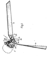
- This fuse is provided with an arming device substantially comprising a striker member 3 movable axially in the direction of its longitudinal axis, and a detonator 4, carried by a slide 5 movable from a first position (shown in Figure 1) in which the detonator is located out of the path of the striker member 3, to a second position in which the detonator is brought into the path of the member and beneath a conical tip 6 with which the member itself is provided.
- the striker member 3 and the detonator 4 are movable in suitable seats formed in a body 7 of the fuse and the first substantially comprises a stem provided with a threaded section 9 normally screwed into a corresponding threaded hole of a small bush 10 axially movable within the body 7 but prevented from rotating with respect thereto; this striker member is movable from a first position (shown in Figure 1) in which the conical tip 6 is inserted into a corresponding conical seat of the slide 5 to prevent the displacement of this latter, to a second position in which it allows the displacement of the slide itself;
- the striker member 3 can comprise, as in the embodiment of Figure 1, a cylindrical section 12 the diameter of which is less than the internal diameter of the threading formed in the bush 10, as well as an annular projection 15; therefore the first defined second position of the striker member 3 can be reached when the threaded section 9 is completely unscrewed from the corresponding threaded hole of the bush 10 and the cylindrical section 12 of the member itself is located within the hole in this
- the slide 5 can pass from the first to the second position defined above by the action of a spring 16, and is stopped in the said position by the action of a shoulder 17 pre-arranged to abut against a corresponding tab 18 of the body 7.
- the striker member 3 is provided with a pair of strip form flexible elements 19, one end of which is fixed to the striker member itself and each of which can be disposed, when the sub-munition is expelled from the projectile, in a manner which will be described, in the configuration schematically shown in Figure 1 in which each of the said sections forms a twisted element having a substantially rectilinear axis.
- Each'flexible element 19 is provided in correspondence with the zone of connection with the striker member 3, with a reinforcing plate 20 ( Figure 1) conveniently made of metal sheet, the edge 21 of which facing the free end of the element itself is substantially rectilinear and forms an angle other than 90° with the longitudinal axis of the flexible element for the purpose of making this assume a predetermined twist.
- each plate 20 has tongues folded onto the flexible element 19 and is fixed to this in any convenient manner, for example by means of riveting.
- the ends of the flexible elements 19 which are fixed to the striker member 3 are disposed between a pair of washers 22 and 23 ( Figure 3) which are coupled to an end pin 24 of the member itself, which is plastically deformed in such a way as to form a head 25 to clamp the washers and the flexible elements against a corresponding shoulder of the striker member 3.
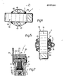
- the washer 23 is provided, as is clearly seen in Figure 6, with a plurality of notches 27 which can be filled with the material of the pin 24 when this is plastically deformed; the washer itself is then provided with a pair of radial teeth 28 each of which projects-upwardly with respect to the washer itself and is able to cooperate with a corresponding edge of one of the plates 20.
- Holes 29 are formed in the slide 5 and in the body 7, which holes have substantially coincident axes when the slide itself is located in the first, previously defined position and are able to receive a pin 34, the purpose of which is to prevent the diplacement of the slide 5 and therefore to constitute a safety pin for the arming system; the same purpose is performed by a cotter pin 35 which is inserted into a transverse slot 36 of the body 7 in such a way as to lock the axial displacement of the bush 10 and therefore of the striker member 3.
- the pin 34 substantially comprises two substantially parallel sections 37 and 38, the first of which is inserted into the holes 29 whilst the second is located substantially on one side of the slide 5 for the purpose of allowing the assembly of the two flexible elements 19, suitable folded, to be disposed above the slide itself in such a way as to form a pack 39.
- Figure 7 differs from that shown in Figure 3 by the fact that the stem of the striker member 3 is completely threaded as far as the annular projection 15.
- This second embodiment allows means to be formed, in a manner which will be explained, for the purpose of preventing rotation of the striker member when this has been brought into the first-defined second position.
- the assembly of the fuse onto the associated sub-munition can be effected in the following manner.
- the pack 39 of flexible elements 19 is positioned with respect to the body 7 of the fuse as illustrated in Figures 2 and 4, in which that is to say, the longitudinal axis of the pack itself is substantially parallel to that of the slide 5.
- This configuration can be obtained by making the striker member 3 to which the pack itself is rigidly connected rotate with respect to the associated bush 10; in this position the pin 34 does not interfere with the pack 39, the section 38 of the pin itself being disposed on one side of the slide 5 and therefore to one side of the pack itself as is clearly seen in Figure 3.
- the two tongues 40 ( Figure 4) of the body 7 are completely uncovered and accessible, these being provided with holes 41 in which can be inserted corresponding screws to fix the fuse to the sub-munition 2.
- the pack 39 can be turned substantially through 45° in such a way as to align the longitudinal axis of the pack itself substantially with that of the slide 5 as is clearly seen in Figure 5; in the said configuration, by acting on the end sections of the pack itself, this can be put into a less bulky configuration such as that necessary to be able to fit the sub-munition itself into the interior of the associated housing provided in the projectile which will have to transport the sub-munition itself.
- a fuse constructed according to the embodiment of Figures from 1 to 3 can be used if the sub-munition is to be expelled from a projectile which is not provided with rotary movement and therefore one which is constituted, for example, by the head of a rocket. If, on the other hand, this projectile is provided with rotary movement, that is if it is constituted, for example, by a projectile shot from the mouth of a conventional gun, the fuse of the embodiment of Figure 3 can be preferably utilised. In this case the rotation of the striker member 3 controlled by the flexible sections 19 is stopped when the annular projection 15 of the member itself comes to rest against the corresponding shoulder of the bush 10.
- connection made in the manner described, between the flexible elements 19 and the striker member 3 is very reliable; in fact, the washer 23 is torsionally locked with respect to the pin 24 because of the material of the pin itself which is introduced into the slots 27 of the washer; on the other hand, if the locking of the ends of the flexible elements 19 formed by means of the two washers 22 and 23 were not sufficient for the transmission of the moment from the flexible elements to the striker member, and therefore relative rotation took place between these members, as soon as the edges of the small plate 20 of the flexible elements 19 came into contact with the corresponding teeth 28 of the washer 23, these latter would be able to draw the flexible elements into rotation.
Landscapes
- Engineering & Computer Science (AREA)
- General Engineering & Computer Science (AREA)
- Physics & Mathematics (AREA)
- Fluid Mechanics (AREA)
- Holding Or Fastening Of Disk On Rotational Shaft (AREA)
- Vending Machines For Individual Products (AREA)
- Aiming, Guidance, Guns With A Light Source, Armor, Camouflage, And Targets (AREA)
- Lock And Its Accessories (AREA)
- Fuses (AREA)
- Air Bags (AREA)
Applications Claiming Priority (2)
| Application Number | Priority Date | Filing Date | Title |
|---|---|---|---|
| IT6759285 | 1985-06-28 | ||
| IT67592/85A IT1183905B (it) | 1985-06-28 | 1985-06-28 | Spoletta per submunizione atta ad essere espulsa da un vettore |
Publications (1)
| Publication Number | Publication Date |
|---|---|
| EP0207281A1 true EP0207281A1 (fr) | 1987-01-07 |
Family
ID=11303695
Family Applications (1)
| Application Number | Title | Priority Date | Filing Date |
|---|---|---|---|
| EP86107061A Withdrawn EP0207281A1 (fr) | 1985-06-28 | 1986-05-23 | Fusée pour sous-projectiles lancés à partir d'une roquette |
Country Status (9)
| Country | Link |
|---|---|
| US (1) | US4726292A (fr) |
| EP (1) | EP0207281A1 (fr) |
| KR (1) | KR870000571A (fr) |
| DK (1) | DK288986A (fr) |
| ES (1) | ES8800424A1 (fr) |
| GR (1) | GR861685B (fr) |
| IT (1) | IT1183905B (fr) |
| NO (1) | NO862582L (fr) |
| PT (1) | PT82863A (fr) |
Cited By (2)
| Publication number | Priority date | Publication date | Assignee | Title |
|---|---|---|---|---|
| EP0681157A3 (fr) * | 1994-05-06 | 1996-07-24 | Simmel Difesa Spa | Allumeur pour une sous-munition muni d'un dispositif d'autodestruction sans retard. |
| FR2801099A1 (fr) * | 1999-11-17 | 2001-05-18 | Giat Ind Sa | Systeme d'amorcage de la charge explosive d'une sous- munition |
Families Citing this family (7)
| Publication number | Priority date | Publication date | Assignee | Title |
|---|---|---|---|---|
| IL82066A (en) * | 1987-03-31 | 1992-03-29 | Israel State | Fuse for sub-munition warhead |
| DE3925235A1 (de) * | 1989-07-29 | 1991-01-31 | Rheinmetall Gmbh | Bombletzuender |
| US5067410A (en) * | 1990-12-21 | 1991-11-26 | The United States Of America As Represented By The Secretary Of The Army | Flexible wing |
| SE504857C2 (sv) * | 1995-04-27 | 1997-05-12 | Bofors Ab | Sätt vid substridsdel samt substridsdel |
| US6308632B1 (en) * | 1998-11-23 | 2001-10-30 | James E. Shaffer | Deployable folded propeller assembly for aerial projectiles |
| US6874425B1 (en) * | 2001-05-18 | 2005-04-05 | Day & Zimmermann, Inc. | Projectile carrying sub-munitions |
| US6564716B1 (en) * | 2001-12-05 | 2003-05-20 | Kdi Precision Products, Inc. | Fuzes having centrifugal arming lock for a munition |
Citations (7)
| Publication number | Priority date | Publication date | Assignee | Title |
|---|---|---|---|---|
| GB123014A (en) * | 1918-08-31 | 1919-02-13 | Edward Fredrick Haynes | Improvements relating to Aerial-fuse Bombs. |
| FR800738A (fr) * | 1936-01-15 | 1936-07-17 | Parachute à voilure tournante | |
| US2614636A (en) * | 1947-04-12 | 1952-10-21 | Richard H Prewitt | Rotor parachute |
| US2742859A (en) * | 1946-12-20 | 1956-04-24 | Charles F Bowersett | Nose fuze for a bomb |
| FR1163575A (fr) * | 1955-12-31 | 1958-09-29 | Gotex Ab | Parachute |
| US4488488A (en) * | 1982-12-23 | 1984-12-18 | The United States Of America As Represented By The Secretary Of The Army | Warhead safety and ribbon chute holder |
| US4492166A (en) * | 1977-04-28 | 1985-01-08 | Martin Marietta Corporation | Submunition having terminal trajectory correction |
Family Cites Families (9)
| Publication number | Priority date | Publication date | Assignee | Title |
|---|---|---|---|---|
| US1690331A (en) * | 1924-08-11 | 1928-11-06 | Secretary Of War Of The United | Supersensitive fuse for drop bombs |
| US1751616A (en) * | 1925-03-02 | 1930-03-25 | Secretary Of War Of The United | Combination fuse |
| US2076602A (en) * | 1936-06-24 | 1937-04-13 | Harold G Towner | Fuse for projectiles |
| US2131037A (en) * | 1937-10-11 | 1938-09-27 | Harold M Brayton | Bomb nose fuse |
| US3273834A (en) * | 1961-04-04 | 1966-09-20 | Bernal L Bower | Air drop autorotating gyroplane drop chutes |
| US3712217A (en) * | 1970-06-02 | 1973-01-23 | Us Army | Dispenser launched air arming bomb fuze |
| US3913483A (en) * | 1972-08-11 | 1975-10-21 | Us Army | Grenade with fuze |
| US3964391A (en) * | 1973-09-04 | 1976-06-22 | The United States Of America As Represented By The Secretary Of The Army | Dispenser-launched munition with two-stage spin-imparting vanes |
| US3998164A (en) * | 1975-12-15 | 1976-12-21 | The United States Of America As Represented By The Secretary Of The Army | Self-destruct delay fuze |
-
1985
- 1985-06-28 IT IT67592/85A patent/IT1183905B/it active
-
1986
- 1986-05-23 EP EP86107061A patent/EP0207281A1/fr not_active Withdrawn
- 1986-05-29 US US06/867,936 patent/US4726292A/en not_active Expired - Fee Related
- 1986-06-18 ES ES556211A patent/ES8800424A1/es not_active Expired
- 1986-06-19 DK DK288986A patent/DK288986A/da not_active Application Discontinuation
- 1986-06-26 NO NO862582A patent/NO862582L/no unknown
- 1986-06-27 GR GR861685A patent/GR861685B/el unknown
- 1986-06-27 PT PT82863A patent/PT82863A/pt not_active Application Discontinuation
- 1986-06-28 KR KR1019860005225A patent/KR870000571A/ko not_active Withdrawn
Patent Citations (7)
| Publication number | Priority date | Publication date | Assignee | Title |
|---|---|---|---|---|
| GB123014A (en) * | 1918-08-31 | 1919-02-13 | Edward Fredrick Haynes | Improvements relating to Aerial-fuse Bombs. |
| FR800738A (fr) * | 1936-01-15 | 1936-07-17 | Parachute à voilure tournante | |
| US2742859A (en) * | 1946-12-20 | 1956-04-24 | Charles F Bowersett | Nose fuze for a bomb |
| US2614636A (en) * | 1947-04-12 | 1952-10-21 | Richard H Prewitt | Rotor parachute |
| FR1163575A (fr) * | 1955-12-31 | 1958-09-29 | Gotex Ab | Parachute |
| US4492166A (en) * | 1977-04-28 | 1985-01-08 | Martin Marietta Corporation | Submunition having terminal trajectory correction |
| US4488488A (en) * | 1982-12-23 | 1984-12-18 | The United States Of America As Represented By The Secretary Of The Army | Warhead safety and ribbon chute holder |
Cited By (2)
| Publication number | Priority date | Publication date | Assignee | Title |
|---|---|---|---|---|
| EP0681157A3 (fr) * | 1994-05-06 | 1996-07-24 | Simmel Difesa Spa | Allumeur pour une sous-munition muni d'un dispositif d'autodestruction sans retard. |
| FR2801099A1 (fr) * | 1999-11-17 | 2001-05-18 | Giat Ind Sa | Systeme d'amorcage de la charge explosive d'une sous- munition |
Also Published As
| Publication number | Publication date |
|---|---|
| IT1183905B (it) | 1987-10-22 |
| IT8567592A0 (it) | 1985-06-28 |
| PT82863A (en) | 1986-07-01 |
| ES556211A0 (es) | 1987-11-01 |
| KR870000571A (ko) | 1987-02-19 |
| DK288986A (da) | 1986-12-29 |
| NO862582L (no) | 1986-12-29 |
| GR861685B (en) | 1986-09-10 |
| US4726292A (en) | 1988-02-23 |
| DK288986D0 (da) | 1986-06-19 |
| ES8800424A1 (es) | 1987-11-01 |
| NO862582D0 (no) | 1986-06-26 |
Similar Documents
| Publication | Publication Date | Title |
|---|---|---|
| US4653401A (en) | Self destructing fuse for sub-munitions to be expelled from a rocket | |
| DE3883821T2 (de) | Sicherung für eine Submunition. | |
| DE3337987C2 (de) | Flugkörper für den Angriff von Zielobjekten, insbesondere gepanzerten Objekten beim Überfliegen | |
| CA1310042C (fr) | Interrupteur inertiel a impulsions multiples | |
| US5243912A (en) | Arming delay, dual environment safe, fuze | |
| US4726292A (en) | Fuse for sub-munitions to be expelled from a rocket | |
| EP0068534B1 (fr) | Dispositif de sécurité pour la fusée d'un projectile stabilisé par rotation | |
| US3995557A (en) | Base fuze for a spinning projectile | |
| WO2000046567A1 (fr) | Fusee percutante a destruction automatique | |
| US3425353A (en) | Arming and safety mechanism for a drag chute retarded bomb | |
| DE3610358C2 (fr) | ||
| US7258068B2 (en) | Safety and arming apparatus and method for a munition | |
| US2817295A (en) | Firing pin for rocket fuze | |
| US3808972A (en) | Dual function bomb | |
| US6035783A (en) | High performance fuze | |
| US6530324B1 (en) | Fuze mechanism for a munition | |
| EP0104138B1 (fr) | Dispositif pour armer et neutraliser une fusée électrique pour munition | |
| US6564716B1 (en) | Fuzes having centrifugal arming lock for a munition | |
| US4667600A (en) | Safe/arm explosive transfer mechanism | |
| US3901156A (en) | Safety and arming device for fuses | |
| EP0218947B1 (fr) | Fusée d'impact comportant une amorce à percussion | |
| US6848367B2 (en) | Priming device for the explosive charge of a sub-munition | |
| US3146714A (en) | Delay fuze for rotating munition | |
| US2976804A (en) | Separation means | |
| US2594340A (en) | Centrifugally armed fuse |
Legal Events
| Date | Code | Title | Description |
|---|---|---|---|
| PUAI | Public reference made under article 153(3) epc to a published international application that has entered the european phase |
Free format text: ORIGINAL CODE: 0009012 |
|
| AK | Designated contracting states |
Kind code of ref document: A1 Designated state(s): AT BE CH DE FR GB LI NL SE |
|
| STAA | Information on the status of an ep patent application or granted ep patent |
Free format text: STATUS: THE APPLICATION IS DEEMED TO BE WITHDRAWN |
|
| 18D | Application deemed to be withdrawn |
Effective date: 19870708 |
|
| RIN1 | Information on inventor provided before grant (corrected) |
Inventor name: GATTI, ANTONIO |