EP0207293A2 - Procédé et dispositif pour le séchage de produits sensibles à la chaleur ayant une humidité initiale élevée - Google Patents
Procédé et dispositif pour le séchage de produits sensibles à la chaleur ayant une humidité initiale élevée Download PDFInfo
- Publication number
- EP0207293A2 EP0207293A2 EP86107307A EP86107307A EP0207293A2 EP 0207293 A2 EP0207293 A2 EP 0207293A2 EP 86107307 A EP86107307 A EP 86107307A EP 86107307 A EP86107307 A EP 86107307A EP 0207293 A2 EP0207293 A2 EP 0207293A2
- Authority
- EP
- European Patent Office
- Prior art keywords
- dryer
- drying
- products
- dried
- flight
- Prior art date
- Legal status (The legal status is an assumption and is not a legal conclusion. Google has not performed a legal analysis and makes no representation as to the accuracy of the status listed.)
- Granted
Links
- 238000000034 method Methods 0.000 title claims abstract description 35
- 238000001035 drying Methods 0.000 title claims abstract description 28
- 230000008569 process Effects 0.000 title claims abstract description 23
- 239000012530 fluid Substances 0.000 claims abstract description 25
- 239000005018 casein Substances 0.000 claims abstract description 6
- BECPQYXYKAMYBN-UHFFFAOYSA-N casein, tech. Chemical compound NCCCCC(C(O)=O)N=C(O)C(CC(O)=O)N=C(O)C(CCC(O)=N)N=C(O)C(CC(C)C)N=C(O)C(CCC(O)=O)N=C(O)C(CC(O)=O)N=C(O)C(CCC(O)=O)N=C(O)C(C(C)O)N=C(O)C(CCC(O)=N)N=C(O)C(CCC(O)=N)N=C(O)C(CCC(O)=N)N=C(O)C(CCC(O)=O)N=C(O)C(CCC(O)=O)N=C(O)C(COP(O)(O)=O)N=C(O)C(CCC(O)=N)N=C(O)C(N)CC1=CC=CC=C1 BECPQYXYKAMYBN-UHFFFAOYSA-N 0.000 claims abstract description 6
- 235000021240 caseins Nutrition 0.000 claims abstract description 6
- GUBGYTABKSRVRQ-XLOQQCSPSA-N Alpha-Lactose Chemical compound O[C@@H]1[C@@H](O)[C@@H](O)[C@@H](CO)O[C@H]1O[C@@H]1[C@@H](CO)O[C@H](O)[C@H](O)[C@H]1O GUBGYTABKSRVRQ-XLOQQCSPSA-N 0.000 claims abstract description 4
- GUBGYTABKSRVRQ-QKKXKWKRSA-N Lactose Natural products OC[C@H]1O[C@@H](O[C@H]2[C@H](O)[C@@H](O)C(O)O[C@@H]2CO)[C@H](O)[C@@H](O)[C@H]1O GUBGYTABKSRVRQ-QKKXKWKRSA-N 0.000 claims abstract description 4
- 239000008101 lactose Substances 0.000 claims abstract description 4
- 235000018102 proteins Nutrition 0.000 claims abstract description 4
- 102000004169 proteins and genes Human genes 0.000 claims abstract description 4
- 108090000623 proteins and genes Proteins 0.000 claims abstract description 4
- 238000011144 upstream manufacturing Methods 0.000 claims description 2
- 238000013021 overheating Methods 0.000 abstract description 5
- 238000005243 fluidization Methods 0.000 abstract 1
- 239000000047 product Substances 0.000 description 26
- 238000004140 cleaning Methods 0.000 description 3
- 230000008901 benefit Effects 0.000 description 2
- 239000002245 particle Substances 0.000 description 2
- 230000000630 rising effect Effects 0.000 description 2
- 235000013162 Cocos nucifera Nutrition 0.000 description 1
- 244000060011 Cocos nucifera Species 0.000 description 1
- 241000196324 Embryophyta Species 0.000 description 1
- 238000009825 accumulation Methods 0.000 description 1
- 230000001580 bacterial effect Effects 0.000 description 1
- 230000015572 biosynthetic process Effects 0.000 description 1
- 230000008859 change Effects 0.000 description 1
- 239000007795 chemical reaction product Substances 0.000 description 1
- 230000001143 conditioned effect Effects 0.000 description 1
- 238000010276 construction Methods 0.000 description 1
- 238000001816 cooling Methods 0.000 description 1
- 238000002845 discoloration Methods 0.000 description 1
- 235000013305 food Nutrition 0.000 description 1
- 230000007774 longterm Effects 0.000 description 1
- 239000000463 material Substances 0.000 description 1
- 238000005259 measurement Methods 0.000 description 1
- 235000013372 meat Nutrition 0.000 description 1
- JTJMJGYZQZDUJJ-UHFFFAOYSA-N phencyclidine Chemical class C1CCCCN1C1(C=2C=CC=CC=2)CCCCC1 JTJMJGYZQZDUJJ-UHFFFAOYSA-N 0.000 description 1
- 229920003023 plastic Polymers 0.000 description 1
- 239000004033 plastic Substances 0.000 description 1
- 230000008092 positive effect Effects 0.000 description 1
- 230000009467 reduction Effects 0.000 description 1
- 230000007704 transition Effects 0.000 description 1
Images
Classifications
-
- F—MECHANICAL ENGINEERING; LIGHTING; HEATING; WEAPONS; BLASTING
- F26—DRYING
- F26B—DRYING SOLID MATERIALS OR OBJECTS BY REMOVING LIQUID THEREFROM
- F26B17/00—Machines or apparatus for drying materials in loose, plastic, or fluidised form, e.g. granules, staple fibres, with progressive movement
- F26B17/10—Machines or apparatus for drying materials in loose, plastic, or fluidised form, e.g. granules, staple fibres, with progressive movement with movement performed by fluid currents, e.g. issuing from a nozzle, e.g. pneumatic, flash, vortex or entrainment dryers
-
- F—MECHANICAL ENGINEERING; LIGHTING; HEATING; WEAPONS; BLASTING
- F26—DRYING
- F26B—DRYING SOLID MATERIALS OR OBJECTS BY REMOVING LIQUID THEREFROM
- F26B3/00—Drying solid materials or objects by processes involving the application of heat
- F26B3/02—Drying solid materials or objects by processes involving the application of heat by convection, i.e. heat being conveyed from a heat source to the materials or objects to be dried by a gas or vapour, e.g. air
- F26B3/06—Drying solid materials or objects by processes involving the application of heat by convection, i.e. heat being conveyed from a heat source to the materials or objects to be dried by a gas or vapour, e.g. air the gas or vapour flowing through the materials or objects to be dried
- F26B3/08—Drying solid materials or objects by processes involving the application of heat by convection, i.e. heat being conveyed from a heat source to the materials or objects to be dried by a gas or vapour, e.g. air the gas or vapour flowing through the materials or objects to be dried so as to loosen them, e.g. to form a fluidised bed
-
- F—MECHANICAL ENGINEERING; LIGHTING; HEATING; WEAPONS; BLASTING
- F26—DRYING
- F26B—DRYING SOLID MATERIALS OR OBJECTS BY REMOVING LIQUID THEREFROM
- F26B3/00—Drying solid materials or objects by processes involving the application of heat
- F26B3/02—Drying solid materials or objects by processes involving the application of heat by convection, i.e. heat being conveyed from a heat source to the materials or objects to be dried by a gas or vapour, e.g. air
- F26B3/10—Drying solid materials or objects by processes involving the application of heat by convection, i.e. heat being conveyed from a heat source to the materials or objects to be dried by a gas or vapour, e.g. air the gas or vapour carrying the materials or objects to be dried with it
Definitions
- the invention relates to a method for drying heat-sensitive products which can be fluidized in the dried state and have a high initial moisture, e.g. Casein, lactose, proteins and the like, in a fluidized bed process.
- a high initial moisture e.g. Casein, lactose, proteins and the like
- the process is one-step, the dryer is a so-called long-term dryer, in which relatively small amounts of air are used in order to fluidize the product to be dried, but not entrained in the air flow, and relatively low air temperatures are set in order to prevent the coarse grain from becoming higher Moisture dries unevenly, is locally overheated and thereby baked, baked on or undergoes another quality reduction.
- Pendulum rakes or other additional movement devices serve the same purpose in the entrance area of the fluid bed dryer which is referred to as the wet or accumulation zone. Nevertheless, the formation of deposits on the walls cannot be avoided. Since they represent bacterial sources, laborious and lengthy internal wet cleaning is required at least once a day.
- the invention has for its object to provide a drying method of the type mentioned and a device suitable for its implementation, with the help of which the products to be dried faster than before, but still more evenly and with better security against partial overheating with their often harmful consequences can be.
- the above object is achieved in that the products are predried in a first stage using the fly-bed method and then finish-dried in a second stage using the fluidized bed method.
- Flight layer dryers which are also referred to as flight dryers or turbo flyer dryers, are short-term dryers. They atomize the product to be dried in a hot air stream that sweeps the particles away and dries them in seconds. Because of the high air temperature, the flight layer process for drying heat-sensitive products has not been considered. The practically unavoidable fluctuations in the initial moisture content, depending on the setting of the drying conditions, must necessarily lead to partial overheating or insufficient drying.
- the surprisingly positive effect of the invention is due to the fact that the flight layer process is used according to the invention only for predrying.
- the parameters are set so that the product to be dried after predrying is on the one hand dry enough to be able to fluidize evenly fine-grained at the feed point in the subsequent fluidized bed process (avoidance of the wet zone and its problems), and on the other hand the residual moisture is sufficient after the predrying to safely avoid heat damage in this first stage of the process.
- the fluidized bed process can be larger due to the fine-grained pre-dried product Enforce air volume because it distributes itself evenly and reaches all particles, so that it also dries faster and, moreover, takes full advantage of its advantageous properties of gentle drying and precise control, since locally different coincidences are excluded during the transition from coarse grain high moisture to evenly fluidizable fine grain.
- the invention offers the possibility of controlling the drying conditions in the case of finished drying in a fluidized bed process as a function of the moisture after predrying in the fly bed process, as a result of which the residual moisture can be kept constant with very good accuracy.
- the new device for carrying out the method according to the invention thus consists of a fluid bed dryer which is known per se and which is preceded by a flight bed dryer which is also known per se.
- a flight bed dryer which is also known per se.
- two flight layer dryers are arranged in parallel, which can alternately be connected upstream of the fluid bed dryer. In this way, the drying process does not need to be interrupted when cleaning one of the flight layer dryers.
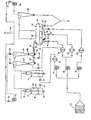
- the system shown consists essentially of a fluid bed dryer 10 and two parallel flight layer dryers (turbo flight dryers) 12 and 14.
- the latter is the product to be dried, eg. B. casein coming from a decanter, alternately via a mincer (mincer) 16 and an inlet tube 18.
- Only one turbo flight dryer 12 or 14 need be in operation at a time.
- the double arrangement allows continuous operation even during the day After cleaning one of the two dryers 12 or 14.
- the fluid bed dryer 10 and the flight layer dryer 12 and 14 have a common supply air supply.
- the supply air is drawn in and conditioned by an intake air filter 20.
- a first blower 22 presses the supply air via a heater 24 either into one of the two flight layer dryers 12 or 14.
- the switching between these takes place by means of two air flaps 26 and 28 with a pneumatic actuator, one of the air flaps being open and the other being closed.
- the fluid bed dryer 10 is supplied separately with supply air in three separate zones.
- a second blower 30 presses heated supply air via a heater 32 into the inlet zone denoted by 34 and via a heater 36 further heated supply air into the central zone 38 of the fluid bed dryer 10.
- a third fan 40 conveys cooled supply air via a cooler 42 to the outlet zone 44 of the fluid bed dryer .
- a cyclone 46 and 48 is assigned to the two flight layer dryers 12 and 14 in a known manner.
- the product pre-dried in one of the flight dryer 12 or 14 arrives with its exhaust air in the associated cyclone 46 or 48 and is separated there, while the exhaust air is extracted via an air flap 50 or 52 with an actuator by an exhaust air blower 54 and via a further air flap 56 is promoted with an actuator to an outlet indicated at 58.
- the exhaust air from the fluid bed dryer 10 is drawn off by a further exhaust air blower 60 via a cyclone 62 and conveyed to the outlet 58 (exhaust air filter not shown) via an air flap 64 with an actuator.
- the supply air is distributed to the individual zones 34, 38, 44 of the fluid bed dryer 10 by means of air flaps 66, 68, 70 with actuator.
- Two further air flaps 72 and 74 control the supply of feed air branched off behind the heater 32 to vibrating conveyor troughs 76 and 78, which connect the outlet of the cyclones 46 and 48 to the product inlet opening 80 of the fluid bed dryer 10. It goes without saying that only one cyclone 46 or 48 and a single vibrating conveyor trough 76 or 78 are present in systems with only a single flight layer dryer.
- the drying conditions in the turbo flight dryer 12 and 14 are set so that the product then still has a moisture content of about 25 to 40%.
- An initial moisture of 70% is e.g. B. reduced to a residual moisture of 30%. Because of this relatively high residual moisture in the finely divided state, the product takes on despite the usually high air temperature in the turbo Flight dryer no harm. However, it then maintains its fine-grained consistency and, in this immediately fluidizable state, reaches the inlet zone 34 of the fluidized bed dryer 10 via the product inlet opening 80.
- the two-stage construction of the system with a turbo flight dryer for predrying and a fluidized bed dryer for finished drying offers the possibility between these two stages by means of an infrared moisture meter 96, which is preferably arranged at the outlet of the cyclone 46 or 48 behind the turbo flight dryer 12 or 14 is to constantly measure the moisture still present and to control the operating parameters, in particular the air quantity and temperature, of the turbo flight dryer 12 or 14 as a function of this measurement result.
- the conditions in the fluidized bed dryer 10 can be controlled by sensors attached to it and, if necessary, also influenced by the infrared meter 96.
- the fluid bed dryer only one or more than the three zones shown with each have different air supply and temperature.
- the fluid bed dryer can be designed to be stationary or in a known manner as a vibration fluid bed dryer. It preferably has a round cross section and a pull-out and exchangeable inflow floor to adapt to different products.
- the method described takes place under negative pressure.
- the negative pressure contributes to the fact that the damp material is sucked into the dryer.
- a particular advantage of the new process is that existing single-stage drying systems with fluid bed dryers can be converted to two-stage operation at relatively low cost, since the existing two-stage operation can also be carried out with the existing fluid bed dryer.
Landscapes
- Engineering & Computer Science (AREA)
- Mechanical Engineering (AREA)
- General Engineering & Computer Science (AREA)
- Life Sciences & Earth Sciences (AREA)
- Microbiology (AREA)
- Drying Of Solid Materials (AREA)
Priority Applications (1)
| Application Number | Priority Date | Filing Date | Title |
|---|---|---|---|
| AT86107307T ATE59900T1 (de) | 1985-06-01 | 1986-05-29 | Verfahren und vorrichtung zum trocknen von waermeempfindlichen produkten mit hoher anfangsfeuchte. |
Applications Claiming Priority (2)
| Application Number | Priority Date | Filing Date | Title |
|---|---|---|---|
| DE3519750 | 1985-06-01 | ||
| DE19853519750 DE3519750A1 (de) | 1985-06-01 | 1985-06-01 | Verfahren und vorrichtung zum trocknen von waermeempfindlichen produkten mit hoher anfangsfeuchte |
Publications (3)
| Publication Number | Publication Date |
|---|---|
| EP0207293A2 true EP0207293A2 (fr) | 1987-01-07 |
| EP0207293A3 EP0207293A3 (en) | 1988-05-11 |
| EP0207293B1 EP0207293B1 (fr) | 1991-01-09 |
Family
ID=6272242
Family Applications (1)
| Application Number | Title | Priority Date | Filing Date |
|---|---|---|---|
| EP86107307A Expired - Lifetime EP0207293B1 (fr) | 1985-06-01 | 1986-05-29 | Procédé et dispositif pour le séchage de produits sensibles à la chaleur ayant une humidité initiale élevée |
Country Status (3)
| Country | Link |
|---|---|
| EP (1) | EP0207293B1 (fr) |
| AT (1) | ATE59900T1 (fr) |
| DE (2) | DE3519750A1 (fr) |
Families Citing this family (2)
| Publication number | Priority date | Publication date | Assignee | Title |
|---|---|---|---|---|
| DE102014004815A1 (de) | 2013-04-03 | 2014-10-09 | Glatt Ingenieurtechnik Gmbh | Rotationstrocknerstern und Verfahren zur Behandlung von Feststoffpartikeln |
| DE102013005921A1 (de) | 2013-04-03 | 2014-10-09 | Glatt Ingenieurtechnik Gmbh | Fluidisierungsapparat |
Family Cites Families (6)
| Publication number | Priority date | Publication date | Assignee | Title |
|---|---|---|---|---|
| AT220075B (de) * | 1957-06-14 | 1962-03-12 | Hermann Orth | Wirbel- und Flugschicht-Trockner |
| DE1729279C3 (de) * | 1967-03-13 | 1975-05-28 | Buettner-Schilde-Haas Ag, 4150 Krefeld | Der Vortrocknung dienende Vorrichtung für Wirbelbett-Trockner |
| DD102799A1 (fr) * | 1972-07-19 | 1973-12-20 | ||
| DE2427932B2 (de) * | 1974-06-10 | 1978-02-09 | Bergwerksverband GmbH; Didier Engineering GmbH; 4300 Essen | Flugstromtrockner mit eine diffusorartige engstelle aufweisendem trocknungsrohr |
| DE2544048A1 (de) * | 1975-10-02 | 1977-04-21 | Kloeckner Humboldt Deutz Ag | Verfahren und einrichtung zur thermischen behandlung von nicht rieselfaehigen, klebrigen, klumpigen, temperaturempfindlichen materialien |
| DE3246461A1 (de) * | 1982-12-15 | 1984-06-20 | H. Orth GmbH, 6737 Böhl-Iggelheim | Vorrichtung zur behandlung fluidisierbarer feststoffe im fliessbettverfahren |
-
1985
- 1985-06-01 DE DE19853519750 patent/DE3519750A1/de active Granted
-
1986
- 1986-05-29 AT AT86107307T patent/ATE59900T1/de not_active IP Right Cessation
- 1986-05-29 EP EP86107307A patent/EP0207293B1/fr not_active Expired - Lifetime
- 1986-05-29 DE DE8686107307T patent/DE3676749D1/de not_active Expired - Lifetime
Also Published As
| Publication number | Publication date |
|---|---|
| EP0207293B1 (fr) | 1991-01-09 |
| ATE59900T1 (de) | 1991-01-15 |
| DE3676749D1 (de) | 1991-02-14 |
| EP0207293A3 (en) | 1988-05-11 |
| DE3519750A1 (de) | 1986-12-04 |
| DE3519750C2 (fr) | 1988-06-16 |
Similar Documents
| Publication | Publication Date | Title |
|---|---|---|
| DE3131471C2 (fr) | ||
| DE2103671C2 (de) | Verfahren und Anlage zum Konditionieren von Tabak | |
| DE2638446A1 (de) | Tabaktrockner | |
| DE1532070A1 (de) | Tabakdurchlauftrockener mit Heissluftbeheizung | |
| DE2904308A1 (de) | Verfahren und anordnung zum trocknen von tabak | |
| DE2340490A1 (de) | Verfahren zum steuern der feuchte von tabak und steuerungsanordnung eines trockners fuer tabak | |
| DE1532063A1 (de) | Verfahren und Anlage zum Verballen von Gruenballen | |
| DE3114712C2 (fr) | ||
| DE2747232A1 (de) | Verfahren und vorrichtung zur durchfuehrung von behandlungsvorgaengen fuer schuettgueter u.dgl. | |
| DE2019369A1 (de) | Verfahren zum Trocknen von Tabak und Trocknungsfoerderer | |
| DE1299237C2 (de) | Verfahren und vorrichtung zum trocknen von tabak | |
| WO2007104389A1 (fr) | Dispositif de séchage du tabac | |
| DE102009007789B3 (de) | Trocknungsanlage für landwirtschaftliche Körnerfrüchte | |
| EP0207293B1 (fr) | Procédé et dispositif pour le séchage de produits sensibles à la chaleur ayant une humidité initiale élevée | |
| DE2404608A1 (de) | Verfahren und vorrichtung zur regulierung der temperatur und des feuchtigkeitsgehaltes von stoffteilchen | |
| DE1779393B1 (de) | Vakuumtrocknungskammer zur kontinuierlichen Gefriertrocknung von grobstueckig anfallendem,im Endzustand kleinteiligem Gut | |
| EP0058892B1 (fr) | Procédé et dispositif pour le séchage de céréales avec de l'air chaud | |
| DE1206771B (de) | Verfahren und Vorrichtung zum Trocknen von Tabak oder aehnlichem Gut | |
| DE102020004278A1 (de) | Vorrichtung zur Trocknung landwirtschaftlicher Produkte | |
| EP0499902B1 (fr) | Dispositif de refroidissement pour particules granulaires cristallines ayant tendance à coller | |
| DE949219C (de) | Verfahren und Vorrichtung zum pneumatischen Stufentrocknen | |
| DE3711098C2 (fr) | ||
| DD206204A1 (de) | Verfahren und einrichtung zum trocknen von rieselfaehigem gut | |
| DE2243670A1 (de) | Verfahren und einrichtung zum kontinuierlichen trocknen von koernigen stoffen in einer wirbelschicht | |
| DE2132226A1 (de) | Verfahren und vorrichtung zum konditionieren von tabak |
Legal Events
| Date | Code | Title | Description |
|---|---|---|---|
| PUAI | Public reference made under article 153(3) epc to a published international application that has entered the european phase |
Free format text: ORIGINAL CODE: 0009012 |
|
| AK | Designated contracting states |
Kind code of ref document: A2 Designated state(s): AT BE CH DE FR GB IT LI NL SE |
|
| RAP1 | Party data changed (applicant data changed or rights of an application transferred) |
Owner name: H. ORTH GMBH |
|
| PUAL | Search report despatched |
Free format text: ORIGINAL CODE: 0009013 |
|
| AK | Designated contracting states |
Kind code of ref document: A3 Designated state(s): AT BE CH DE FR GB IT LI NL SE |
|
| RAP1 | Party data changed (applicant data changed or rights of an application transferred) |
Owner name: HERMANN WALDNER GMBH & CO. |
|
| 17P | Request for examination filed |
Effective date: 19880610 |
|
| 17Q | First examination report despatched |
Effective date: 19890519 |
|
| GRAA | (expected) grant |
Free format text: ORIGINAL CODE: 0009210 |
|
| AK | Designated contracting states |
Kind code of ref document: B1 Designated state(s): AT BE CH DE FR GB IT LI NL SE |
|
| PG25 | Lapsed in a contracting state [announced via postgrant information from national office to epo] |
Ref country code: IT Free format text: LAPSE BECAUSE OF FAILURE TO SUBMIT A TRANSLATION OF THE DESCRIPTION OR TO PAY THE FEE WITHIN THE PRE;WARNING: LAPSES OF ITALIAN PATENTS WITH EFFECTIVE DATE BEFORE 2007 MAY HAVE OCCURRED AT ANY TIME BEFORE 2007. THE CORRECT EFFECTIVE DATE MAY BE DIFFERENT FROM THE ONE RECORDED.SCRIBED TIME-LIMIT Effective date: 19910109 Ref country code: BE Effective date: 19910109 Ref country code: FR Effective date: 19910109 Ref country code: SE Effective date: 19910109 Ref country code: NL Effective date: 19910109 Ref country code: GB Effective date: 19910109 |
|
| REF | Corresponds to: |
Ref document number: 59900 Country of ref document: AT Date of ref document: 19910115 Kind code of ref document: T |
|
| REF | Corresponds to: |
Ref document number: 3676749 Country of ref document: DE Date of ref document: 19910214 |
|
| PG25 | Lapsed in a contracting state [announced via postgrant information from national office to epo] |
Ref country code: AT Effective date: 19910529 |
|
| EN | Fr: translation not filed | ||
| PG25 | Lapsed in a contracting state [announced via postgrant information from national office to epo] |
Ref country code: CH Effective date: 19910531 Ref country code: LI Effective date: 19910531 |
|
| NLV1 | Nl: lapsed or annulled due to failure to fulfill the requirements of art. 29p and 29m of the patents act | ||
| GBV | Gb: ep patent (uk) treated as always having been void in accordance with gb section 77(7)/1977 [no translation filed] | ||
| PLBE | No opposition filed within time limit |
Free format text: ORIGINAL CODE: 0009261 |
|
| STAA | Information on the status of an ep patent application or granted ep patent |
Free format text: STATUS: NO OPPOSITION FILED WITHIN TIME LIMIT |
|
| 26N | No opposition filed | ||
| REG | Reference to a national code |
Ref country code: CH Ref legal event code: PL |
|
| PGFP | Annual fee paid to national office [announced via postgrant information from national office to epo] |
Ref country code: DE Payment date: 19980723 Year of fee payment: 13 |
|
| PG25 | Lapsed in a contracting state [announced via postgrant information from national office to epo] |
Ref country code: DE Free format text: LAPSE BECAUSE OF NON-PAYMENT OF DUE FEES Effective date: 20000301 |