EP0207352B1 - Sondenkontrollverfahren und -gerät für einen Apparat mit mehreren Freiheitsgraden - Google Patents
Sondenkontrollverfahren und -gerät für einen Apparat mit mehreren Freiheitsgraden Download PDFInfo
- Publication number
- EP0207352B1 EP0207352B1 EP86108198A EP86108198A EP0207352B1 EP 0207352 B1 EP0207352 B1 EP 0207352B1 EP 86108198 A EP86108198 A EP 86108198A EP 86108198 A EP86108198 A EP 86108198A EP 0207352 B1 EP0207352 B1 EP 0207352B1
- Authority
- EP
- European Patent Office
- Prior art keywords
- movement
- optical
- output
- actuators
- gradient
- Prior art date
- Legal status (The legal status is an assumption and is not a legal conclusion. Google has not performed a legal analysis and makes no representation as to the accuracy of the status listed.)
- Expired
Links
- 230000007246 mechanism Effects 0.000 title claims description 33
- 238000000034 method Methods 0.000 title claims description 24
- 230000003287 optical effect Effects 0.000 claims description 45
- 239000013307 optical fiber Substances 0.000 claims description 21
- 230000008859 change Effects 0.000 claims description 17
- 230000004044 response Effects 0.000 claims description 5
- 239000000835 fiber Substances 0.000 claims description 4
- 230000001747 exhibiting effect Effects 0.000 claims 1
- 238000006073 displacement reaction Methods 0.000 description 5
- 238000010276 construction Methods 0.000 description 3
- 238000005259 measurement Methods 0.000 description 3
- 238000013459 approach Methods 0.000 description 2
- 230000003247 decreasing effect Effects 0.000 description 2
- 238000002474 experimental method Methods 0.000 description 2
- 230000008569 process Effects 0.000 description 2
- 238000012935 Averaging Methods 0.000 description 1
- 230000008878 coupling Effects 0.000 description 1
- 238000010168 coupling process Methods 0.000 description 1
- 238000005859 coupling reaction Methods 0.000 description 1
- 238000013461 design Methods 0.000 description 1
- 238000010586 diagram Methods 0.000 description 1
- 238000011156 evaluation Methods 0.000 description 1
- 238000003754 machining Methods 0.000 description 1
- 238000010606 normalization Methods 0.000 description 1
- 230000009467 reduction Effects 0.000 description 1
- 239000000523 sample Substances 0.000 description 1
- 239000004065 semiconductor Substances 0.000 description 1
- 238000004904 shortening Methods 0.000 description 1
- VLCQZHSMCYCDJL-UHFFFAOYSA-N tribenuron methyl Chemical compound COC(=O)C1=CC=CC=C1S(=O)(=O)NC(=O)N(C)C1=NC(C)=NC(OC)=N1 VLCQZHSMCYCDJL-UHFFFAOYSA-N 0.000 description 1
- 239000013598 vector Substances 0.000 description 1
Images



Classifications
-
- B—PERFORMING OPERATIONS; TRANSPORTING
- B23—MACHINE TOOLS; METAL-WORKING NOT OTHERWISE PROVIDED FOR
- B23Q—DETAILS, COMPONENTS, OR ACCESSORIES FOR MACHINE TOOLS, e.g. ARRANGEMENTS FOR COPYING OR CONTROLLING; MACHINE TOOLS IN GENERAL CHARACTERISED BY THE CONSTRUCTION OF PARTICULAR DETAILS OR COMPONENTS; COMBINATIONS OR ASSOCIATIONS OF METAL-WORKING MACHINES, NOT DIRECTED TO A PARTICULAR RESULT
- B23Q1/00—Members which are comprised in the general build-up of a form of machine, particularly relatively large fixed members
- B23Q1/25—Movable or adjustable work or tool supports
- B23Q1/26—Movable or adjustable work or tool supports characterised by constructional features relating to the co-operation of relatively movable members; Means for preventing relative movement of such members
- B23Q1/34—Relative movement obtained by use of deformable elements, e.g. piezoelectric, magnetostrictive, elastic or thermally-dilatable elements
- B23Q1/36—Springs
-
- B—PERFORMING OPERATIONS; TRANSPORTING
- B23—MACHINE TOOLS; METAL-WORKING NOT OTHERWISE PROVIDED FOR
- B23Q—DETAILS, COMPONENTS, OR ACCESSORIES FOR MACHINE TOOLS, e.g. ARRANGEMENTS FOR COPYING OR CONTROLLING; MACHINE TOOLS IN GENERAL CHARACTERISED BY THE CONSTRUCTION OF PARTICULAR DETAILS OR COMPONENTS; COMBINATIONS OR ASSOCIATIONS OF METAL-WORKING MACHINES, NOT DIRECTED TO A PARTICULAR RESULT
- B23Q15/00—Automatic control or regulation of feed movement, cutting velocity or position of tool or work
- B23Q15/20—Automatic control or regulation of feed movement, cutting velocity or position of tool or work before or after the tool acts upon the workpiece
- B23Q15/22—Control or regulation of position of tool or workpiece
- B23Q15/24—Control or regulation of position of tool or workpiece of linear position
-
- G—PHYSICS
- G02—OPTICS
- G02B—OPTICAL ELEMENTS, SYSTEMS OR APPARATUS
- G02B6/00—Light guides; Structural details of arrangements comprising light guides and other optical elements, e.g. couplings
- G02B6/24—Coupling light guides
- G02B6/36—Mechanical coupling means
- G02B6/38—Mechanical coupling means having fibre to fibre mating means
- G02B6/3801—Permanent connections, i.e. wherein fibres are kept aligned by mechanical means
- G02B6/3803—Adjustment or alignment devices for alignment prior to splicing
-
- G—PHYSICS
- G02—OPTICS
- G02B—OPTICAL ELEMENTS, SYSTEMS OR APPARATUS
- G02B6/00—Light guides; Structural details of arrangements comprising light guides and other optical elements, e.g. couplings
- G02B6/24—Coupling light guides
- G02B6/42—Coupling light guides with opto-electronic elements
- G02B6/4201—Packages, e.g. shape, construction, internal or external details
- G02B6/4219—Mechanical fixtures for holding or positioning the elements relative to each other in the couplings; Alignment methods for the elements, e.g. measuring or observing methods especially used therefor
- G02B6/422—Active alignment, i.e. moving the elements in response to the detected degree of coupling or position of the elements
- G02B6/4226—Positioning means for moving the elements into alignment, e.g. alignment screws, deformation of the mount
-
- G—PHYSICS
- G02—OPTICS
- G02B—OPTICAL ELEMENTS, SYSTEMS OR APPARATUS
- G02B6/00—Light guides; Structural details of arrangements comprising light guides and other optical elements, e.g. couplings
- G02B6/24—Coupling light guides
- G02B6/42—Coupling light guides with opto-electronic elements
- G02B6/4201—Packages, e.g. shape, construction, internal or external details
- G02B6/4219—Mechanical fixtures for holding or positioning the elements relative to each other in the couplings; Alignment methods for the elements, e.g. measuring or observing methods especially used therefor
- G02B6/422—Active alignment, i.e. moving the elements in response to the detected degree of coupling or position of the elements
- G02B6/4227—Active alignment methods, e.g. procedures and algorithms
Definitions
- the present invention relates to a probing method and a probing control apparatus for a mechanism with multiple degree of freedom which is used in automation of adjusting operation. More particularly, the invention is concerned with a probing method and a probing control apparatus of the kind referred to in the preamble portions of patent claims 1 and 2, respectively.
- the optical axis alignment is attained by moving the optical fiber unaxially, i.e., with one-degree of freedom, and fixing the optical fiber at a point where the output from the fiber is maximized.
- the movement of optical fiber in one-degree of freedom it is not possible to attain the true maximum output point due to, for example, lack of precision of parts, with a result that the optical axis alignment cannot be conducted with sufficiently high precision.
- CA-A-1 066 426 discloses a probing method for effecting optical access alignment of an optical fiber in a light-emitting device with optical fiber, said method employing a mechanism with a plurality of degrees of freedom of movement. A plurality of actuators for driving said mechanism are driven, a change in the optical output from the object in response to the driving of lack of the actuators is determined and it is determined whether conditions of said optical output have occured exceeding a predetermined value. Further, this document shows a probing control apparatus comprising adjusting means having a plurality of degrees of freedom of movement for adjusting deflection of an optical axis of an optical element, means for detecting an optical output of said optical element, and control means for controlling said adjusting means so as to increase the said output of said optical element.
- an object of the invention is to provide a probing control method and apparatus with a mechanism with multiple degree of freedom so as to move an object such as an optical fiber three-dimensionally, thereby to find out the point where the level of the output from the object is maximized.
- a method of driving in one-by-one fashion and in accordance with a predetermined sequence, n pieces of actuators for actuating a mechanism with n-degrees of freedom, the method comprising detecting the amount of change in the output from a control object in response to the operation of said actuators, forming a command for each actuator from driving data containing the amount of movement of said actuator in the preceding operation and the amount of change in the output from the control object, and driving each actuator in accordance with the thus formed driving data.
- Fig. 1 shows an example of the construction of a laser diode.
- a reference numeral 1 d notes a laser diode chip fixed to a sub-mount 2 which is in turn is secured to a frame 3.
- an optical fiber 4 passes through a hole formed in the central portion of a supporting post 5 which is fixed at its one end to a frame 3. The output end is led to the outside through a hole formed in the frame 3.
- the position of the light-emitting portion of the laser diode chip 1 fluctuates with respect to the frame 3, due to insufficient precision of machining of the chip and insufficient precision of mounting on the sub-mount.
- the position of the end of the optical fiber fluctuates.
- it is necessary that the optical axes of the laser diode chip 1 and the optical fiber 4 are aligned with a precision in the order of 0.1 ⁇ m to 1 ⁇ m.
- the alignment has been attained by grasping one end of the supporting post 5, moving the supporting post 5 in the X and Y directions or X, Y and ⁇ directions, thereby moving the end of the optical fiber 4 while plastically deforming the supporting post 5.
- the output from the optical fiber 4 is observed to probe the position where the output value exceeds a predetermined level, thereby attaining optical axis alignment between the optical fiber 4 and the laser diode chip 1.
- Fig. 3 shows a mechanism having three degrees of freedom, as an example of the mechanism with multiple degree of freedom.
- This mechanism 6 has a fine adjustment device composed of an outer frame 7, intermediate frame 8, inner frame 9 and an end frame 10.
- the outer frame 7 and the inner frame 8 are coupled to each other through a parallel leaf spring mechanism.
- the inner frame 8 and the intermediate frame 9 are coupled to each other through a similar parallel leaf spring mechanism.
- the outer frame 7 and the inner frame 8, and the inner frame 8 and the inner frame 9 are adapted to be displaced in X and Y directions by piezoelectric actuators 11 and 12, in proportion to the voltage applied to the piezoelectric actuators.
- the inner frame 9 and the end frame 10 are coupled through a spring mechanism which is constructed in such a manner as to cross at the central points, and are adapted to be actuated by a piezoelectric actuator 13, thereby effecting minute angular movement about the central point (in the ⁇ direction) proportional to the voltage applied to the piezoelectric actuator.
- a supporting post gripper is fixed to the lower side (not shown) of the end frame 10. The gripper can grip the supporting post 5 so as to deflect the latter in three directions, i.e., X, Y and ⁇ directions.
- the outer frame 7 is fixed to the stationary member.
- Fig. 4 shows the arrangement of the whole portion of the invention.
- the output from the laser diode 1 is detected by a detector 14 and is sent to a controller 15.
- the controller 15 computes the amounts of driving of three piezoelectric actuators in accordance with the following method, and applies to each piezoelectric actuator a voltage corresponding to the computed value.
- the position of the gripper when it has just gripped the supporting post 5 is expressed by x0, y0 and ⁇ 0, while the output of the laser diode in this state is represented by f0.
- the factors x, y and ⁇ have initial values x0, y0 and ⁇ 0, the amounts of initial displacement ⁇ x1, ⁇ y1 and ⁇ 1 are determined.
- Symbols ⁇ x, ⁇ y and ⁇ represent the displacements in x, y and ⁇ directions, while suffix n represents the n-th cycles of movement.
- the optical output f detected by the detector 14 through the fiber is determined by x, y and ⁇ .
- a movement by amount ⁇ x1 is caused and the gradient of the optical power distribution surface is determined by the difference in the optical output between the state before the movement and the state after the movement.
- f0 and f x1 represent the value of the optical output in the states before and after the movement by the amount ⁇ x1.
- a movement by the amount ⁇ y1 is effected to provide the following condition.
- f x1 and f y1 represent the optical output values obtained in the states before and after the movement by the amount ⁇ y1 and can be determined by measurement.
- a movement by the amount ⁇ 1 is conducted so that the following condition is obtained.
- the amounts ⁇ x2, ⁇ y2 and ⁇ 2 of the second cycle of operation in the x, y and ⁇ directions are determined as follows.
- A, B, j and k are constants the optimum values of which are obtainable through experiments. If the constant A is positive, the movement is caused in such a direction as to reduce s, whereas, when the constant A is negative, the movement is caused in such a direction as to decrease the value s. It is to be noted also that the amount of movement is decreased as the value h is increased.
- the cycles of movement are further repeated until the number n exceed a predetermiend value or the value s comes down below a predetermined value or the value h exceeds a predetermined value.
- the movement in respective steps for the purpose of the probing is intended not only for the approach to the designated maximum value but also for the measurement of the gradient in the vicinity of the maximum value point.
- an efficient probing is executed because the probing and the measurement of gradient are conducted at one time.
- the movement by the amount ⁇ x in the x-axis direction is followed by the movement in the - ⁇ x direction, and a subsequent movement ⁇ y in the y-axis direction is followed by a movement - ⁇ y , and finally a movement is effected in the steepest direction on the x, y plane.
- the method of the invention is superior to the above-explained severest method in that (1) the number of the moving cycles is smaller, and that (2) number of sharp turns (movement - ⁇ x following the movement ⁇ x means 180° change in the moving direction) is smaller.
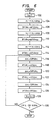
- Step 104 a movement ⁇ x10 is caused in the direction x1.
- the amount of change in the optical output is expressed by ⁇ f.
- the gradient of the optical power distribution surface shown by the far field pattern in the direction x1 is expressed as ⁇ f/ ⁇ x10 (Step 106).
- Step 108 a movement ⁇ x20 is effected in the direction x2 from the instant point.
- the value of inclination calculated immediately after the previous movement in the direction x1 ( ⁇ f/ ⁇ x1, ⁇ f/ ⁇ x10 for the first movement) is used as ⁇ f/ ⁇ x10.
- the amount of change in the optical output in this state is expressed by ⁇ f and the inclination during this movement is given as ⁇ f/ ⁇ x1 (Step 118).
- a movement ⁇ x2 is effected in the direction x2, followed by consecutive movements ⁇ x3, ⁇ x4, ...., ⁇ x n , with calculation of the inclinations 120-128.
- the probing is continued in the manner described and is ceased when a predetermined value f c is reached or when a predetermined number of probing cycles is reached.
- the gradient e m varies largely depending on the value of the estimation function, such that it takes large value in the region where the estimation function has a large value and a small value in the region where the estimation function takes a small value.
- the gradient e m is largely varied by the absolute value.
- the amount of change in the value of the estimation function is normalized as follows by the value f m-1 of the estimation function as obtained before the movement.
- the amounts ⁇ x1, ⁇ X2, ...., ⁇ x n of movement effected by the fine motion mechanism are determined in such a manner as to make the estimation function to approach the maximum value from the instant position, i.e., in the direction of e m *.
- a and p are constants (A>0, p ⁇ 0).
- the fine motion mechanism progressively moves towards the direction of the gradient so that the estimation function value reaches the maximum value.
- the gradient becomes zero when the maximum value is reached. In this state, the mechanism does not work any more, so that the aligning operation is finished.
- the amount of movement to be achieved by the fine motion mechanism is determined on the basis of the gradient which in turn is obtained by normalizing the amount of change in the evaluation function.
- the mechanism is driven in accordance with the rate of change of the estimation function value rather than the absolute value of the estimation function.
- the large amount of movement given by the fine motion mechanism is large when the mechanism is remote from the position corresponding to the maximum value but is small when the position corresponding to the maximum value has been approached, whereby an efficient probing is obtained.
- the displacements of the mechanism when it has just gripped the supporting post 5 by the gripper are given by X0, y0 and ⁇ 0, while the optical output in this state is represented by f0.
- the X-direction actuator is driven (Step 202) in the X direction by amount corresponding to the amount ⁇ X1 which is set beforehand, and the optical output in this state is measured to obtain the following condition (Step 204).
- e m ⁇ *-1, ..., e m ⁇ *-l represent, respectively, the gradients in the cycles which are 1 to l th preceding cycles as counted from the instant position, and are given by the formula (21).
- Symbols ⁇ 0 to ⁇ l represent the weight coefficients.
- the terms ⁇ fm*X, ⁇ fm * Y and ⁇ fm* ⁇ in the right side of this formula should be replaced, in a strict sense, with the values which are obtained by normalizing the amount of change in the optical outputs obtained when the fine motion mechanism is driven simultaneously in all directions X, Y and ⁇ by amounts ⁇ X m , ⁇ Y m and ⁇ m .
- the normalized values can be regarded as being materially the same as the values ⁇ f m * X, ⁇ fm*Y and ⁇ fm * ⁇ , so that the condition of formula (28) is valid.
- the amount ⁇ Xm in the X direction is determined in accordance with formula (20) on the basis of the formula (23).
- the fine motion mechanism is mvoed in the X direction by amount ⁇ Xm (Step 220) and the (3m + 2) th optical output fmY is measured.
- the gradient E my* also is determiend (Step 224) as follows. where, ⁇ X m+1 equals to ⁇ Xm.
- Step 226 the amount ⁇ Ym of movement in the Y direction is determined (Step 226) by the following formulae.
- Step 2228 the fine motion mechanism is actuated (Step 228) by amount ⁇ Y m in the Y direction and the optical output fm ⁇ for (3m + 3) th cycle is measured.
- the gradient E m * ⁇ and the amount ⁇ m of movement in the ⁇ direction are determined in accordance with the following formulae.
- ⁇ m+1 is set as ⁇ m and 1 is added to m so that the process returns to the initial state and then repeated.
- This repetitional operation is continued and is stopped when the optical output f has been increased to exceed a predetermined value F (Steps 222, 230, 238), or when the gradient is decreased to reduce the value down below a predetermined value E (Step 242) or when the number m of the probing cycles has been increased to exceed a predetermined number M (Step 204), whereby the optical axis alignment is accomplished.
- the estimation function calculated from these signals can have the maximum value.
- the determination of the gradient of the estimation function value is conducted in each step during the probing, so that it becomes unnecessary to determine the gradients in all directions, thus providing advantages such as higher efficiency of probing, shortening of the probing time, and reduction in the load on the mechanism.
- the gradient of the estimation function is estimated without being affected by the absolute value of the estimation function, the requirement for a change in the parameter can be reduced even for devices which involve fluctuation of the output.
- the gradient is determined taking into account also the gradients in the past, it is possible to absorb any abrupt apparent change in the gradient due to noise, so that the probing can be conducted smoothly even though the control is conducted in accordance with differentiated values.
Landscapes
- Physics & Mathematics (AREA)
- Engineering & Computer Science (AREA)
- Mechanical Engineering (AREA)
- General Physics & Mathematics (AREA)
- Optics & Photonics (AREA)
- Optical Couplings Of Light Guides (AREA)
- Testing Of Optical Devices Or Fibers (AREA)
Claims (2)
- Ein Prüfverfahren zum Ausführen der Ausrichtung der optischen Achse einer Lichtleitfaser in einem eine Lichtleitfaser enthaltenden lichtemittierenden Element mit einem Bezugsobjekt, welches ein Mittel zur Erfassung der optischen Ausgabe der Lichtleitfaser besitzt, wobei das Verfahren einen auf die Faser wirkenden Mechanismus mit einer Mehrzahl von Bewegungs-Freiheitsgraden verwendet, wobei eine Mehrzahl von Betätigungselementen zum Antreiben des Mechanismus angetrieben werden, eine Änderung der optischen Ausgabe aufgrund des Antreibens eines jeden der Betätigungselemente bestimmt wird und festgestellt wird, ob ein Zustand aufgetreten ist, in dem die optische Ausgabe einen vorgegebenen Wert übersteigt,
dadurch gekennzeichnet, daß
der Mechanismus wenigstens drei Bewegungs-Freiheitsgrade besitzt,
die Mehrzahl der Betätigungselemente um vorgegebene Beträge einzeln angetrieben werden, wobei auf der Grundlage der bestimmten Änderung ein Gradient der optischen Ausgabe des Bezugsobjektes erhalten wird;
der Betrag der Bewegung zum Antreiben eines jeden der Betätigungselemente auf der Grundlage des Gradienten in der optischen Ausgabe in einem unmittelbar vorhergehenden Schritt des Antreibens desselben Betätigungselementes erhalten wird, wobei dasselbe Betätigungselement um den auf diese Weise erhaltenen Bewegungsbetrag angetrieben wird und die optische Ausgabe aufgrund des Antreibens eines jeden Betätigungselementes nacheinander gemessen wird, und
bestimmt wird, ob ein Zustand aufgetreten ist, in dem die optische Ausgabe einen ersten vorgegebenen Wert übersteigt oder in dem der Gradient in der optischen Ausgabe unter einen zweiten vorgegebenen Wert fällt, wobei der Antrieb der Betätigungselemente angehalten wird, wenn einer der Zustände aufgetreten ist, und der Schritt des einzelnen Antreibens der Betätigungselemente wiederholt wird, wenn keiner der Zustände aufgetreten ist. - Eine Prüf-Steuervorrichtung, mit einem eine Mehrzahl von Bewegungs-Freiheitsgraden aufweisenden Einstellmittel (6) zum Einstellen der Ablenkung einer optischen Achse einer Lichtleitfaser (4) in bezug auf ein Bezugsobjekt (1), wobei das Objekt (1) ein Mittel (14) zur Erfassung einer optischen Ausgabe der Lichtleitfaser besitzt, und einem Steuermittel (15) zum Steuern des Einstellmittels, derart, daß die Ausgabe der Lichtleitfaser erhöht wird,
dadurch gekennzeichnet, daß- das Einstellmittel eine Mehrzahl von Rahmen (7, 8, 9, 10) besitzt, die einen einen Mittelpunkt darstellenden Rahmen (10) und eine Mehrzahl von die Rahmen verbindenden Mechanismen enthalten, um wenigstens drei Bewegungs-Freiheitsgrade des Einstellmittels um den Mittelpunkt zu schaffen, wobei der eine Rahmen mit der die Ausgabe bewirkenden Lichtleitfaser in Verbindung ist;- eine Mehrzahl von Betätigungselementen (11, 12, 13) angeordnet sind, um aufgrund von Befehlen, die die Beträge der Bewegung der Rahmen durch das jeweilige der Betätigungselemente festlegen, die Rahmen relativ zu den Koordinatenachsen (X, Y, ϑ) eines Koordinatensystems während Einstelloperations-Zyklen zu verschieben; und- das Steuermittel die Änderung in der Ausgabe für jeden Einstelloperations-Zyklus bestimmt, den Wert des Gradienten in der Ausgabe für jeden Zyklus auf der Grundlage der bestimmten Änderung bestimmt, die Befehle berechnet, damit sich die optische Ausgabe einem einen ersten vorgegebenen Wert übersteigenden Wert annähert oder damit sich der Gradient einem einen zweiten vorgegebenen Wert unterschreitenden Wert annähert, und die Betätigungselemente auf der Grundlage der Befehle antreibt.
Applications Claiming Priority (4)
| Application Number | Priority Date | Filing Date | Title |
|---|---|---|---|
| JP129806/85 | 1985-06-17 | ||
| JP60129806A JPH0652488B2 (ja) | 1985-06-17 | 1985-06-17 | 光ファイバの光軸探索方法 |
| JP215014/85 | 1985-09-30 | ||
| JP21501485A JPS6275508A (ja) | 1985-09-30 | 1985-09-30 | 自動光軸合せ装置の極値探索方式 |
Publications (3)
| Publication Number | Publication Date |
|---|---|
| EP0207352A2 EP0207352A2 (de) | 1987-01-07 |
| EP0207352A3 EP0207352A3 (en) | 1987-03-18 |
| EP0207352B1 true EP0207352B1 (de) | 1991-12-11 |
Family
ID=26465086
Family Applications (1)
| Application Number | Title | Priority Date | Filing Date |
|---|---|---|---|
| EP86108198A Expired EP0207352B1 (de) | 1985-06-17 | 1986-06-16 | Sondenkontrollverfahren und -gerät für einen Apparat mit mehreren Freiheitsgraden |
Country Status (3)
| Country | Link |
|---|---|
| US (1) | US4884015A (de) |
| EP (1) | EP0207352B1 (de) |
| DE (1) | DE3682834D1 (de) |
Families Citing this family (18)
| Publication number | Priority date | Publication date | Assignee | Title |
|---|---|---|---|---|
| US4984885A (en) * | 1989-12-15 | 1991-01-15 | General Electric Company | Method and apparatus for high power optical fiber injection and alignment |
| DE4009380A1 (de) * | 1990-03-23 | 1991-09-26 | Standard Elektrik Lorenz Ag | Lasermodul |
| US5061039A (en) * | 1990-06-22 | 1991-10-29 | The United States Of America As Represented By The United States Department Of Energy | Dual axis translation apparatus and system for translating an optical beam and related method |
| SE467474B (sv) * | 1990-09-17 | 1992-07-20 | Radians Innova Ab | Positioneringsanordning |
| FR2691825A1 (fr) * | 1992-05-26 | 1993-12-03 | Bernay Automation | Appareil didactique de démonstration des degrés de liberté d'un assemblage mécanique. |
| US5535297A (en) * | 1993-12-16 | 1996-07-09 | Honeywell Inc. | Micro-alignment method |
| US5623337A (en) * | 1994-09-28 | 1997-04-22 | Nec Corporation | Method capable of quickly adjusting an optical axis of an optical fiber |
| US6074103A (en) * | 1996-10-15 | 2000-06-13 | Sdl, Inc. | Aligning an optical fiber with electroluminescent semiconductor diodes and other optical components |
| US5870517A (en) * | 1997-10-07 | 1999-02-09 | Integrated Device Technology, Inc. | Package including self-aligned laser diode and method of aligning a laser diode |
| US6253010B1 (en) * | 1998-04-17 | 2001-06-26 | Iolon, Inc. | System and method for efficient coupling between optical elements |
| US6498892B1 (en) | 2000-08-03 | 2002-12-24 | Murray R. Harman | Positioning device especially for assembling optical components |
| JP3833889B2 (ja) * | 2000-11-29 | 2006-10-18 | 古河電気工業株式会社 | レーザダイオード素子と光ファイバの調心方法およびその方法を用いた調心装置およびレーザダイオードモジュール |
| TW552444B (en) * | 2001-02-16 | 2003-09-11 | Siemens Dematic Electronics As | Method for connecting a first end of an optical fiber to a laser module, system for connecting a first end of an optical fiber to a first optical module, system for connecting a first end of an optical fiber to a laser transmitter |
| US6470023B1 (en) * | 2001-03-05 | 2002-10-22 | Terabeam Corporation | Optical fiber position controller for multiple degrees of freedom |
| US7114860B2 (en) * | 2002-12-17 | 2006-10-03 | Photintech, Inc. | Method and device for coupling a light emitting source to an optical waveguide |
| CN104016117B (zh) * | 2014-05-28 | 2017-01-18 | 京东方科技集团股份有限公司 | 一种自动调整基板位置的叉板及调整方法 |
| US10746945B1 (en) * | 2017-10-09 | 2020-08-18 | Waymo Llc | Systems and methods for laser diode alignment |
| US11042004B1 (en) * | 2017-10-23 | 2021-06-22 | Waymo Llc | System and method for alignment of optical beams |
Family Cites Families (9)
| Publication number | Priority date | Publication date | Assignee | Title |
|---|---|---|---|---|
| JPS5537098B1 (de) * | 1971-07-15 | 1980-09-25 | ||
| CA1066426A (en) * | 1976-11-29 | 1979-11-13 | Frederick D. King | Method and apparatus for alignment of optical fibres with optoelectronic devices |
| US4191916A (en) * | 1977-11-23 | 1980-03-04 | Fujitsu Limited | Table positioning system including optical reference position measuring transducer |
| EP0036026B1 (de) * | 1980-03-10 | 1986-11-12 | Eaton-Optimetrix Inc. | Adressierbare Positioniervorrichtung |
| CA1198797A (en) * | 1980-03-27 | 1985-12-31 | Optimetrix Corporation | X-y addressable workpiece positioner having an improved x-y address indicia sensor |
| US4500165A (en) * | 1982-04-02 | 1985-02-19 | Codenoll Technology Corporation | Method and apparatus for aligning optical fibers |
| JPH0619280B2 (ja) * | 1983-09-24 | 1994-03-16 | 名古屋大学長 | 光学式自動位置決め装置 |
| US4514674A (en) * | 1983-12-22 | 1985-04-30 | International Business Machines Corporation | Electromagnetic X-Y-Theta precision positioner |
| EP0155528B1 (de) * | 1984-02-22 | 1989-02-01 | Siemens Aktiengesellschaft | Optoelektronisches Modulgehäuse |
-
1986
- 1986-06-16 EP EP86108198A patent/EP0207352B1/de not_active Expired
- 1986-06-16 DE DE8686108198T patent/DE3682834D1/de not_active Expired - Lifetime
- 1986-06-17 US US06/875,189 patent/US4884015A/en not_active Expired - Fee Related
Also Published As
| Publication number | Publication date |
|---|---|
| EP0207352A3 (en) | 1987-03-18 |
| EP0207352A2 (de) | 1987-01-07 |
| US4884015A (en) | 1989-11-28 |
| DE3682834D1 (de) | 1992-01-23 |
Similar Documents
| Publication | Publication Date | Title |
|---|---|---|
| EP0207352A2 (de) | Sondenkontrollverfahren und -gerät für einen Apparat mit mehreren Freiheitsgraden | |
| EP0464764B1 (de) | Antriebsvorrichtung | |
| Popa et al. | Micro and mesoscale robotic assembly | |
| Malis et al. | 2 1/2 D visual servoing | |
| Kang et al. | Analysis and design of parallel mechanisms with flexure joints | |
| Weiss et al. | Dynamic visual servo control of robots: an adaptive image-based approach | |
| US4451892A (en) | Method of and apparatus for measuring distances in numerically controlled machine tools | |
| Kieffer et al. | Robust and accurate time-optimal path-tracking control for robot manipulators | |
| Bai et al. | Fuzzy logic control to suppress noises and coupling effects in a laser tracking system | |
| US5463201A (en) | Seam-tracking apparatus for a welding system employing an array of eddy current elements | |
| Liu et al. | Design and characterization of four-degree-of-freedom fast steering mirror for laser compensation system | |
| US5442269A (en) | Robot control system | |
| US4702652A (en) | Advanced memory type profiling control method for a machine tool | |
| EP0508205B1 (de) | Hybrides Lage- und Kraftregelsystem | |
| Petrov et al. | Control of a robot-manipulator with obstacle avoidance under little information about the environment | |
| Bonen et al. | A novel electrooptical proximity sensor for robotics: Calibration and active sensing | |
| Lange et al. | Predictive vision based control of high speed industrial robot paths | |
| Luo et al. | A force/stiffness compensation method for precision multi-peg-hole assembly | |
| Arai et al. | Automated calibration for micro hand using visual information | |
| JPS62254004A (ja) | 多自由度機構の探索制御方式 | |
| Kurzweg et al. | Model-based optoelectronic packaging automation | |
| Petterson et al. | Force servocontrol of a commercial Gantry robot | |
| US4884014A (en) | Position control method | |
| JPS6275508A (ja) | 自動光軸合せ装置の極値探索方式 | |
| Zribi et al. | Variable structure control of two manipulators handling a constrained object |
Legal Events
| Date | Code | Title | Description |
|---|---|---|---|
| PUAI | Public reference made under article 153(3) epc to a published international application that has entered the european phase |
Free format text: ORIGINAL CODE: 0009012 |
|
| AK | Designated contracting states |
Kind code of ref document: A2 Designated state(s): DE FR GB |
|
| PUAL | Search report despatched |
Free format text: ORIGINAL CODE: 0009013 |
|
| AK | Designated contracting states |
Kind code of ref document: A3 Designated state(s): DE FR GB |
|
| 17P | Request for examination filed |
Effective date: 19870320 |
|
| 17Q | First examination report despatched |
Effective date: 19891025 |
|
| GRAA | (expected) grant |
Free format text: ORIGINAL CODE: 0009210 |
|
| AK | Designated contracting states |
Kind code of ref document: B1 Designated state(s): DE FR GB |
|
| REF | Corresponds to: |
Ref document number: 3682834 Country of ref document: DE Date of ref document: 19920123 |
|
| ET | Fr: translation filed | ||
| PLBE | No opposition filed within time limit |
Free format text: ORIGINAL CODE: 0009261 |
|
| STAA | Information on the status of an ep patent application or granted ep patent |
Free format text: STATUS: NO OPPOSITION FILED WITHIN TIME LIMIT |
|
| 26N | No opposition filed | ||
| PGFP | Annual fee paid to national office [announced via postgrant information from national office to epo] |
Ref country code: FR Payment date: 19940516 Year of fee payment: 9 |
|
| PGFP | Annual fee paid to national office [announced via postgrant information from national office to epo] |
Ref country code: GB Payment date: 19940606 Year of fee payment: 9 |
|
| PGFP | Annual fee paid to national office [announced via postgrant information from national office to epo] |
Ref country code: DE Payment date: 19940831 Year of fee payment: 9 |
|
| PG25 | Lapsed in a contracting state [announced via postgrant information from national office to epo] |
Ref country code: GB Effective date: 19950616 |
|
| GBPC | Gb: european patent ceased through non-payment of renewal fee |
Effective date: 19950616 |
|
| PG25 | Lapsed in a contracting state [announced via postgrant information from national office to epo] |
Ref country code: FR Effective date: 19960229 |
|
| PG25 | Lapsed in a contracting state [announced via postgrant information from national office to epo] |
Ref country code: DE Effective date: 19960301 |
|
| REG | Reference to a national code |
Ref country code: FR Ref legal event code: ST |