EP0207377A1 - Montage de mesure pour spectroscopie diélectrique - Google Patents
Montage de mesure pour spectroscopie diélectrique Download PDFInfo
- Publication number
- EP0207377A1 EP0207377A1 EP86108342A EP86108342A EP0207377A1 EP 0207377 A1 EP0207377 A1 EP 0207377A1 EP 86108342 A EP86108342 A EP 86108342A EP 86108342 A EP86108342 A EP 86108342A EP 0207377 A1 EP0207377 A1 EP 0207377A1
- Authority
- EP
- European Patent Office
- Prior art keywords
- temperature
- sample
- measurement
- measuring device
- measuring
- Prior art date
- Legal status (The legal status is an assumption and is not a legal conclusion. Google has not performed a legal analysis and makes no representation as to the accuracy of the status listed.)
- Withdrawn
Links
- 238000001566 impedance spectroscopy Methods 0.000 title 1
- 239000000463 material Substances 0.000 claims abstract description 19
- 238000000034 method Methods 0.000 claims abstract description 14
- 230000035699 permeability Effects 0.000 claims abstract description 7
- 238000005259 measurement Methods 0.000 claims description 23
- 238000012545 processing Methods 0.000 claims description 9
- 230000001105 regulatory effect Effects 0.000 claims description 7
- 230000032683 aging Effects 0.000 claims description 6
- 238000006243 chemical reaction Methods 0.000 claims description 4
- 238000004132 cross linking Methods 0.000 claims description 4
- 238000004519 manufacturing process Methods 0.000 claims description 4
- 238000012360 testing method Methods 0.000 claims description 4
- 239000004033 plastic Substances 0.000 claims description 2
- 229920003023 plastic Polymers 0.000 claims description 2
- 238000001816 cooling Methods 0.000 claims 1
- 230000007613 environmental effect Effects 0.000 claims 1
- 238000010438 heat treatment Methods 0.000 claims 1
- 239000000523 sample Substances 0.000 description 28
- RYGMFSIKBFXOCR-UHFFFAOYSA-N Copper Chemical compound [Cu] RYGMFSIKBFXOCR-UHFFFAOYSA-N 0.000 description 2
- 239000003990 capacitor Substances 0.000 description 2
- 239000011889 copper foil Substances 0.000 description 2
- 238000011161 development Methods 0.000 description 2
- 230000018109 developmental process Effects 0.000 description 2
- 238000010586 diagram Methods 0.000 description 2
- 238000003908 quality control method Methods 0.000 description 2
- 238000011160 research Methods 0.000 description 2
- 238000012369 In process control Methods 0.000 description 1
- 239000007795 chemical reaction product Substances 0.000 description 1
- 230000006378 damage Effects 0.000 description 1
- 238000013461 design Methods 0.000 description 1
- 230000000694 effects Effects 0.000 description 1
- 238000005516 engineering process Methods 0.000 description 1
- 238000011156 evaluation Methods 0.000 description 1
- 238000010965 in-process control Methods 0.000 description 1
- 238000011065 in-situ storage Methods 0.000 description 1
- 239000011261 inert gas Substances 0.000 description 1
- 239000007788 liquid Substances 0.000 description 1
- 230000006855 networking Effects 0.000 description 1
- 238000005457 optimization Methods 0.000 description 1
- 239000002985 plastic film Substances 0.000 description 1
- 229920006255 plastic film Polymers 0.000 description 1
- 238000002360 preparation method Methods 0.000 description 1
- 238000002203 pretreatment Methods 0.000 description 1
- 239000000047 product Substances 0.000 description 1
- 239000007787 solid Substances 0.000 description 1
- 239000000126 substance Substances 0.000 description 1
- 230000002123 temporal effect Effects 0.000 description 1
- 230000003685 thermal hair damage Effects 0.000 description 1
- 230000001052 transient effect Effects 0.000 description 1
Images


Classifications
-
- G—PHYSICS
- G01—MEASURING; TESTING
- G01N—INVESTIGATING OR ANALYSING MATERIALS BY DETERMINING THEIR CHEMICAL OR PHYSICAL PROPERTIES
- G01N33/00—Investigating or analysing materials by specific methods not covered by groups G01N1/00 - G01N31/00
- G01N33/44—Resins; Plastics; Rubber; Leather
- G01N33/442—Resins; Plastics
-
- G—PHYSICS
- G01—MEASURING; TESTING
- G01N—INVESTIGATING OR ANALYSING MATERIALS BY DETERMINING THEIR CHEMICAL OR PHYSICAL PROPERTIES
- G01N27/00—Investigating or analysing materials by the use of electric, electrochemical, or magnetic means
- G01N27/02—Investigating or analysing materials by the use of electric, electrochemical, or magnetic means by investigating impedance
- G01N27/22—Investigating or analysing materials by the use of electric, electrochemical, or magnetic means by investigating impedance by investigating capacitance
- G01N27/221—Investigating or analysing materials by the use of electric, electrochemical, or magnetic means by investigating impedance by investigating capacitance by investigating the dielectric properties
-
- G—PHYSICS
- G01—MEASURING; TESTING
- G01R—MEASURING ELECTRIC VARIABLES; MEASURING MAGNETIC VARIABLES
- G01R27/00—Arrangements for measuring resistance, reactance, impedance, or electric characteristics derived therefrom
- G01R27/02—Measuring real or complex resistance, reactance, impedance, or other two-pole characteristics derived therefrom, e.g. time constant
- G01R27/26—Measuring inductance or capacitance; Measuring quality factor, e.g. by using the resonance method; Measuring loss factor; Measuring dielectric constants ; Measuring impedance or related variables
- G01R27/2617—Measuring dielectric properties, e.g. constants
- G01R27/2623—Measuring-systems or electronic circuits
Definitions
- the invention relates to a measurement setup for determining electrical parameters such as dielectric constant, permeability number and loss factor of materials, in particular plastics.
- This measurement setup will be referred to below as a dielectric spectrometer.
- the property profile determined therefore serves to characterize materials for various applications, in particular for electronics. It is also essential for the incoming, processing and quality control of a product.
- the electrical property values have been recorded and calculated manually.
- the dielectric constant and the loss factor are usually only determined at room temperature and depending on the frequency. With one measuring point, however, no information about the material behavior under other temperature conditions can be found.
- test temperature is usually not recorded on the sample itself.
- the invention is based on the object of designing a measurement setup by means of which the characteristic values mentioned in the introduction are determined in small time units at predetermined parameters. Small time units are, for example, ⁇ 2 seconds.
- the dielectric spectrometer to be created is of great importance for the input, processing and quality control in research, development and production.
- the object underlying the invention is achieved in that for a structure according to the preamble, a thermal device with a controller and with sample holder, a measuring device for the electrical impedance and - derived therefrom - a control for the dielectric constant, the permeability number and the loss factor - And computing unit and an output unit, for example plotter, are provided.
- a thermal device with a controller and with sample holder, a measuring device for the electrical impedance and - derived therefrom - a control for the dielectric constant, the permeability number and the loss factor - And computing unit and an output unit, for example plotter.
- the dielectric spectrometer With the aid of the dielectric spectrometer according to the invention, it is possible to determine the aforementioned electrical characteristic values as a function of temperature, time and frequency within short time intervals. As a result, the measured values recorded are uniquely assigned to the selected parameters (such as temperature and / or frequency). It is very important to acquire the measured values in a matter of seconds in order to achieve the required high temporal resolution. The prerequisite for this is an optimal coordination of temperature control device, sample holder and measuring device as well as of control, regulating, computing and output units.
- a measuring setup according to the invention By means of different sample dimensions, correspondingly configured contacting within the sample holder and a suitable measuring device, it is possible with a measuring setup according to the invention to cover a frequency range from 0 Hz to 1 GHz.
- a clear material evaluation can only be carried out when temperature and frequency are taken into account at the same time.
- the respective aging behavior should be known for optimal material selection.
- aging conditions can be simulated and the measured electrical values can be used to infer the aging behavior.
- these reactions can be tracked in time based on the changes in the measured electrical values. This means that processing parameters can be adjusted accordingly and thus networking can be optimized.
- the dielectric spectrometer can also be used in process control.
- the production process is controlled in situ, that is, simultaneously with the process sequence, due to changes in the electrical properties of the material to be processed.
- Plastic films laminated with copper foil on both sides were used as samples.
- the copper foil serves as a contact electrode. As a result, any air gap that would distort the result is between the actual sample and prevents contacting.
- the samples were exposed to different temperature-time conditions before the measurement.
- the test object was electrically contacted by means of the sample holder and placed in the temperature chamber, which can, for example, heat up to 350 ° C and cool down to minus 150 ° C.
- the temperature control device is designed so that the interior can be flushed with inert gas during the measurement. If necessary, the measurement can also be carried out in a vacuum.
- the dimensions (area, thickness) of the test specimen were determined beforehand.
- the probe was inserted into the sample holder for temperature determination and control. Via the central computing, control and regulating unit, the desired type of measurement (in the example, determination of capacity and loss factor), the temperature profile and the measurement frequencies are specified by the user in a dialog process.
- the desired temperature cycle is run through and the necessary measurements are carried out in short time intervals by means of the measuring device.
- the associated temperature is thus recorded for each electrical measuring point. All data obtained in this way is shown on the output unit after appropriate preparation.
- the curve for a sample that was pretreated for half an hour at 200 ° C. is marked with a solid line.
- a dashed line shows a sample that was pretreated at 200 ° C for one hour.
- a dash-dotted line shows the course of the curve for a sample which was pretreated for one and a half hours at 200 ° C.
- a dotted curve applies to a sample that has been pretreated at 200 ° C for two hours.
- the upper curves are assigned to the dielectric constant ⁇ ⁇ and the lower curves to the loss factor D.
- the arrows in the figure give a corresponding indication.
- FIG. 2 shows the strong dependence of the dielectric constant and the loss factor of the sample on the frequency over the temperature.
- the curves of the sample which was pretreated for one hour at 200 ° C., are shown at the frequencies 1, 10 and 100 kHz.
- the solid line corresponds to the curve at 1 kHz, the dashed line to the curve at 10 kHz and the dash-dotted line to the curve at 100 kHz.
- the upper curves are assigned to the dielectric constant and the lower ones to the loss factor.
- the data obtained from both images lead to an optimization of the pretreatment and processing conditions and thus to an improved and consistent end product.
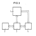
- FIG. 3 shows the functional diagram of the dielectric spectrometer. 1 with the temperature control device and sample holder is designated; 2 identifies the plotter, 3 the data processing system and 4 the measuring device.
- the sample holder consists of a plate capacitor for solid substances, but that for liquids and pastes is cup-shaped.
- the temperature sensor for regulating the temperature control device is attached directly to the plate capacitor.
- the measuring device consists of a capacitance measuring bridge. This measuring bridge is preferably valid up to a frequency of 10 MHz.
- an impedance measuring device is used with a sample holder in the form of a coaxial measuring cell.
- the electrical connection between the sample holder and the measuring bridge is carried out using a four-wire measuring method. This is the only way to ensure the reproducibility of the measured values within narrow tolerance limits.
Landscapes
- Chemical & Material Sciences (AREA)
- Physics & Mathematics (AREA)
- General Physics & Mathematics (AREA)
- Health & Medical Sciences (AREA)
- Life Sciences & Earth Sciences (AREA)
- Analytical Chemistry (AREA)
- Biochemistry (AREA)
- General Health & Medical Sciences (AREA)
- Immunology (AREA)
- Pathology (AREA)
- Food Science & Technology (AREA)
- Medicinal Chemistry (AREA)
- Engineering & Computer Science (AREA)
- Chemical Kinetics & Catalysis (AREA)
- Electrochemistry (AREA)
- Investigating Or Analyzing Materials By The Use Of Electric Means (AREA)
- Measurement Of Resistance Or Impedance (AREA)
Applications Claiming Priority (2)
| Application Number | Priority Date | Filing Date | Title |
|---|---|---|---|
| DE3522576 | 1985-06-24 | ||
| DE3522576 | 1985-06-24 |
Publications (1)
| Publication Number | Publication Date |
|---|---|
| EP0207377A1 true EP0207377A1 (fr) | 1987-01-07 |
Family
ID=6274047
Family Applications (1)
| Application Number | Title | Priority Date | Filing Date |
|---|---|---|---|
| EP86108342A Withdrawn EP0207377A1 (fr) | 1985-06-24 | 1986-06-19 | Montage de mesure pour spectroscopie diélectrique |
Country Status (1)
| Country | Link |
|---|---|
| EP (1) | EP0207377A1 (fr) |
Cited By (6)
| Publication number | Priority date | Publication date | Assignee | Title |
|---|---|---|---|---|
| FR2645275A1 (fr) * | 1989-03-28 | 1990-10-05 | Bartolo Rene | Procede et appareil de controle d'une polymerisation, et capteur pour leur mise en oeuvre |
| EP0767371A1 (fr) * | 1995-10-02 | 1997-04-09 | SOMOS GmbH | Procédé de détermination des caractéristiques spécifiques d'un matériau |
| FR2857752A1 (fr) * | 2003-07-16 | 2005-01-21 | Commissariat Energie Atomique | Dispositif de mesure de la temperature de transition vitreuse d'un film de polymere. |
| EP0924513B1 (fr) * | 1997-12-18 | 2009-11-25 | Uster Technologies AG | Méthode et appareil pour la mesure de la proportion des solides dans un échantillon |
| WO2018015042A1 (fr) * | 2016-07-19 | 2018-01-25 | Contitech Mgw Gmbh | Procédé d'essai servant à déterminer le vieillissement de corps creux polymères |
| CN117347729A (zh) * | 2023-10-08 | 2024-01-05 | 哈尔滨工业大学 | 一种电介质陶瓷多通道介电常数测试系统及工作方法 |
Citations (3)
| Publication number | Priority date | Publication date | Assignee | Title |
|---|---|---|---|---|
| US4064455A (en) * | 1976-11-18 | 1977-12-20 | Hopkins Manufacturing Corporation | Fluid condition monitoring system |
| DE2949381A1 (de) * | 1978-12-27 | 1980-07-03 | Foss Electric As N | Verfahren und vorrichtung zum bestimmen mindestens eines bestandteils einer probe aus getreide, samen oder einem anderen teilchenmaterial |
| US4399100A (en) * | 1980-12-29 | 1983-08-16 | Lockheed Corporation | Automatic process control system and method for curing polymeric materials |
-
1986
- 1986-06-19 EP EP86108342A patent/EP0207377A1/fr not_active Withdrawn
Patent Citations (3)
| Publication number | Priority date | Publication date | Assignee | Title |
|---|---|---|---|---|
| US4064455A (en) * | 1976-11-18 | 1977-12-20 | Hopkins Manufacturing Corporation | Fluid condition monitoring system |
| DE2949381A1 (de) * | 1978-12-27 | 1980-07-03 | Foss Electric As N | Verfahren und vorrichtung zum bestimmen mindestens eines bestandteils einer probe aus getreide, samen oder einem anderen teilchenmaterial |
| US4399100A (en) * | 1980-12-29 | 1983-08-16 | Lockheed Corporation | Automatic process control system and method for curing polymeric materials |
Non-Patent Citations (1)
| Title |
|---|
| REVUE DE PHYSIQUE APPLIQUEE, Band 15, Nr. 10, Oktober 1980, Seiten 1563-1570, Paris, FR; A. MOLITON et al.: "Spectromètre de mesures diélectriques automatisé dans le domaine de température (77 K-380 K) et dans l'intervalle continu de fréquence (500 Hz-1 MHz)" * |
Cited By (8)
| Publication number | Priority date | Publication date | Assignee | Title |
|---|---|---|---|---|
| FR2645275A1 (fr) * | 1989-03-28 | 1990-10-05 | Bartolo Rene | Procede et appareil de controle d'une polymerisation, et capteur pour leur mise en oeuvre |
| EP0767371A1 (fr) * | 1995-10-02 | 1997-04-09 | SOMOS GmbH | Procédé de détermination des caractéristiques spécifiques d'un matériau |
| US5898309A (en) * | 1995-10-02 | 1999-04-27 | Filterwerk Mann & Hummel Gmbh | Method for determining specific material characteristics |
| EP0924513B1 (fr) * | 1997-12-18 | 2009-11-25 | Uster Technologies AG | Méthode et appareil pour la mesure de la proportion des solides dans un échantillon |
| FR2857752A1 (fr) * | 2003-07-16 | 2005-01-21 | Commissariat Energie Atomique | Dispositif de mesure de la temperature de transition vitreuse d'un film de polymere. |
| WO2005008229A3 (fr) * | 2003-07-16 | 2005-03-17 | Commissariat Energie Atomique | Dispositif de mesure de la temperature de transition vitreuse d'un film de polymere |
| WO2018015042A1 (fr) * | 2016-07-19 | 2018-01-25 | Contitech Mgw Gmbh | Procédé d'essai servant à déterminer le vieillissement de corps creux polymères |
| CN117347729A (zh) * | 2023-10-08 | 2024-01-05 | 哈尔滨工业大学 | 一种电介质陶瓷多通道介电常数测试系统及工作方法 |
Similar Documents
| Publication | Publication Date | Title |
|---|---|---|
| DE69320217T2 (de) | Differentialer dielektrischer Analysator | |
| DE69424489T2 (de) | Vorrichtung für thermische Analyse | |
| DE3884971T2 (de) | Verfahren zur Überwachung der Wasserqualität und Verfahren und Gerät zur Messung des elektrischen Leitvermögens in der Überwachung der Wasserqualität. | |
| DE69415738T2 (de) | Verfahren und Vorrichtung zur Messung der Wärmeleitfähigkeit | |
| DE69306018T2 (de) | Verfahren und Vorrichtung zur modulierten Differenzialanalyse | |
| DE3824931C2 (de) | Adaptive Druckregelung auf Modellbasis und Verfahren zur Harzaushärtung | |
| DE68918169T2 (de) | Verfahren zur Bestimmung der thermischen Leitfähigkeit von Materialien und Vorrichtung zur Messung dazu. | |
| DE69129266T2 (de) | Vorrichtung und Verfahren zur Hochauflösungsanalyse der Zusammenstellung eines Materials | |
| DE3740719C2 (fr) | ||
| DE3752029T2 (de) | Technik zur messung von hochreinem wasser | |
| EP0282900A2 (fr) | Procédé et dispositif de mesure du point de rosée | |
| DE1598401A1 (de) | Piezoelektrischer Kristall mit angeformtem elektrischem Heizelement | |
| DE10033620A1 (de) | Vorrichtung und Verfahren zur Ermittlung der Feuchte in Gasen | |
| DE3512046C2 (fr) | ||
| DE69030320T2 (de) | Nachweis von brennbaren gasen | |
| EP0207377A1 (fr) | Montage de mesure pour spectroscopie diélectrique | |
| DE3438546A1 (de) | Verfahren zum nachweis eines stoffes oder zum nachweis zumindest einer komponente eines stoffgemisches sowie schwingkondensator zur durchfuehrung des verfahrens | |
| DE2926172C2 (de) | Verfahren zur Messung von Aktivitäten mit festen Ionenleitern | |
| DE2945445A1 (de) | Verfahren und vorrichtung zur bestimmung des taupunktes | |
| DE69420298T2 (de) | Verfahren zur Überwachung von wesentlichen Bestandteilen in Plattierungsbädern | |
| DE69216276T2 (de) | Verfahren zum Messen des Molekulargewichts eines Polymers | |
| DE2853377A1 (de) | Verfahren und vorrichtung zur endpunktbestimmung bei der potentiometrischen titration | |
| DE3633015A1 (de) | Verfahren und anordnung zur messung des taupunktes | |
| DE69722926T2 (de) | Vorrichtung und verfahren zur feststellung eines fluids | |
| DE3632591A1 (de) | Verfahren und vorrichtung zur messung oder ueberwachung einer physikalischen eigenschaft eines fluessigen gegenstandes |
Legal Events
| Date | Code | Title | Description |
|---|---|---|---|
| PUAI | Public reference made under article 153(3) epc to a published international application that has entered the european phase |
Free format text: ORIGINAL CODE: 0009012 |
|
| AK | Designated contracting states |
Kind code of ref document: A1 Designated state(s): AT BE DE FR GB IT LU NL SE |
|
| 17P | Request for examination filed |
Effective date: 19870624 |
|
| 17Q | First examination report despatched |
Effective date: 19891026 |
|
| STAA | Information on the status of an ep patent application or granted ep patent |
Free format text: STATUS: THE APPLICATION IS DEEMED TO BE WITHDRAWN |
|
| 18D | Application deemed to be withdrawn |
Effective date: 19900508 |
|
| RIN1 | Information on inventor provided before grant (corrected) |
Inventor name: SINNING, HELMUT, ING. GRAD. Inventor name: PFLUGBEIL, CHRISTA, DIPL.-ING. (FH) Inventor name: HUSSAIN, AMIR, DR. DIPL.-CHEM. |