EP0207425A2 - Blattbestimmungs- und Zuführungsgerät - Google Patents
Blattbestimmungs- und Zuführungsgerät Download PDFInfo
- Publication number
- EP0207425A2 EP0207425A2 EP86108586A EP86108586A EP0207425A2 EP 0207425 A2 EP0207425 A2 EP 0207425A2 EP 86108586 A EP86108586 A EP 86108586A EP 86108586 A EP86108586 A EP 86108586A EP 0207425 A2 EP0207425 A2 EP 0207425A2
- Authority
- EP
- European Patent Office
- Prior art keywords
- sheet
- registration
- chute
- rollers
- feed means
- Prior art date
- Legal status (The legal status is an assumption and is not a legal conclusion. Google has not performed a legal analysis and makes no representation as to the accuracy of the status listed.)
- Withdrawn
Links
Images

Classifications
-
- G—PHYSICS
- G03—PHOTOGRAPHY; CINEMATOGRAPHY; ANALOGOUS TECHNIQUES USING WAVES OTHER THAN OPTICAL WAVES; ELECTROGRAPHY; HOLOGRAPHY
- G03G—ELECTROGRAPHY; ELECTROPHOTOGRAPHY; MAGNETOGRAPHY
- G03G15/00—Apparatus for electrographic processes using a charge pattern
- G03G15/22—Apparatus for electrographic processes using a charge pattern involving the combination of more than one step according to groups G03G13/02 - G03G13/20
- G03G15/23—Apparatus for electrographic processes using a charge pattern involving the combination of more than one step according to groups G03G13/02 - G03G13/20 specially adapted for copying both sides of an original or for copying on both sides of a recording or image-receiving material
- G03G15/231—Arrangements for copying on both sides of a recording or image-receiving material
- G03G15/232—Arrangements for copying on both sides of a recording or image-receiving material using a single reusable electrographic recording member
- G03G15/234—Arrangements for copying on both sides of a recording or image-receiving material using a single reusable electrographic recording member by inverting and refeeding the image receiving material with an image on one face to the recording member to transfer a second image on its second face, e.g. by using a duplex tray; Details of duplex trays or inverters
-
- G—PHYSICS
- G03—PHOTOGRAPHY; CINEMATOGRAPHY; ANALOGOUS TECHNIQUES USING WAVES OTHER THAN OPTICAL WAVES; ELECTROGRAPHY; HOLOGRAPHY
- G03G—ELECTROGRAPHY; ELECTROPHOTOGRAPHY; MAGNETOGRAPHY
- G03G15/00—Apparatus for electrographic processes using a charge pattern
- G03G15/65—Apparatus which relate to the handling of copy material
- G03G15/6555—Handling of sheet copy material taking place in a specific part of the copy material feeding path
- G03G15/6558—Feeding path after the copy sheet preparation and up to the transfer point, e.g. registering; Deskewing; Correct timing of sheet feeding to the transfer point
- G03G15/6561—Feeding path after the copy sheet preparation and up to the transfer point, e.g. registering; Deskewing; Correct timing of sheet feeding to the transfer point for sheet registration
-
- G—PHYSICS
- G03—PHOTOGRAPHY; CINEMATOGRAPHY; ANALOGOUS TECHNIQUES USING WAVES OTHER THAN OPTICAL WAVES; ELECTROGRAPHY; HOLOGRAPHY
- G03G—ELECTROGRAPHY; ELECTROPHOTOGRAPHY; MAGNETOGRAPHY
- G03G2215/00—Apparatus for electrophotographic processes
- G03G2215/00362—Apparatus for electrophotographic processes relating to the copy medium handling
- G03G2215/00367—The feeding path segment where particular handling of the copy medium occurs, segments being adjacent and non-overlapping. Each segment is identified by the most downstream point in the segment, so that for instance the segment labelled "Fixing device" is referring to the path between the "Transfer device" and the "Fixing device"
- G03G2215/00405—Registration device
-
- G—PHYSICS
- G03—PHOTOGRAPHY; CINEMATOGRAPHY; ANALOGOUS TECHNIQUES USING WAVES OTHER THAN OPTICAL WAVES; ELECTROGRAPHY; HOLOGRAPHY
- G03G—ELECTROGRAPHY; ELECTROPHOTOGRAPHY; MAGNETOGRAPHY
- G03G2215/00—Apparatus for electrophotographic processes
- G03G2215/00362—Apparatus for electrophotographic processes relating to the copy medium handling
- G03G2215/00367—The feeding path segment where particular handling of the copy medium occurs, segments being adjacent and non-overlapping. Each segment is identified by the most downstream point in the segment, so that for instance the segment labelled "Fixing device" is referring to the path between the "Transfer device" and the "Fixing device"
- G03G2215/00417—Post-fixing device
- G03G2215/0043—Refeeding path
- G03G2215/00438—Inverter of refeeding path
-
- Y—GENERAL TAGGING OF NEW TECHNOLOGICAL DEVELOPMENTS; GENERAL TAGGING OF CROSS-SECTIONAL TECHNOLOGIES SPANNING OVER SEVERAL SECTIONS OF THE IPC; TECHNICAL SUBJECTS COVERED BY FORMER USPC CROSS-REFERENCE ART COLLECTIONS [XRACs] AND DIGESTS
- Y10—TECHNICAL SUBJECTS COVERED BY FORMER USPC
- Y10S—TECHNICAL SUBJECTS COVERED BY FORMER USPC CROSS-REFERENCE ART COLLECTIONS [XRACs] AND DIGESTS
- Y10S271/00—Sheet feeding or delivering
- Y10S271/902—Reverse direction of sheet movement
Definitions
- the present invention relates to apparatus for registering and feeding sheet material, e.g., sheets of paper, to a work station, e.g., the print station of a document printer. More particularly, it relates to a sheet registering and feeding apparatus which is particularly useful in a duplex document printer for re-registering and feeding image-receiving sheets to a work station upon having one side thereof previously presented.
- sheet material e.g., sheets of paper
- Duplex document printers and copiers are well known in the art. See, for example, the printers and copiers disclosed in U.S. Patent Nos. 4,453,840; 4,348,101; 4,305,655; 4,330,197; and 4,140,387. Virtually all such printers and copiers include sheet-feeding apparatus adapted to sequentially present both faces of a sheet to a work station (e.g., the print station of a printer, or the exposure and transfer stations of an electrophotographic copier).
- a work station e.g., the print station of a printer, or the exposure and transfer stations of an electrophotographic copier.
- the presentation of both faces of a sheet to a work station typically involves the steps of (a) inverting the sheet between successive presentations so that, after presenting one face to the work station, the opposite face is in a position for presentation, and (b) reversing the sheet's lead/trail edge orientation, so that both faces of the sheet are advanced in the same direction past the work station.
- a third step of re-registering the sheet e.g., to eliminate skew or to time its advance with some other machine activity
- Apparatus for reversing a sheet's lead/trail edge orientation typically comprises means for feeding a sheet into and out of an arcuate guideway or chute having a closed end. Upon advancing the sheet out of the chute in a direction opposite that which it entered the chute, the sheet's trailing edge (as it entered the chute) now becomes the leading edge, and vice versa.
- the apparatus disclosed in U.S. Patent No. 4,262,895 is typical of those devices used for reversing a sheet's lead/trail edge orientation.
- Such apparatus includes a three roller system which functions to advance sheets into and out of the edge-reversing chute. The three rollers are arranged in a stack and cooperate to define input and output nips at the chute entrance.
- the central roller of the stack is driven in a direction opposite that of its adjacent rollers.
- the central roller cooperates with one of its adjacent rollers to feed sheets into the chute, and cooperates with the other adjacent roller to feed sheets out of the chute. Since the distance between the roller's input nip and the chute's closed end is less than the distance between the sheet's lead and trail edge, a sheet fed into the chute will begin to buckle within the chute before the then trailing edge clears the input nip. Ideally, as soon as the trailing edge of the sheet clears the input nip, the restoring forces in the sheet cause such edge to move abruptly to the output nip, whereby the sheet is advanced out of the chute.
- a similar apparatus for reversing a sheet's lead/trail edge orientation.
- a two-roller system is employed for advancing a sheet into and out of a reversing chute.
- the rollers are selectively driven in opposite directions to advance sheets into and out of the chute.
- a registration gate is moveable into and out of the sheet path downstream of the roller pair.
- the roller pair advances the sheet into the chute only until the trailing edge of the sheet passes the registration position.
- the registration gate is moved into the sheet path and the roller pair is driven in the opposite direction to advance the now leading edge of the sheet into contact with the gate.
- an object of this invention is to provide sheet-registration and feeding apparatus which suffers none of the aforementioned disadvantages.
- the apparatus of the invention is characterized by sheet-buckling means positioned upstream of a registration position and selectively operable in either (i) an active mode in which it acts to produce a buckle in a sheet located upstream of the registration position by advancing the sheet edge which is closer to the registration position toward the opposite sheet edge while maintaining such opposite sheet edge stationary, or (ii) a passive mode in which it allows a sheet, upon being buckled, to self-propel itself by the restoring forces in the sheet to the registration position.
- Control means are provided for switching the sheet buckling means between active and passive modes.
- a registration gate is moveable into the sheet path at the registration position to intercept the leading edge of the sheet to provide registration thereof with respect to the sheet path, and guide means are provided for guiding the sheet to the registration gate as it advances under its own force.
- the apparatus of the invention is advantageous over the aforementioned patent disclosures in that control over the sheet is maintained at all times, and in that a slipping engagement between some active feeding means and the sheet is not required to advance the sheet to its registration position.
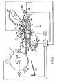
- Fig. 1 illustrates a duplex ink jet printer 10 incorporating a preferred embodiment of the sheet-registration and feeding apparatus of the invention.
- Printer 10 comprises a vacuum transport drum 12 which serves to transport sheets of paper past an ink jet print station 14.
- the transport drum and print station are of conventional design and constitute no part of this invention. It suffices to say, therefore, that these system components may be of the type disclosed in U.S. Patent No. 4,237,466.
- Drum 12 is rotatably driven in the direction indicated by arrow 16 by a motor M which is operatively connected to the drum's drive shaft 18.
- the print station As the drum rotates with paper on its surface, the print station is operated under the control of the printer's logic and control unit (LCU) and image information is recorded on that face of the sheet passing directly opposite the print station.
- LCU printer's logic and control unit
- the sheet Upon recording information on one face of the transported sheet, the sheet is stripped from the drum, reoriented, re-registered and returned to the drum so that printing may be effected on the opposite face thereof.
- LCU printer's logic and control unit
- Apparatus 20 comprises first feed means 22 for advancing sheets, one at a time, from a sheet supply 24 along a sheet path 26 leading toward the print station.
- Sheet path 26 is, in part, defined by a flat deck 28 which serves to support the sheets intermediate the sheet supply and the vacuum transport drum.
- a registration gate 30, located along the sheet path, is provided for registering the sheets moving therealong. Gate 30 is moveable (by means described below) from a position spaced from the sheet path to a registration position in which it intercepts the path and engages the leading edge of a sheet moving toward the transport drum.
- Second feed means 32 located upstream and in close proximity to the registration gate is selectively operable in one of three modes; i.e., first and second active modes and in a passive mode.
- feed means 32 functions to advance sheets, upon being registered by gate 30, to the surface of the vacuum transport drum where they are engaged by the drum and advanced along a sheet inverting path past the print station 14.
- the second feed means operates to receive sheets advanced thereto by the vacuum transport drum, and to advance such sheets in an upstream direction, away from the transport drum.
- the second feed means allows sheets to advance in a downstream direction without substantial interference.
- a chute 34 is positioned upstream of second feed means 32 to receive sheets advanced by the second feed means while operating in its second active mode.
- Chute 34 has an open end 36 through which sheets advanced by the second feed means enter the chute, and a closed end 38 which, as explained below, serves to arrest forward movement of a sheet within the chute before the trailing edge clears the second feed means. In this manner, the sheet is forced to buckle while positioned in the chute.
- Timing and control means 40 serves to control the movement of the registration gate and the mode of operation of the second feed means.
- the timing and control means may comprise for example a cam sequencer 42 and a plurality of cooperating cam-followers 44, 46 and 48 and associated linkages.
- second feed means 32 preferably comprises a pair of opposed rollers 50 and 52 which are mounted for rotation about spaced, parallel axes A and A', respectively.
- each of these rollers may itself comprise, as is common in the art, a plurality of individual rollers which are spaced apart and mounted for rotation on a common drive shaft.
- the upper surface of roller 50 protrudes through an aperture 28a in deck 28 so that sheets moving along the deck's upper surface contact the roller's surface substantially tangentially.
- Roller 50 is selectively driven in either clockwise or counterclockwise directions by a bi-directional motor 54 which operates under the control of the printer's logic and control unit (LCU).
- Roller 52 is an idler roller which is rotatably mounted on a shaft 56.
- the latter and its associated roller 52 are moveable between a position in which roller 52 contacts roller 50 and cooperates to define a nip for advancing sheets therebetween, and a position in which roller 52 is sufficiently spaced from roller 50 as to allow sheets to advance therebetween with substantially no interference.
- the position of roller 52 and the direction of rotation of roller 50 determine the mode of operation of second feed means 32.
- the second feed means When the rollers are spaced apart, the second feed means, of course, is in its passive mode; when rollers 50 and 52 engage, the second feed means is in one of its active modes.
- the mode of operation of the second feed means is controlled by the logic and control unit (LCU), which controls both the cam sequencer 42 and the bi-directional motor 54.
- feed means 22 functions to a feed sheet S from supply 24 along deck 28 toward drum 12.
- the cam sequencer 42 acts through cam followers 44 and 46 to position the registration gate 30 in the sheet path and to switch the second feed means 32 to its passive mode, i.e., to space roller 52 from roller 50.
- the leading edge of sheet S passes freely between the rollers and is guided to the registration gate by the combination of deck 28 and an arcuate guide plate 58 which guides the sheet from above.
- Deck 28 and guide plate 58 cooperate to define a converging guideway 59 having its narrowest opening in the region between the rollers.
- Guide plate 58 is provided with an aperture 58a through which roller 52 can move into contact with roller 50, as explained below.
- a sheet sensor D e.g., a photoelectric sensor
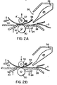
- the latter continues to operate the first feed means 22 until a slight buckle is formed in the sheet, assuring good registration of the leading edge across the entire feed path. (See Fig. 2A).
- second feed means 32 is switched to its first active mode.
- cam sequencer 42 acts, through cam follower 46, to move roller 52 through aperture 28a, toward engagement with roller 50. (See Fig. 2B).
- cam sequencer 42 acting through cam follower 44 removes the registration gate 30 from the sheet path, and the logic and control unit, acting through motor 54, rotates roller 50 in a counterclockwise direction.
- the second-feed means operates to advance sheets toward vacuum transport drum 12.
- a moveable guide member 60 is provided.
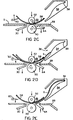
- Guide member 60 moves between a first position (Fig. 2C) in which it contacts the bottom surface of plate 58 and deflects sheets toward drum 12, and a second position (Fig. 2D) in which it deflects a sheet strip from drum 12 to the downstream side of the drive nip defined by rollers 50 and 52, as explained below.
- the position of guide member 60 is controlled by the cam sequencer through cam follower 48. (See Fig. 2C).
- a stripper finger 62 is moved to a position in which it acts to strip the leading edge of the sheet from the drum and deflect it upstream toward feed means 32.
- guide member 60 is moved, via cam follower 48, to its second position in which it functions to guide the leading edge of the stripped sheet back toward the roller nip.
- the direction of roller 50 is reversed and driven in a clockwise direction.
- a second guide member 64 is moved upwardly, through aperture 28a in deck 28, to the position as shown in Fig. 2D.
- second guide member 64 The position of second guide member 64 is also controlled by cam follower 48, acting through linkage arms 66 and 68.
- the function of second guide member 64 is to deflect the sheet's leading edge into chute 34.
- sensor D As the sheet enters chute 34, its presence is sensed by sensor D which signals the logic and control unit to begin to decelerate the rotation of roller 50.
- the leading edge reaches the chute's closed end 38 where further movement away from the roller nip is arrested.
- roller 50 continues rotating at a reduced speed, the sheet's trailing edge moves toward the now stationary leading edge, the result being that the sheet buckles, as shown in Fig. 2E.
- the cam sequencer 42 acting through cam follower 44, returns the registration gate to a position intercepting the feed path. (See Fig. 2F). Thereafter, the cam sequencer, acting through cam follower 46, switches the second feed means to its passive mode, positioning roller 52 in a position spaced from roller 50. At this time, the former trailing edge of the sheet, which is now the leading edge, will be propelled through the space separating the rollers and into engagement with the registration gate. (See Fig. 2G).
- the spacing between the registration position and the closed end of the chute is slightly less than the spacing between the lead and trail edges of the sheet, whereby the sheet remains slightly buckled at the registration gate.
- the cam sequencer returns the second feed means to its first active mode, moving roller 52 into engagement with roller 50, and the sheet is again returned to the transport drum to receive an image on the opposite face thereof.
- the duplex process is completed and the sheet is stripped from the drum by a stripper finger 70 which deflects the leading edge into an exit hopper 72.
- the sheet-registration and feeding apparatus of the invention overcomes the aforementioned disadvantages of the similar prior art mechanisms.
- the restoring forces in the sheet will propel the sheet to its registration position without contact by any feed elements which might otherwise alter the sheet's course.
- control over the sheet is always maintained inasmuch as the sheet, during and after the buckling procedure, never leaves the nip between rollers 50 and 52.
- the apparatus of the invention is also advantageous from the standpoint that the duplex feed path shares the same feeding and guiding elements as the simplex feed path, thereby minimizing path length and cost, and maximizing efficiency.
Landscapes
- Physics & Mathematics (AREA)
- General Physics & Mathematics (AREA)
- Registering Or Overturning Sheets (AREA)
- Delivering By Means Of Belts And Rollers (AREA)
- Separation, Sorting, Adjustment, Or Bending Of Sheets To Be Conveyed (AREA)
Applications Claiming Priority (2)
| Application Number | Priority Date | Filing Date | Title |
|---|---|---|---|
| US06/751,655 US4645195A (en) | 1985-07-03 | 1985-07-03 | Sheet-registration and feeding apparatus |
| US751655 | 1985-07-03 |
Publications (2)
| Publication Number | Publication Date |
|---|---|
| EP0207425A2 true EP0207425A2 (de) | 1987-01-07 |
| EP0207425A3 EP0207425A3 (de) | 1988-03-02 |
Family
ID=25022933
Family Applications (1)
| Application Number | Title | Priority Date | Filing Date |
|---|---|---|---|
| EP86108586A Withdrawn EP0207425A3 (de) | 1985-07-03 | 1986-06-24 | Blattbestimmungs- und Zuführungsgerät |
Country Status (3)
| Country | Link |
|---|---|
| US (1) | US4645195A (de) |
| EP (1) | EP0207425A3 (de) |
| JP (1) | JPS6212553A (de) |
Cited By (2)
| Publication number | Priority date | Publication date | Assignee | Title |
|---|---|---|---|---|
| EP0324544A3 (en) * | 1988-01-15 | 1990-06-27 | Xerox Corporation | Copying machine |
| CN104191833A (zh) * | 2014-08-25 | 2014-12-10 | 浪潮软件集团有限公司 | 一种打印机用送纸器 |
Families Citing this family (21)
| Publication number | Priority date | Publication date | Assignee | Title |
|---|---|---|---|---|
| DE3521590C1 (de) * | 1985-06-15 | 1986-08-21 | M.A.N.- Roland Druckmaschinen AG, 6050 Offenbach | Bogenglaetteinrichtung fuer die Greiferkante eines Bogens an der Bogenanlage einer Bogenrotationsdruckmaschine |
| JP2560714B2 (ja) * | 1987-03-09 | 1996-12-04 | ミノルタ株式会社 | 用紙搬送装置 |
| JPH01281970A (ja) * | 1988-05-10 | 1989-11-13 | Mitsubishi Electric Corp | 印字装置 |
| US4882989A (en) * | 1989-02-08 | 1989-11-28 | Pitney Bowes Inc. | Mailing machine including improved sheet aligning means |
| US4982207A (en) * | 1989-10-02 | 1991-01-01 | Eastman Kodak Company | Heating print-platen construction for ink jet printer |
| GB8929365D0 (en) * | 1989-12-30 | 1990-02-28 | Alcatel Business Systems | Article feeding |
| US5184988A (en) * | 1990-01-10 | 1993-02-09 | Precor Incorporated | Exercise treadmill |
| GB2259501B (en) * | 1991-09-11 | 1995-04-12 | Xerox Corp | Electrostatographic reproducing machine |
| US5495103A (en) * | 1994-03-16 | 1996-02-27 | Ascom Hasler Mailing Systems Ag | Optical mail piece sensor for postage meter |
| US5658416A (en) * | 1994-06-17 | 1997-08-19 | Polaroid Corporation | Method and apparatus for peeling a laminate |
| CH690715A5 (de) * | 1995-07-27 | 2000-12-29 | Ferag Ag | Fördereinrichtung für Druckereierzeugnisse. |
| US5730055A (en) * | 1996-02-08 | 1998-03-24 | Heidelberger Druckmaschinen Ag | Sheet guiding device for printing presses |
| US6018640A (en) * | 1999-03-31 | 2000-01-25 | Hewlett-Packard Company | Image alignment during duplex printing |
| US6167231A (en) * | 1999-03-31 | 2000-12-26 | Hewlett-Packard Company | Print recording apparatus having modular autoduplex mechanism |
| EP1610260A3 (de) * | 1999-10-05 | 2006-02-01 | Seiko Epson Corporation | Zweiseitiger Druck in einem Tintenstrahldrucker |
| US7097593B2 (en) | 2003-08-11 | 2006-08-29 | Nautilus, Inc. | Combination of treadmill and stair climbing machine |
| US7643161B2 (en) * | 2004-10-27 | 2010-01-05 | Hewlett-Packard Development Company, L.P. | Inter-device media handler |
| NL1030709C2 (nl) * | 2005-12-20 | 2007-06-21 | Oce Tech Bv | Veltransportinrichting en printer voorzien van een dergelijke inrichting. |
| JP4750754B2 (ja) * | 2007-05-31 | 2011-08-17 | 株式会社リコー | シート搬送装置および画像形成装置 |
| JP5064518B2 (ja) * | 2010-01-19 | 2012-10-31 | 京セラドキュメントソリューションズ株式会社 | 自動原稿搬送装置、及びこれを備えた画像形成装置 |
| KR20120015513A (ko) * | 2010-08-12 | 2012-02-22 | 주식회사 비즈테크원 | 버퍼기능을 구비한 용지반송장치 및 용지반송방법 |
Family Cites Families (11)
| Publication number | Priority date | Publication date | Assignee | Title |
|---|---|---|---|---|
| US3856295A (en) * | 1973-12-28 | 1974-12-24 | Xerox Corp | Inverter-reverser for a reproduction machine |
| US4186662A (en) * | 1977-08-22 | 1980-02-05 | A. B. Dick Company | Duplexing copying system |
| JPS5561538A (en) * | 1978-10-27 | 1980-05-09 | Fujitsu Ltd | Automatic paper feeding apparatus |
| US4223886A (en) * | 1979-04-16 | 1980-09-23 | Eastman Kodak Company | Registration gate mechanism for recirculating document feeder and document positioner |
| US4237466A (en) * | 1979-05-07 | 1980-12-02 | The Mead Corporation | Paper transport system for an ink jet printer |
| US4262895A (en) * | 1979-08-31 | 1981-04-21 | Xerox Corporation | Inverter with variable buckling control |
| US4359217A (en) * | 1980-09-02 | 1982-11-16 | Xerox Corporation | Inverter with proportional force paper drive |
| JPS57189951A (en) * | 1981-05-20 | 1982-11-22 | Hitachi Ltd | System to prevent skew |
| JPS5821270A (ja) * | 1981-07-30 | 1983-02-08 | Minolta Camera Co Ltd | 記録装置 |
| JPS58100047A (ja) * | 1981-12-11 | 1983-06-14 | Fuji Xerox Co Ltd | レジストレ−シヨン装置 |
| NL8202399A (nl) * | 1982-06-14 | 1984-01-02 | Oce Nederland Bv | Omkeerinrichting voor bladen. |
-
1985
- 1985-07-03 US US06/751,655 patent/US4645195A/en not_active Expired - Fee Related
-
1986
- 1986-06-24 EP EP86108586A patent/EP0207425A3/de not_active Withdrawn
- 1986-07-03 JP JP61157177A patent/JPS6212553A/ja active Pending
Cited By (2)
| Publication number | Priority date | Publication date | Assignee | Title |
|---|---|---|---|---|
| EP0324544A3 (en) * | 1988-01-15 | 1990-06-27 | Xerox Corporation | Copying machine |
| CN104191833A (zh) * | 2014-08-25 | 2014-12-10 | 浪潮软件集团有限公司 | 一种打印机用送纸器 |
Also Published As
| Publication number | Publication date |
|---|---|
| US4645195A (en) | 1987-02-24 |
| EP0207425A3 (de) | 1988-03-02 |
| JPS6212553A (ja) | 1987-01-21 |
Similar Documents
| Publication | Publication Date | Title |
|---|---|---|
| US4645195A (en) | Sheet-registration and feeding apparatus | |
| US5449164A (en) | Sheet inverter apparatus | |
| US5008713A (en) | Sheet conveying apparatus and sheet conveying method | |
| EP0576235B1 (de) | Ausgabevorrichtung zum Stapeln von Bögen mit deren Vorderseite nach oben oder unter mit einem auf einer Kreisbahn in mehrere Stellungen bringbaren Walzenspalt | |
| US4049256A (en) | Document alignment assembly | |
| US4805892A (en) | Cross-track registration device for sheet transport system | |
| US5055885A (en) | Picture image forming equipment | |
| US4789150A (en) | Sheet stacking apparatus with trail edge control flaps | |
| US7003257B2 (en) | Hole-punching processor and image forming apparatus | |
| US6394446B1 (en) | Reverse feeding device | |
| CA1047970A (en) | Separator card retriever | |
| US4146220A (en) | Document handling apparatus | |
| US5449160A (en) | Gateless rocker inverter | |
| US5447303A (en) | Sheet inverter apparatus | |
| US4456238A (en) | Duplex tray for duplex copying machine and the like | |
| JP4869663B2 (ja) | シート反転/給送機及びシート給送方法 | |
| US4076233A (en) | Document handling apparatus | |
| JPH0259095B2 (de) | ||
| JP3404142B2 (ja) | 用紙姿勢制御装置 | |
| JP2002068574A (ja) | 後処理装置 | |
| JPH06156850A (ja) | シート搬送経路切換え装置 | |
| JP2710421B2 (ja) | 原稿自動給排装置 | |
| JPS58172154A (ja) | 用紙反転装置 | |
| JPS62121169A (ja) | 用紙排出装置 | |
| JPS60124272A (ja) | 紙送り機構 |
Legal Events
| Date | Code | Title | Description |
|---|---|---|---|
| PUAI | Public reference made under article 153(3) epc to a published international application that has entered the european phase |
Free format text: ORIGINAL CODE: 0009012 |
|
| AK | Designated contracting states |
Kind code of ref document: A2 Designated state(s): DE FR GB NL |
|
| PUAL | Search report despatched |
Free format text: ORIGINAL CODE: 0009013 |
|
| AK | Designated contracting states |
Kind code of ref document: A3 Designated state(s): DE FR GB NL |
|
| 17P | Request for examination filed |
Effective date: 19880803 |
|
| STAA | Information on the status of an ep patent application or granted ep patent |
Free format text: STATUS: THE APPLICATION HAS BEEN WITHDRAWN |
|
| 18W | Application withdrawn |
Withdrawal date: 19890616 |
|
| RIN1 | Information on inventor provided before grant (corrected) |
Inventor name: SPEHRLEY, CHARLES W., JR. Inventor name: SCRANTON, ROBERT J. |