EP0207446A1 - Vorrichtung zum Regenerieren eines Partikelfilters für Dieselmotoren - Google Patents
Vorrichtung zum Regenerieren eines Partikelfilters für Dieselmotoren Download PDFInfo
- Publication number
- EP0207446A1 EP0207446A1 EP86108706A EP86108706A EP0207446A1 EP 0207446 A1 EP0207446 A1 EP 0207446A1 EP 86108706 A EP86108706 A EP 86108706A EP 86108706 A EP86108706 A EP 86108706A EP 0207446 A1 EP0207446 A1 EP 0207446A1
- Authority
- EP
- European Patent Office
- Prior art keywords
- fuel
- combustion chamber
- air
- pressure
- inlet
- Prior art date
- Legal status (The legal status is an assumption and is not a legal conclusion. Google has not performed a legal analysis and makes no representation as to the accuracy of the status listed.)
- Granted
Links
Images

Classifications
-
- F—MECHANICAL ENGINEERING; LIGHTING; HEATING; WEAPONS; BLASTING
- F01—MACHINES OR ENGINES IN GENERAL; ENGINE PLANTS IN GENERAL; STEAM ENGINES
- F01N—GAS-FLOW SILENCERS OR EXHAUST APPARATUS FOR MACHINES OR ENGINES IN GENERAL; GAS-FLOW SILENCERS OR EXHAUST APPARATUS FOR INTERNAL-COMBUSTION ENGINES
- F01N3/00—Exhaust or silencing apparatus having means for purifying, rendering innocuous, or otherwise treating exhaust
- F01N3/02—Exhaust or silencing apparatus having means for purifying, rendering innocuous, or otherwise treating exhaust for cooling, or for removing solid constituents of, exhaust
- F01N3/021—Exhaust or silencing apparatus having means for purifying, rendering innocuous, or otherwise treating exhaust for cooling, or for removing solid constituents of, exhaust by means of filters
- F01N3/023—Exhaust or silencing apparatus having means for purifying, rendering innocuous, or otherwise treating exhaust for cooling, or for removing solid constituents of, exhaust by means of filters using means for regenerating the filters, e.g. by burning trapped particles
- F01N3/025—Exhaust or silencing apparatus having means for purifying, rendering innocuous, or otherwise treating exhaust for cooling, or for removing solid constituents of, exhaust by means of filters using means for regenerating the filters, e.g. by burning trapped particles using fuel burner or by adding fuel to exhaust
- F01N3/0253—Exhaust or silencing apparatus having means for purifying, rendering innocuous, or otherwise treating exhaust for cooling, or for removing solid constituents of, exhaust by means of filters using means for regenerating the filters, e.g. by burning trapped particles using fuel burner or by adding fuel to exhaust adding fuel to exhaust gases
- F01N3/0256—Exhaust or silencing apparatus having means for purifying, rendering innocuous, or otherwise treating exhaust for cooling, or for removing solid constituents of, exhaust by means of filters using means for regenerating the filters, e.g. by burning trapped particles using fuel burner or by adding fuel to exhaust adding fuel to exhaust gases the fuel being ignited by electrical means
-
- F—MECHANICAL ENGINEERING; LIGHTING; HEATING; WEAPONS; BLASTING
- F01—MACHINES OR ENGINES IN GENERAL; ENGINE PLANTS IN GENERAL; STEAM ENGINES
- F01N—GAS-FLOW SILENCERS OR EXHAUST APPARATUS FOR MACHINES OR ENGINES IN GENERAL; GAS-FLOW SILENCERS OR EXHAUST APPARATUS FOR INTERNAL-COMBUSTION ENGINES
- F01N2390/00—Arrangements for controlling or regulating exhaust apparatus
- F01N2390/02—Arrangements for controlling or regulating exhaust apparatus using electric components only
-
- F—MECHANICAL ENGINEERING; LIGHTING; HEATING; WEAPONS; BLASTING
- F02—COMBUSTION ENGINES; HOT-GAS OR COMBUSTION-PRODUCT ENGINE PLANTS
- F02B—INTERNAL-COMBUSTION PISTON ENGINES; COMBUSTION ENGINES IN GENERAL
- F02B3/00—Engines characterised by air compression and subsequent fuel addition
- F02B3/06—Engines characterised by air compression and subsequent fuel addition with compression ignition
Definitions
- the present invention relates generally to a system for regenerating emission filters and, more particularly, to such a system for use in a Diesel engine.
- Particulate matter such as carbon are contained in the exhaust gases of a Diesel engine, and removal of these particulates typically is accomplished by a particulate filter disposed in an exhaust pipe.
- a particulate filter is formed, for example, from ceramics formed with a number of slots arranged to collect the particulates as exhaust gases flow through in a circuitous fashion. After an extended period of use, conventional particulate filters become clogged and require regeneration.
- An improved regeneration system is disclosed in Japanese Patent Application. Laid-Open No. 128912/84.
- a combustor is arranged at the inlet of a particulate filter, and generates high temperature combustion gases for burning the particulates.
- Fuel is supplied to the combustor by an injection device and is mixed with air for combustion.
- vaporization is not promoted by mere spray mixing with air so that the fuel often is supplied to the combustor in the form of droplets. Consequently, combustion produces smoke of high concentration in the combustor, further contaminating the particulate filter.
- a back-flow type vaporization cylinder is employed to utilize fully the heat of exhaust gases.
- the vaporization cylinder requires the energy of hot exhaust gases produced during high load operation of the engine, and the particulate filter is not regenerated during low load engine operation.
- the combustor is operated only when two conditions are met; i.e., when the change rate of pressure at the inlet is below a first predetermined value, and when the pressure at the inlet side is above a second predetermined value. Therefore, during operation attended by frequent acceleration and deceleration experienced in hilly terrain, the combustion state in the engine deteriorates resulting in an increase in exhaust gases and operation of the regeneration combustor is intermittent. Accordingly, the particulate filter cannot be regenerated properly and becomes clogged.
- the object of the present invention is to provide an improved system for regenerating a particulate filter in a Diesel engine.
- the invention is an emissions filter regeneration system including a particulate matter filter having an inlet connected by an exhaust pipe to an exhaust manifold of an engine, a pressure sensor disposed to sense the pressure at the inlet of the filter, a combustion chamber having an outlet opening disposed to discharge gases into the inlet, a fuel supply means for introducing fuel into the combustion chamber, an air supply means for introducing air into the combustion chamber, and an igniter for igniting a fuel and air mixture in the combustion chamber. Also included is a control means for activating the fuel supply means, the air supply means, and the igniter in response to sensing by the pressure sensor of a pressure above a predetermined value.
- the system also includes a temperature sensor disposed to sense the temperature of the discharged gases, and the control means deactivates the igniter means in response to sensing by the temperature sensor of temperatures above a given value.
- the temperature sensor deactivates the igniter when combustion in the combustion chamber is insured.
- the system includes a vaporization means disposed in the combustion chamber and comprising an electrical heater embedded in a flow distribution plate.
- the vaporization means vaporizes fuel injected into the combustion chamber so as to promote complete combustion thereof.
- the combustion chamber comprises a cylindrical portion disposed in the exhaust pipe, and the air supply means comprises an annular air chamber surrounding the combustion chamber and supplying air thereto.
- the air chamber also is disposed in the exhaust pipe so as to produce heating of air by the exhaust gases therein.
- the invention includes a revolution sensor for sensing the operating revolutions of the engine, and the control means controls the fuel supply means, the air supply means and the igniter in response to outputs from both the pressure sensor and the revolution sensor. Responding to both inlet pressure and engine r.p.m.s improves the performance of the system.
- the present invention is illustrated schematically in Fig. 1 in which an exhaust pipe 1 is connected between an exhaust manifold (not shown) of a Diesel engine and a particulate filter 2.
- the filter 2 has a plurality of slots formed from ceramics and is retained in a housing 1a whose outside diameter is enlarged. Disposed within the pipe 1 and the housing 1a, respectively, at the inlet of the particulate filter 2 are a pressure sensor 4 and a combustor A.
- a combustion cylinder 19 and a cylindrical housing 3 that surrounds the cylinder 19 and forms an annular air chamber 5. Outside air is introduced into the air chamber 5 by a blower 7 through an air intake duct 6.
- One end of the combustion cylinder 19 is closed and retains a fuel vaporization device 8 including a flow adjusting plate 10 having a number of holes formed from ceramics or the like.
- the plate 10 divides the combustion cylinder 19 into a combustion chamber 17 and a vaporization chamber 16.
- Fuel is supplied to the vaporization chamber 16 by a fuel pipe 20 having a jet and supported between the end wall of the combustion cylinder 19 and the flow adjusting plate 10.
- a fuel valve 15 is connected to an outer end of the fuel pipe 20 and to a fuel tank 13 by a fuel supply pipe 9. Fuel is heated in the vaporization device 8 by a heating coil embedded in the flow adjusting plate 10.
- Either a firing or a spark ignition plug 11 extends through the air chamber 5 and is disposed in the combustion chamber 17.
- Air in the air chamber 5 is preheated by the exhaust gases in the exhaust pipe 1 and is supplied to the vaporization chamber 16 and the combustion chamber 17 through air ports in the combustion cylinder 19.
- An outlet end of the combustion cylinder 19 opens adjacent to the center of the inlet to the particulate filter 2.
- Mounted internally of the combustion cylinder 19 is a temperature sensor 30 that discriminates as to whether or not fuel is fired within the chamber 17.
- a sensor 31 detects the number of revolutions of the Diesel engine (not shown) connected to the exhaust pipe 1.
- the operation of the combustor A is controlled by a control device 12 that receives input signals from the pressure sensor 4, the revolution sensor 31 and the temperature sensor 30. Outputs from the control device 12 are applied to the blower 7, the plug 11, the heating coil in the flow adjusting plate 10 and the fuel valve 15.
- the control device 12 is composed, for example, of a microcomputer, and a signal from the pressure sensor 4 is applied as a digital signal to the control device 12 through an A/D converter (not shown).
- Pressure at the inlet of the particulate filter 2 is always detected by the pressure sensor 4, and an output signal indicative thereof is fed to the control device 12.
- the signal value increases proportional to the inlet pressure, and when this signal value becomes greater than a reference value Po, the control device 12 initially energizes the ignition plug 11 and the heater embedded in the plate 10 to prepare the combustor A for operation. Subsequently, the control device 12 activates the blower 7 and the valve 15. Energization of the blower 7 causes outside air to be fed from the air intake duct 6 into the air chamber 5. Preheating of the outside air is provided by the exhaust gases passing through the pipe 1 outside the housing 3.
- the air then is supplied from the air chamber 5 into the vaporization chamber 16 and combustion chamber 17, respectively, through air ports in the combustion cylinder 19. Also, opening of the valve 15 causes fuel in the fuel tank 13 to flow through the fuel supply pipe 9 and the fuel pipe 20 of the fuel vaporization device 8. The supplied fuel is discharged by a jet into the vaporization chamber 16, where it is mixed with air and fed into the combustion chamber 17 through the holes in the flow adjusting plate 10. Thus, a mixture of fuel and air is fed into the combustion chamber 17, and when heated to a firing temperature by the firing plug 11, combustion occurs. Resultant combustion gases pass through the combustion cylinder 19 and enter and regenerate the particulate filter 2 by burning the particulates collected therein.
- the control device deenergizes the blower 7, the ignition plug 11, the fuel valve 15 and the heating coil in the flow adjusting plate 10 to thereby terminate operation of the combustor A.
- the allowable discharge pressure Po(reference level) of the combustor A at the inlet of the particulate filter 2 is determined by the control device 12 as shown in Fig. 2.
- the inlet pressure during regeneration is increased by the output of the combustor A but when the particulates are removed from the filter 2, the pressure decreases to a level below the allowable pressure.
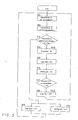
- Fig. 3 is a flow diagram showing the software program for a microcomputer in the control device 12.
- step p11 the rate of revolutions of the engine is read, and a reference level Po corresponding thereto is determined from the control map (Fig. 2) stored in a ROM of the microcomputer.
- step p12 the detected pressure P of the pressure sensor 4 at the inlet of the particulate filter 2 is read.
- step p13 the detected pressure P is compared to the determined reference level Po. If the detected inlet pressure P is less than the reference level Po, the control device proceeds to step p19 and the fuel valve 15 is closed.
- step p20 the heating coil in the flow adjusting plate 10, the ignition plug11 and the blower 7 are in a de-energized state.
- step p13 the detected inlet pressure P exceeds the reference level Po
- the control device 12 proceeds to step p14 where the ignition plug 11 is energized.
- step p15 the fuel valve 15 is opened; in step p16, the heating coil in the flow adjusting plate 10 is energized; and in step p17, the signal value t of the temperature sensor 30 is compared to a reference value t o . If the temperature t in the combustion chamber 17 is greater than the reference value t o a determination is made that the fuel was fired and in step p18, energization to the firing plug 11 is terminated.
- fuel vaporization means are included, disposed in said combustion chamber so as to vaporize fuel injected thereinto by said fuel supply means.
- fuel vaporization means comprises electrical heating means.
- fuel vaporization means further comprises a flow distribution means.
- ignition means comprises an ignition plug
- air supply means comprises a blower
- control means comprises a computer.
- a revolution sensor is included for detecting the revolution rate of the engine, and said control means adjusts said predetermined value of said pressure dependent on the output received from said revolution sensor.
- a temperature sensor is disposed to sense the temperature of said discharged gases, and wherein said control means deactivates said ignition means in response to sensing by said temperature sensor of temperatures above a given value.
- said fuel vaporization means are including means disposed in said combustion chamber so as to vaporize fuel injected thereinto by said fuel supply means. Further in that said control means activates said ignition means prior to activation of said fuel supply means.
- a temperature sensor is disposed to sense the temperature of said discharged gases, and wherein said control means deactivates said ignition means in response to sensing by said temperature sensor of temperatures above a given value.
- fuel vaporization means are disposed in said combustion chamber so as to vaporize fuel injected thereinto by said fuel supply means.
- a revolution sensor is included for detecting the revolution rate of the engine, and said control means adjusts said predetermined value of said pressure dependent on the output received from said revolution sensor.
- the engine is a Diesel engine.
- the invention is also concerned with a method to operate a particulate matter filter having an imission filter regeneration system, characterized in that the regeneration system is operated only when the pressure level at an inlet of the filter exceeds a predetermined pressure level.
Landscapes
- Engineering & Computer Science (AREA)
- Chemical & Material Sciences (AREA)
- Combustion & Propulsion (AREA)
- Mechanical Engineering (AREA)
- General Engineering & Computer Science (AREA)
- Processes For Solid Components From Exhaust (AREA)
- Exhaust Gas After Treatment (AREA)
Applications Claiming Priority (2)
| Application Number | Priority Date | Filing Date | Title |
|---|---|---|---|
| JP137838/85 | 1985-06-26 | ||
| JP13783885A JPH0621545B2 (ja) | 1985-06-26 | 1985-06-26 | 排気微粒子濾過器の再生装置 |
Publications (2)
| Publication Number | Publication Date |
|---|---|
| EP0207446A1 true EP0207446A1 (de) | 1987-01-07 |
| EP0207446B1 EP0207446B1 (de) | 1989-06-14 |
Family
ID=15208005
Family Applications (1)
| Application Number | Title | Priority Date | Filing Date |
|---|---|---|---|
| EP86108706A Expired EP0207446B1 (de) | 1985-06-26 | 1986-06-26 | Vorrichtung zum Regenerieren eines Partikelfilters für Dieselmotoren |
Country Status (5)
| Country | Link |
|---|---|
| US (1) | US4711087A (de) |
| EP (1) | EP0207446B1 (de) |
| JP (1) | JPH0621545B2 (de) |
| CA (1) | CA1296265C (de) |
| DE (1) | DE3663975D1 (de) |
Cited By (3)
| Publication number | Priority date | Publication date | Assignee | Title |
|---|---|---|---|---|
| EP0283240A3 (en) * | 1987-03-20 | 1989-01-25 | Matsushita Electric Industrial Co., Ltd. | A purifier of diesel particulates in exhaust gas |
| EP2878776A4 (de) * | 2012-06-15 | 2015-09-02 | Hino Motors Ltd | Brenner für eine abgasreinigungsvorrichtung |
| US9206736B2 (en) | 2012-12-28 | 2015-12-08 | Makita Corporation | Stratified scavenging two-stroke engine |
Families Citing this family (14)
| Publication number | Priority date | Publication date | Assignee | Title |
|---|---|---|---|---|
| US5572866A (en) * | 1994-04-29 | 1996-11-12 | Environmental Thermal Oxidizers, Inc. | Pollution abatement incinerator system |
| US6138454A (en) * | 1998-12-18 | 2000-10-31 | Daimlerchrysler Corporation | Selective catalyst reduction wit pox reactor for engine exhaust aftertreatment |
| US6405528B1 (en) * | 2000-11-20 | 2002-06-18 | Ford Global Technologies, Inc. | Method for determining load on particulate filter for engine exhaust, including estimation of ash content |
| DE10106503A1 (de) * | 2001-02-13 | 2002-08-29 | Bosch Gmbh Robert | Vorrichtung und Verfahren zur nachmotorischen Einbringung eines Hilfsmittels in einen Abgasstrom |
| US7025811B2 (en) * | 2002-08-23 | 2006-04-11 | Cleaire Advanced Emission Controls | Apparatus for cleaning a diesel particulate filter with multiple filtration stages |
| US7481048B2 (en) * | 2005-06-30 | 2009-01-27 | Caterpillar Inc. | Regeneration assembly |
| US20070158466A1 (en) * | 2005-12-29 | 2007-07-12 | Harmon Michael P | Nozzle assembly |
| US20070228191A1 (en) * | 2006-03-31 | 2007-10-04 | Caterpillar Inc. | Cooled nozzle assembly for urea/water injection |
| US20070235556A1 (en) * | 2006-03-31 | 2007-10-11 | Harmon Michael P | Nozzle assembly |
| US8209969B2 (en) * | 2006-06-15 | 2012-07-03 | Delphi Technologies, Inc. | Method and apparatus for burning reformate in an engine exhaust stream |
| RU2466281C1 (ru) | 2008-09-24 | 2012-11-10 | Макита Корпорейшн | Двухтактный двигатель с послойной продувкой |
| JP2010229876A (ja) * | 2009-03-26 | 2010-10-14 | Sumitomo (Shi) Construction Machinery Co Ltd | 建設機械のフィルタ再生装置 |
| US8656708B2 (en) * | 2011-01-31 | 2014-02-25 | Tenneco Automotive Operating Company Inc. | Coaxial inlet and outlet exhaust treatment device |
| CN107152331A (zh) * | 2017-06-02 | 2017-09-12 | 中国第汽车股份有限公司 | 基于燃烧器的dpf主动再生状态机控制方法 |
Citations (6)
| Publication number | Priority date | Publication date | Assignee | Title |
|---|---|---|---|---|
| FR2396163A1 (fr) * | 1977-06-30 | 1979-01-26 | Texaco Development Corp | Filtre de fumee pour moteur a combustion interne |
| US4404795A (en) * | 1980-06-19 | 1983-09-20 | Toyota Jidosha Kogyo Kabushiki Kaisha | Method of and apparatus for reducing emitted amount of particulates contained in exhaust gas of diesel engine |
| US4424671A (en) * | 1981-02-20 | 1984-01-10 | Nissan Motor Company, Limited | Exhaust gas particle burning method and apparatus for an internal combustion engine |
| EP0114696A2 (de) * | 1983-01-24 | 1984-08-01 | Hitachi, Ltd. | Verfahren und Einrichtung zur Steuerung der Abgasentgiftung für Dieselmotoren |
| GB2134408A (en) * | 1983-02-03 | 1984-08-15 | Ford Motor Co | Method for regenerating a diesel engine exhaust filter |
| US4589254A (en) * | 1983-07-15 | 1986-05-20 | Mitsubishi Jidosha Kogyo Kabushiki Kaisha | Regenerator for diesel particulate filter |
Family Cites Families (3)
| Publication number | Priority date | Publication date | Assignee | Title |
|---|---|---|---|---|
| US4462208A (en) * | 1982-09-23 | 1984-07-31 | General Motors Corporation | Regeneration control system for a diesel engine exhaust particulate filter |
| US4566271A (en) * | 1982-12-01 | 1986-01-28 | Lucas Industries Public Limited Company | Engine systems |
| US4610138A (en) * | 1983-09-26 | 1986-09-09 | Nissan Motor Company, Limited | Exhaust particle removing system for an internal combustion engine |
-
1985
- 1985-06-26 JP JP13783885A patent/JPH0621545B2/ja not_active Expired - Lifetime
-
1986
- 1986-06-23 US US06/877,493 patent/US4711087A/en not_active Expired - Fee Related
- 1986-06-26 CA CA000512541A patent/CA1296265C/en not_active Expired - Fee Related
- 1986-06-26 EP EP86108706A patent/EP0207446B1/de not_active Expired
- 1986-06-26 DE DE8686108706T patent/DE3663975D1/de not_active Expired
Patent Citations (6)
| Publication number | Priority date | Publication date | Assignee | Title |
|---|---|---|---|---|
| FR2396163A1 (fr) * | 1977-06-30 | 1979-01-26 | Texaco Development Corp | Filtre de fumee pour moteur a combustion interne |
| US4404795A (en) * | 1980-06-19 | 1983-09-20 | Toyota Jidosha Kogyo Kabushiki Kaisha | Method of and apparatus for reducing emitted amount of particulates contained in exhaust gas of diesel engine |
| US4424671A (en) * | 1981-02-20 | 1984-01-10 | Nissan Motor Company, Limited | Exhaust gas particle burning method and apparatus for an internal combustion engine |
| EP0114696A2 (de) * | 1983-01-24 | 1984-08-01 | Hitachi, Ltd. | Verfahren und Einrichtung zur Steuerung der Abgasentgiftung für Dieselmotoren |
| GB2134408A (en) * | 1983-02-03 | 1984-08-15 | Ford Motor Co | Method for regenerating a diesel engine exhaust filter |
| US4589254A (en) * | 1983-07-15 | 1986-05-20 | Mitsubishi Jidosha Kogyo Kabushiki Kaisha | Regenerator for diesel particulate filter |
Non-Patent Citations (4)
| Title |
|---|
| PATENTS ABSTRACTS OF JAPAN, vol. 8, no. 143 (M-306)[1580], 4th July 1984; & JP-A-59 41 620 (TOYO KOGYO K.K.) 07-03-1984 * |
| PATENTS ABSTRACTS OF JAPAN, vol. 8, no. 195 (M-323)[1632], 7th September 1984; & JP-A-59 85 417 (TOYOTA JIDOSHA K.K.) 17-05-1984 * |
| PATENTS ABSTRACTS OF JAPAN, vol. 8, no. 249 (M-338)[1686], 15th November 1984; & JP-A-59 126 015 (ISUZU JIDOSHA K.K.) 20-07-1984 * |
| PATENTS ABSTRACTS OF JAPAN, vol. 9, no. 80 (M-370)[1803], 10th April 1985; & JP-A-59 211 711 (NISSAN JIDOSHA K.K.) 30-11-1984 * |
Cited By (5)
| Publication number | Priority date | Publication date | Assignee | Title |
|---|---|---|---|---|
| EP0283240A3 (en) * | 1987-03-20 | 1989-01-25 | Matsushita Electric Industrial Co., Ltd. | A purifier of diesel particulates in exhaust gas |
| US4840028A (en) * | 1987-03-20 | 1989-06-20 | Matsushita Electric Industrial Co., Ltd. | Purifier of diesel particulates in exhaust gas |
| EP2878776A4 (de) * | 2012-06-15 | 2015-09-02 | Hino Motors Ltd | Brenner für eine abgasreinigungsvorrichtung |
| US9206736B2 (en) | 2012-12-28 | 2015-12-08 | Makita Corporation | Stratified scavenging two-stroke engine |
| US9869235B2 (en) | 2012-12-28 | 2018-01-16 | Makita Corporation | Stratified scavenging two-stroke engine |
Also Published As
| Publication number | Publication date |
|---|---|
| US4711087A (en) | 1987-12-08 |
| JPH0621545B2 (ja) | 1994-03-23 |
| EP0207446B1 (de) | 1989-06-14 |
| CA1296265C (en) | 1992-02-25 |
| JPS62616A (ja) | 1987-01-06 |
| DE3663975D1 (en) | 1989-07-20 |
Similar Documents
| Publication | Publication Date | Title |
|---|---|---|
| US4711087A (en) | Emissions filter regeneration system | |
| US4319896A (en) | Smoke filter rejuvenation system | |
| EP0114696B1 (de) | Verfahren und Einrichtung zur Steuerung der Abgasentgiftung für Dieselmotoren | |
| EP0380838B1 (de) | Ultraschallabbrennvorrichtung zur Regenerierung eines Filters | |
| US5044158A (en) | Process and device for closed-loop and open-loop control of the output of a burner | |
| US5950420A (en) | Method and arrangement for controlling exhaust emissions from an internal combustion engine | |
| GB1598172A (en) | Controllably heated smoke filter for internal combustion engine | |
| CN111734517A (zh) | 用于内燃机的废气后处理的装置和方法 | |
| EP2300133B1 (de) | Abgasbehandlungssystem mit regenerationssteuerung | |
| US4506506A (en) | Exhaust emission control device for diesel engine | |
| US8424291B2 (en) | Flame glow plug | |
| US4881369A (en) | Exhaust gas purifying apparatus | |
| US20100011743A1 (en) | Regeneration apparatus | |
| US4331454A (en) | Exhaust filter rejuvenation method | |
| US7434388B2 (en) | Method and system for regeneration of a particulate filter | |
| CN1929895B (zh) | 排放减少组件及其操作方法 | |
| GB2134408A (en) | Method for regenerating a diesel engine exhaust filter | |
| JPH11324650A (ja) | 黒煙除去装置 | |
| JPS62162762A (ja) | デイ−ゼル機関の排気ガス浄化装置 | |
| JPH066185Y2 (ja) | パ−ティキュレイトトラップフィルタの再生装置 | |
| DE3619397A1 (de) | Verfahren zum regenerieren eines russfilters und dieselmotor mit russabbrennfilter | |
| JPH0123647B2 (de) | ||
| JPH0137136Y2 (de) | ||
| JPH0115853Y2 (de) | ||
| JPH0447120A (ja) | エンジンの排気浄化装置 |
Legal Events
| Date | Code | Title | Description |
|---|---|---|---|
| PUAI | Public reference made under article 153(3) epc to a published international application that has entered the european phase |
Free format text: ORIGINAL CODE: 0009012 |
|
| AK | Designated contracting states |
Kind code of ref document: A1 Designated state(s): DE GB |
|
| 17P | Request for examination filed |
Effective date: 19870424 |
|
| 17Q | First examination report despatched |
Effective date: 19871112 |
|
| GRAA | (expected) grant |
Free format text: ORIGINAL CODE: 0009210 |
|
| AK | Designated contracting states |
Kind code of ref document: B1 Designated state(s): DE GB |
|
| REF | Corresponds to: |
Ref document number: 3663975 Country of ref document: DE Date of ref document: 19890720 |
|
| PLBE | No opposition filed within time limit |
Free format text: ORIGINAL CODE: 0009261 |
|
| STAA | Information on the status of an ep patent application or granted ep patent |
Free format text: STATUS: NO OPPOSITION FILED WITHIN TIME LIMIT |
|
| 26N | No opposition filed | ||
| PGFP | Annual fee paid to national office [announced via postgrant information from national office to epo] |
Ref country code: GB Payment date: 19940616 Year of fee payment: 9 |
|
| PGFP | Annual fee paid to national office [announced via postgrant information from national office to epo] |
Ref country code: DE Payment date: 19940622 Year of fee payment: 9 |
|
| PG25 | Lapsed in a contracting state [announced via postgrant information from national office to epo] |
Ref country code: GB Effective date: 19950626 |
|
| GBPC | Gb: european patent ceased through non-payment of renewal fee |
Effective date: 19950626 |
|
| PG25 | Lapsed in a contracting state [announced via postgrant information from national office to epo] |
Ref country code: DE Effective date: 19960301 |