EP0207511A2 - Antenne réseau à balayage électronique - Google Patents
Antenne réseau à balayage électronique Download PDFInfo
- Publication number
- EP0207511A2 EP0207511A2 EP86109023A EP86109023A EP0207511A2 EP 0207511 A2 EP0207511 A2 EP 0207511A2 EP 86109023 A EP86109023 A EP 86109023A EP 86109023 A EP86109023 A EP 86109023A EP 0207511 A2 EP0207511 A2 EP 0207511A2
- Authority
- EP
- European Patent Office
- Prior art keywords
- sum
- difference
- group antenna
- antenna according
- signals
- Prior art date
- Legal status (The legal status is an assumption and is not a legal conclusion. Google has not performed a legal analysis and makes no representation as to the accuracy of the status listed.)
- Granted
Links
Images



Classifications
-
- H—ELECTRICITY
- H01—ELECTRIC ELEMENTS
- H01Q—ANTENNAS, i.e. RADIO AERIALS
- H01Q3/00—Arrangements for changing or varying the orientation or the shape of the directional pattern of the waves radiated from an antenna or antenna system
- H01Q3/26—Arrangements for changing or varying the orientation or the shape of the directional pattern of the waves radiated from an antenna or antenna system varying the relative phase or relative amplitude of energisation between two or more active radiating elements; varying the distribution of energy across a radiating aperture
-
- H—ELECTRICITY
- H01—ELECTRIC ELEMENTS
- H01Q—ANTENNAS, i.e. RADIO AERIALS
- H01Q25/00—Antennas or antenna systems providing at least two radiating patterns
- H01Q25/02—Antennas or antenna systems providing at least two radiating patterns providing sum and difference patterns
Definitions
- the invention relates to a group antenna consisting of a multiplicity of line-fed, within the volume of an imaginary body which is symmetrical with respect to a horizontal plane and two perpendicularly intersecting vertical planes, in particular a sphere, distributed individual antennas with omnidirectional radiation pattern with electronically phase-controlled beam swiveling for radar all-round scanning.
- Such a group antenna is known from DE-PS 28 22 845. With this antenna, however, precise target location or target tracking is not possible.
- the monopulse antennas used hitherto correspond to an areal, non-spatial element arrangement in which four partial areas or partial antennas are combined into a sum, an elevation difference and an azimuth difference channel.
- the object of the invention is a spatially constructed group antenna of the type mentioned without intervention in the actual antenna configuration in such a way that an exact target location or target tracking is possible using the monopulse method.
- this object is achieved in that the individual emitters are divided into eight sub-volumes, so-called octants, which are delimited from one another by the three levels mentioned and fed separately in terms of signal, and in order to form a total sum signal, an elevation difference signal and two different azimuth difference signals the signals of the eight octants with a total of eleven elements, each forming sum and difference signals, such as ring hybrids, magic teas or the like.
- the sum and difference signals are first formed by two level adjacent octants, which are combined with the sum and difference signals of the neighboring pairs of octants so that finally the four desired sum and Differential signals of the eight octants are present.
- combination signals which can be designated as diagonal difference signals are also taken from some outputs, which are provided with a terminating resistor, of the elements forming the sum and difference signals, which result in radiation minima on the main axes given by the intersection lines of the three planes and in themselves to form the four desired ones Sum and difference signals are not required.
- the spatial distribution of the individual radiators, which fills the volume of the imaginary body, is advantageously such that the arrangement is as similar as possible for all directions.
- the individual radiators are expediently designed for horizontal polarization and the feed lines to the individual radiators run vertically.
- the individual radiators can be formed, for example, by horizontally lying conductor rings or by horizontally lying crossed dipoles in the manner of a turnstile ("turnstile") antennas.
- the sum-difference circuit For the implementation of the sum-difference circuit, a flat design is expedient, which can be implemented using stripline technology when transmitting lower powers, for example with exclusive reception mode or when using active single radiators. If the transmission mode with higher power is included in the sum channel, the sum-difference circuit can be implemented entirely or only on the sum channel paths in the form of a special coaxial line or waveguide system.
- Such a coaxial line system is known from DE-PS 27 01 228 and is characterized by an outer conductor which is formed by a flat, metal base plate, in which depressions are provided with a square or rectangular cross section corresponding to the desired line path, and which is covered by a plan-shaped cover plate which is mechanically and electrically connected to the base plate and is likewise made of metal, and by an inner conductor which is embedded in the recesses of the base plate and is supported therein by means of dielectric supports and which has a rectangular cross section with a constant height and has a width adapted according to the wave resistance requirement.
- An analog waveguide system for the sum-differential circuit also consists of a flat, metal base plate, in which depressions are provided with a square or rectangular cross-section corresponding to the desired line path, and of a planar design, with the base plate mechanically and electrically connected and also made of metal cover plate to cover the base plate.
- the recesses in the base plate of the coaxial line or waveguide system can be milled out in a computer-controlled manner in a cost-effective manner.
- FIG. 1 shows a cube which is symmetrical with respect to a horizontal plane E1 and two perpendicularly intersecting vertical planes E2 and E3 and which is intended to form an imaginary body 2, within the volume of which individual radiators with omnidirectional characteristics are to be distributed.
- the individual emitters within the cube are line-fed and form a group antenna with electronically phase-controlled beam swiveling for all-round radar scanning.
- the spatial distribution of the individual radiators which fills the volume of the imaginary body 2 is such that the arrangement is as similar as possible for all directions.
- the individual radiators are divided into eight sub-volumes V1 to V8, so-called octants, which are delimited from one another by the three levels E1, E2 and E3 and are fed separately in terms of signals.
- the signals occurring per octant V1 to V8 are also referred to as SV1 to SV8.
- the total sum signal ⁇ g , the elevation difference signal ⁇ E1 , and the two different azimuth difference signals ⁇ Az1 and ⁇ Az2 result from the following equations.
- ⁇ g SV1 + SV2 + SV3 + SV4 + SV5 + SV6 + SV7 + SV8 ⁇
- the signals SV1 to SV8 of the eight octants V1 to V8 are combined with a circuit of sum and difference-forming elements, such as ring hybrids, magic teas or the like.
- sum- and difference signals are first formed from the octane signals SV1 and SV2, SV3 and SV4, SV5 and SV6 as well as SV7 and SV8, that is to say from two octants which are adjacent with respect to the plane E3.
- the ring hybrids H1, H2, H3 and H4 are used for this.
- the sum and difference signals of the ring hybrids H1 and H2 are combined.
- sum and difference signals in turn arise at the outputs of the hybrids H5 and H6.
- the sum and difference signals of the hybrids H6 and H8 are further combined in two further hybrids H9 and H10, so that at the sum or difference output of the hybrid H9 the total sum signal ⁇ g or the elevation difference signal ⁇ E1 and at the sum output of the hybrid H10 that an azimuth difference signal ⁇ AZ1 is present.
- the differential output signals of the hybrids H5 and H7 are further combined in a hybrid H11, so that the second azimuth difference signal ⁇ Az2 is present at its sum output .
- the arrows at the empty outputs of the hybrids H5, H7, H10 and H11 each represent a terminating resistor.
- sum and difference signals are first formed from two octants each adjacent to plane E1.
- the hybrid H12 the sum and difference signals of the octane signals SV1 and SV5
- the hybrid H13 the sum and difference signals of the octane signals SV2 and SV6
- the hybrid H14 the sum and difference signals of the octane signals SV4 and SV8
- a hybrid H15 the sum and difference signals of the two octane signals SV3 and SV7 are generated.
- Sum and difference output signals of the hybrids H12 to H15 are further combined via the ring hybrids H16, H17 and H18, so that the sum sum signal ⁇ g or the azimuth difference signal ⁇ Az2 are present at the sum and difference outputs of the hybrid H18.
- the elevation difference signal ⁇ EL can be determined by a combination of more than the hybrids H19, H20 and H21 decrease the total output of the hybrid H21.
- the azimuth difference signal ⁇ Az1 is taken at the sum output of a hybrid H22 after a previous difference combination on the hybrids H16 and H17.
- the variations of the sum-differential circuit for the spatial single radiator arrangement according to the invention depend on the arrangement of the octant outputs.
- the two examples according to FIGS. 2 and 3 represent a linear and a double-four combination. In general, eleven hybrids are necessary for the formation of the four desired monopulse channels.
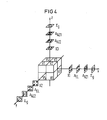
- the antenna axis x is determined by the intersection of the levels E1 and E2, the antenna axis y by the intersection between the levels E1 and E3 and the antenna axis z by the intersection between the levels E2 and E3.
- ⁇ represents a sum diagram with single lobe, ⁇ difference diagrams with double lobe and minimum valley and X diagonal difference diagrams with quadruple lobe and minimum cross.
- ⁇ g mean the total sum diagram , ⁇ E1 the elevation difference diagram , ⁇ Az1 and ⁇ Az2 the two azimuth difference diagrams and X1, X2 and X3 diagonal difference diagrams of the following form:
- X1 SV1 + SV2 + SV7 + SV8 - (SV3 + SV4 + SV5 + SV6)
- X2 SV1 + SV4 + SV6 + SV7 - (SV2 + SV3 + SV5 + SV8)
- X3 SV1 + SV5 + SV3 + SV7 - (SV2 + SV4 + SV6 + SV8)
- FIG. 5 shows a perspective view of a spherical, imaginary body 2, within the volume of which individual radiators 1 with omnidirectional characteristics are distributed.
- the distribution of the individual radiators 1 in volume is such that one is possible for all directions similar projected arrangement arises.
- the individual radiators 1 are designed for horizontal polarization and can be formed, for example, by conductor rings 7 lying horizontally or by crossed dipoles lying horizontally in the manner of turnstile antennas. Essentially perpendicular feed lines 3 lead to the individual radiators 1 from below.
- the individual radiators 1 accommodated in the imaginary sphere 2 are divided into eight octants V1 to V8 according to the cube combination according to FIG. Octant signals SV1 to SV8 are assigned to octants V1 to V8.
- the spatial separation of the feed lines 3 in their association with the individual octants V1 to V8 with a horizontal component in the extension of the supply lines takes place only outside the beam path of the group antenna, ie below the radiating "sphere" 2
- the outputs of these octant distributor plates P1 to P8 then supply the input signals SV1 to SV8 for the sum-difference circuit 4, which can be designed in accordance with the exemplary embodiments according to FIGS. 2 and 3.
- the sum-difference circuit 4 can be accommodated below the octant distributor plates P1 to P8 in parallel as a plate.
Landscapes
- Variable-Direction Aerials And Aerial Arrays (AREA)
Applications Claiming Priority (2)
| Application Number | Priority Date | Filing Date | Title |
|---|---|---|---|
| DE3524148 | 1985-07-05 | ||
| DE3524148 | 1985-07-05 |
Publications (3)
| Publication Number | Publication Date |
|---|---|
| EP0207511A2 true EP0207511A2 (fr) | 1987-01-07 |
| EP0207511A3 EP0207511A3 (en) | 1987-11-04 |
| EP0207511B1 EP0207511B1 (fr) | 1991-07-24 |
Family
ID=6275098
Family Applications (1)
| Application Number | Title | Priority Date | Filing Date |
|---|---|---|---|
| EP86109023A Expired - Lifetime EP0207511B1 (fr) | 1985-07-05 | 1986-07-02 | Antenne réseau à balayage électronique |
Country Status (3)
| Country | Link |
|---|---|
| US (1) | US4734700A (fr) |
| EP (1) | EP0207511B1 (fr) |
| DE (1) | DE3680396D1 (fr) |
Cited By (4)
| Publication number | Priority date | Publication date | Assignee | Title |
|---|---|---|---|---|
| EP0374008A1 (fr) * | 1988-12-16 | 1990-06-20 | Thomson-Csf | Antenne à couverture tridimensionnelle et balayage électronique, du type réseau volumique raréfié aléatoire |
| DE4002522A1 (de) * | 1990-01-29 | 1991-08-01 | Siemens Ag | Summen-differenz-anordnung fuer eine gruppenantenne |
| US5625160A (en) * | 1995-02-18 | 1997-04-29 | Diehl Gmbh & Co. | Protection arrangement for affording protection from an approaching projectile |
| US6175330B1 (en) * | 1998-11-26 | 2001-01-16 | Hollandse Signaalapparaten B.V. | Array antenna and method for operating an array antenna |
Families Citing this family (7)
| Publication number | Priority date | Publication date | Assignee | Title |
|---|---|---|---|---|
| US4882587A (en) * | 1987-04-29 | 1989-11-21 | Hughes Aircraft Company | Electronically roll stabilized and reconfigurable active array system |
| US5302961A (en) * | 1992-12-28 | 1994-04-12 | General Electric Co. | Antenna aperture with mainlobe jammer nulling capability |
| US5506589A (en) * | 1993-04-09 | 1996-04-09 | Hughes Aircraft Company | Monopulse array system with air-stripline multi-port network |
| US5717405A (en) * | 1996-07-17 | 1998-02-10 | Hughes Electronics | Four-port phase and amplitude equalizer for feed enhancement of wideband antenna arrays with low sum and difference sidelobes |
| US6011512A (en) * | 1998-02-25 | 2000-01-04 | Space Systems/Loral, Inc. | Thinned multiple beam phased array antenna |
| NL1011421C2 (nl) * | 1999-03-02 | 2000-09-05 | Tno | Volumetrisch phased array antenne systeem. |
| KR100902559B1 (ko) * | 2008-10-30 | 2009-06-11 | 국방과학연구소 | 레이더 간섭계 및 그것을 이용한 표적위치 추정방법 |
Family Cites Families (10)
| Publication number | Priority date | Publication date | Assignee | Title |
|---|---|---|---|---|
| US4023172A (en) * | 1959-12-17 | 1977-05-10 | Numax Electronics Incorporated | Monopulse system for cancellation of side lobe effects |
| US3243804A (en) * | 1963-07-26 | 1966-03-29 | Jr Ira D Smith | Four horn sequential lobing radar |
| US3344424A (en) * | 1965-12-30 | 1967-09-26 | Philip S Hacker | Control circuitry for multimode radar |
| US3471857A (en) * | 1967-05-24 | 1969-10-07 | Singer General Precision | Planar array antenna arrangements |
| DE2055981C3 (de) * | 1970-11-13 | 1974-02-14 | Siemens Ag, 1000 Berlin U. 8000 Muenchen | Schaltung für ein räumliches Monopulsradarsystem mit Sekundärradar-Abfrage |
| US3860924A (en) * | 1973-08-31 | 1975-01-14 | Hughes Aircraft Co | Moving target indicator system |
| US3946395A (en) * | 1974-04-17 | 1976-03-23 | Kirchhoff C Edward | Radio direction finding apparatus |
| DE2822845C2 (de) * | 1978-05-24 | 1983-12-01 | Siemens AG, 1000 Berlin und 8000 München | Gruppenantenne mit elektronisch gesteuerter Strahlschwenkung |
| US4316192A (en) * | 1979-11-01 | 1982-02-16 | The Bendix Corporation | Beam forming network for butler matrix fed circular array |
| FR2541518A1 (fr) * | 1982-10-26 | 1984-08-24 | Thomson Csf | Dispositif d'alimentation d'une antenne reseau a faisceau de balayage |
-
1986
- 1986-07-02 EP EP86109023A patent/EP0207511B1/fr not_active Expired - Lifetime
- 1986-07-02 DE DE8686109023T patent/DE3680396D1/de not_active Expired - Lifetime
- 1986-07-03 US US06/881,605 patent/US4734700A/en not_active Expired - Fee Related
Cited By (6)
| Publication number | Priority date | Publication date | Assignee | Title |
|---|---|---|---|---|
| EP0374008A1 (fr) * | 1988-12-16 | 1990-06-20 | Thomson-Csf | Antenne à couverture tridimensionnelle et balayage électronique, du type réseau volumique raréfié aléatoire |
| FR2640821A1 (fr) * | 1988-12-16 | 1990-06-22 | Thomson Csf | Antenne a couverture tridimensionnelle et balayage electronique, du type reseau volumique rarefie aleatoire |
| US5038149A (en) * | 1988-12-16 | 1991-08-06 | Thomson-Csf | Antenna with three-dimensional coverage and electronic scanning, of the random spare volume array type |
| DE4002522A1 (de) * | 1990-01-29 | 1991-08-01 | Siemens Ag | Summen-differenz-anordnung fuer eine gruppenantenne |
| US5625160A (en) * | 1995-02-18 | 1997-04-29 | Diehl Gmbh & Co. | Protection arrangement for affording protection from an approaching projectile |
| US6175330B1 (en) * | 1998-11-26 | 2001-01-16 | Hollandse Signaalapparaten B.V. | Array antenna and method for operating an array antenna |
Also Published As
| Publication number | Publication date |
|---|---|
| EP0207511A3 (en) | 1987-11-04 |
| US4734700A (en) | 1988-03-29 |
| EP0207511B1 (fr) | 1991-07-24 |
| DE3680396D1 (de) | 1991-08-29 |
Similar Documents
| Publication | Publication Date | Title |
|---|---|---|
| DE68907575T2 (de) | Den vollen Raumwinkel abtastende elektronische Antenne mit räumlich zufällig verteilten, verdünnt angeordneten Strahlern. | |
| DE69216998T2 (de) | Breitbandige konforme Gruppenantenne aus geneigten Schlitzleitungen | |
| DE3885871T2 (de) | Elektronisch steuerbare Antenne. | |
| DE69126941T2 (de) | Breitbandige, dualpolarizierte Mehrmodenantenne | |
| DE60000238T2 (de) | Phasengesteuerte Gruppenantenne mit aktiven Randelementen | |
| DE69934824T2 (de) | Sehr kompakte und breitbandige planare logperiodische dipol-gruppenantenne | |
| EP2735055B1 (fr) | Antenne à réflecteur pour un radar à ouverture synthétique | |
| EP0207511B1 (fr) | Antenne réseau à balayage électronique | |
| DE2638539A1 (de) | Doppelfrequenz-mikrostreifenantenne | |
| DE4026432A1 (de) | Planarantenne | |
| DE3042456C2 (fr) | ||
| EP1530816A1 (fr) | Dispositif de calibrage pour un reseau d'antennes commutable et procede pour faire fonctionner ce dispositif | |
| DE2744192A1 (de) | Antennenanordnung | |
| DE2802585A1 (de) | Antenne | |
| DE69224033T2 (de) | Antennensystem für Satelliten-Kommunikation | |
| DE2139216C3 (de) | Richtantennenanordnung, bestehend aus einem Hauptreflektorspiegel und zwei Primärstrahlersystemen und Verfahren zur Herstellung einer dielektrischen Reflektorplatte | |
| DE3839945A1 (de) | Phasengesteuerte gruppenantenne | |
| DE3840451C2 (de) | Linsenantenne | |
| DE69121970T2 (de) | Flugzeugantenne mit Korrektur von Fehlern, verursacht durch die konische Form des Antennenstrahls und durch Flugzeugschräglage | |
| EP0021193B1 (fr) | Système d'antennes combiné | |
| DE3885082T2 (de) | Phasengesteuerte Antenne mit Kopplern, die zu einem örtlich koppelndem Filter angordnet sind. | |
| DE2921856A1 (de) | Richtantenne | |
| DE2732627A1 (de) | Kreisfoermige phasengesteuerte strahlergruppe | |
| DE102012109106A1 (de) | Planarantenne mit verschachtelter Anordnung von Sendearray und Empfangsarray | |
| EP3333971B1 (fr) | Module de diffuseur dipolaire |
Legal Events
| Date | Code | Title | Description |
|---|---|---|---|
| PUAI | Public reference made under article 153(3) epc to a published international application that has entered the european phase |
Free format text: ORIGINAL CODE: 0009012 |
|
| AK | Designated contracting states |
Kind code of ref document: A2 Designated state(s): BE DE FR GB IT NL SE |
|
| PUAL | Search report despatched |
Free format text: ORIGINAL CODE: 0009013 |
|
| AK | Designated contracting states |
Kind code of ref document: A3 Designated state(s): BE DE FR GB IT NL SE |
|
| 17P | Request for examination filed |
Effective date: 19880425 |
|
| 17Q | First examination report despatched |
Effective date: 19900911 |
|
| GRAA | (expected) grant |
Free format text: ORIGINAL CODE: 0009210 |
|
| AK | Designated contracting states |
Kind code of ref document: B1 Designated state(s): BE DE FR GB IT NL SE |
|
| REF | Corresponds to: |
Ref document number: 3680396 Country of ref document: DE Date of ref document: 19910829 |
|
| ET | Fr: translation filed | ||
| ITF | It: translation for a ep patent filed | ||
| GBT | Gb: translation of ep patent filed (gb section 77(6)(a)/1977) | ||
| PGFP | Annual fee paid to national office [announced via postgrant information from national office to epo] |
Ref country code: GB Payment date: 19920519 Year of fee payment: 7 |
|
| PLBE | No opposition filed within time limit |
Free format text: ORIGINAL CODE: 0009261 |
|
| STAA | Information on the status of an ep patent application or granted ep patent |
Free format text: STATUS: NO OPPOSITION FILED WITHIN TIME LIMIT |
|
| 26N | No opposition filed | ||
| PGFP | Annual fee paid to national office [announced via postgrant information from national office to epo] |
Ref country code: BE Payment date: 19920717 Year of fee payment: 7 |
|
| PGFP | Annual fee paid to national office [announced via postgrant information from national office to epo] |
Ref country code: FR Payment date: 19920724 Year of fee payment: 7 |
|
| PGFP | Annual fee paid to national office [announced via postgrant information from national office to epo] |
Ref country code: SE Payment date: 19920728 Year of fee payment: 7 |
|
| PGFP | Annual fee paid to national office [announced via postgrant information from national office to epo] |
Ref country code: NL Payment date: 19920731 Year of fee payment: 7 |
|
| PG25 | Lapsed in a contracting state [announced via postgrant information from national office to epo] |
Ref country code: GB Effective date: 19930702 |
|
| PG25 | Lapsed in a contracting state [announced via postgrant information from national office to epo] |
Ref country code: SE Effective date: 19930703 |
|
| PG25 | Lapsed in a contracting state [announced via postgrant information from national office to epo] |
Ref country code: BE Effective date: 19930731 |
|
| BERE | Be: lapsed |
Owner name: SIEMENS A.G. Effective date: 19930731 |
|
| PG25 | Lapsed in a contracting state [announced via postgrant information from national office to epo] |
Ref country code: NL Effective date: 19940201 |
|
| GBPC | Gb: european patent ceased through non-payment of renewal fee |
Effective date: 19930702 |
|
| NLV4 | Nl: lapsed or anulled due to non-payment of the annual fee | ||
| PG25 | Lapsed in a contracting state [announced via postgrant information from national office to epo] |
Ref country code: FR Effective date: 19940331 |
|
| REG | Reference to a national code |
Ref country code: FR Ref legal event code: ST |
|
| EUG | Se: european patent has lapsed |
Ref document number: 86109023.1 Effective date: 19940210 |
|
| PGFP | Annual fee paid to national office [announced via postgrant information from national office to epo] |
Ref country code: DE Payment date: 20020711 Year of fee payment: 17 |
|
| PG25 | Lapsed in a contracting state [announced via postgrant information from national office to epo] |
Ref country code: DE Free format text: LAPSE BECAUSE OF NON-PAYMENT OF DUE FEES Effective date: 20040203 |
|
| PG25 | Lapsed in a contracting state [announced via postgrant information from national office to epo] |
Ref country code: IT Free format text: LAPSE BECAUSE OF NON-PAYMENT OF DUE FEES;WARNING: LAPSES OF ITALIAN PATENTS WITH EFFECTIVE DATE BEFORE 2007 MAY HAVE OCCURRED AT ANY TIME BEFORE 2007. THE CORRECT EFFECTIVE DATE MAY BE DIFFERENT FROM THE ONE RECORDED. Effective date: 20050702 |