EP0207576B1 - Dispositif pour déterminer la position et pour mesurer la profondeur d'un objet souterrain - Google Patents
Dispositif pour déterminer la position et pour mesurer la profondeur d'un objet souterrain Download PDFInfo
- Publication number
- EP0207576B1 EP0207576B1 EP19860201169 EP86201169A EP0207576B1 EP 0207576 B1 EP0207576 B1 EP 0207576B1 EP 19860201169 EP19860201169 EP 19860201169 EP 86201169 A EP86201169 A EP 86201169A EP 0207576 B1 EP0207576 B1 EP 0207576B1
- Authority
- EP
- European Patent Office
- Prior art keywords
- probe
- ground
- measuring
- anyone
- probe according
- Prior art date
- Legal status (The legal status is an assumption and is not a legal conclusion. Google has not performed a legal analysis and makes no representation as to the accuracy of the status listed.)
- Expired
Links
- 238000010276 construction Methods 0.000 title claims description 7
- 239000000523 sample Substances 0.000 claims description 58
- 230000002093 peripheral effect Effects 0.000 claims description 3
- 239000000463 material Substances 0.000 description 5
- 238000005553 drilling Methods 0.000 description 2
- 238000005259 measurement Methods 0.000 description 2
- 239000004576 sand Substances 0.000 description 2
- 229910000831 Steel Inorganic materials 0.000 description 1
- 230000001133 acceleration Effects 0.000 description 1
- 239000004927 clay Substances 0.000 description 1
- 230000000694 effects Effects 0.000 description 1
- 238000005243 fluidization Methods 0.000 description 1
- 210000003205 muscle Anatomy 0.000 description 1
- 230000035515 penetration Effects 0.000 description 1
- 239000002689 soil Substances 0.000 description 1
- 239000010959 steel Substances 0.000 description 1
- 229920003002 synthetic resin Polymers 0.000 description 1
- 239000000057 synthetic resin Substances 0.000 description 1
- 230000036346 tooth eruption Effects 0.000 description 1
- XLYOFNOQVPJJNP-UHFFFAOYSA-N water Substances O XLYOFNOQVPJJNP-UHFFFAOYSA-N 0.000 description 1
Images

Classifications
-
- E—FIXED CONSTRUCTIONS
- E21—EARTH OR ROCK DRILLING; MINING
- E21B—EARTH OR ROCK DRILLING; OBTAINING OIL, GAS, WATER, SOLUBLE OR MELTABLE MATERIALS OR A SLURRY OF MINERALS FROM WELLS
- E21B47/00—Survey of boreholes or wells
- E21B47/02—Determining slope or direction
-
- E—FIXED CONSTRUCTIONS
- E21—EARTH OR ROCK DRILLING; MINING
- E21B—EARTH OR ROCK DRILLING; OBTAINING OIL, GAS, WATER, SOLUBLE OR MELTABLE MATERIALS OR A SLURRY OF MINERALS FROM WELLS
- E21B47/00—Survey of boreholes or wells
- E21B47/04—Measuring depth or liquid level
-
- E—FIXED CONSTRUCTIONS
- E21—EARTH OR ROCK DRILLING; MINING
- E21B—EARTH OR ROCK DRILLING; OBTAINING OIL, GAS, WATER, SOLUBLE OR MELTABLE MATERIALS OR A SLURRY OF MINERALS FROM WELLS
- E21B7/00—Special methods or apparatus for drilling
- E21B7/18—Drilling by liquid or gas jets, with or without entrained pellets
-
- G—PHYSICS
- G01—MEASURING; TESTING
- G01B—MEASURING LENGTH, THICKNESS OR SIMILAR LINEAR DIMENSIONS; MEASURING ANGLES; MEASURING AREAS; MEASURING IRREGULARITIES OF SURFACES OR CONTOURS
- G01B13/00—Measuring arrangements characterised by the use of fluids
- G01B13/14—Measuring arrangements characterised by the use of fluids for measuring depth
-
- G—PHYSICS
- G01—MEASURING; TESTING
- G01B—MEASURING LENGTH, THICKNESS OR SIMILAR LINEAR DIMENSIONS; MEASURING ANGLES; MEASURING AREAS; MEASURING IRREGULARITIES OF SURFACES OR CONTOURS
- G01B5/00—Measuring arrangements characterised by the use of mechanical techniques
- G01B5/18—Measuring arrangements characterised by the use of mechanical techniques for measuring depth
Definitions
- the invention relates to a probe for determining the position and measuring the depth, on which a cable, conduit or other construction or object is positioned in the ground, said probe being hollow and elongate like a tube or pipe, the one end of said probe to be connected with a source of medium under pressure, said probe being provided with measuring means connected thereto and suitable for measuring the distance, over which the other end of said probe is brought into the ground.
- Such a probe is known from US-A-4 433 737.
- This prior art specification discloses a probe comprising a pipe-like operative lower end and means suitable for measuring the distance, over which that end of the probe is brought into the ground.
- the probe according to the invention is characterized by an external enlargement forming an integral part of the probe wall at said other end.
- This feature according to the invention has the effect that the ground material to be transported away is removed more easily, whilst furthermore the removing of the probe, if necessary after de-energizing of the source of medium under pressure, can take place very easily.
- NL-A-7 302 241 discloses a drilling tool provided with a tubular member carrying an outer ring arranged with a free space relative to the pipe outer wall.
- the pipe as well as the ring are provided with cutting teeth serving the purpose of cutting through the soil by rotatably driving the tool.
- the ring cuts into the ground loosening a cylindrical ground portion, which is subsequently blown away by the gas under pressure supplied through the tube.
- This construction does not ensure a ready removal of the probe after its penetration in the ground.
- the user will have to apply a considerable effort to penetrate into the ground.
- the enlargement may be generally spherically shaped.
- adjusting means for adjusting the medium flow In order to have the fluidization of the ground material to be removed to take place as effectively as possible while using as small as possible a quantity of medium preferably use is made of adjusting means for adjusting the medium flow.
- measuring means are designed as a scale on the outer surface of said probe.
- the measuring means comprise a pressure sensor arranged at said other end of the probe.
- the sensor measures the pressure of the medium at the outflow end of the probe. This pressure is, in connection with the ground condition, representative of the depth reached.
- the probe may during operation by the user lightly be moved up and down and guided.
- the up and down movement is particularly important in case of harder sand layers; in case of somewhat softer sand layers this up and down movement is not necessary.
- the probe may be designed as a tube made of high-quality steel, the inner diameter and the outer diameter of which can be chosen in dependence upon its length.
- the probe according to the invention is accordingly very suitable for localizing synthetic resin conduits, that are readily damaged with e.g. the drilling tool disclosed in NL-A-7 302 241 discussed above.
- the probe according to the invention allows a quick measurement or a large number of measurements within a given time interval.
- Figure 1 is a schematic representation of a first embodiment of a probe, which is shown in longitudinal section;
- figure 2 is a perspective view of a probe in a different embodiment
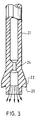
- figure 3 is a longitudinal section of a detail, namely the lower or foremost end of an alternative embodiment.
- Figure 1 shows in longitudinal section a hollow elongate probe 2 brought partly into the ground 1, the upper end 3 of the probe 2 remaining overground being connected through a conduit 5 provided with a control valve 4, with a pressure-air cylinder 6, which in an alternative embodiment may be replaced by a compressor.
- Probe 2 is provided, at its lower end 7, that has to be brought into the ground, with an internal constriction 8 and an external enlargement 9.
- the lower end is provided with a pressure senor 10, tht is, through a conduit 11, connected with a measuring apparatus 12 that determines the relation between the pressure measured by sensor 10 and the depth, on which the sensor 10 is positioned.
- Arrows 13 indicate the undisturbed medium flow in probe 2.
- Arrows 14 refer to the constricting medium flow at the constricting end, and at last arrows 15 indicate the way, in which the medium after leaving the probe and conveying ground material is drained off through the space 16 having the shape of a cylinder surface, the diameter of which approximatily corresponds to or is a little larger than the diameter of the enlargement 9.
- the annular raised zone on the ground is referred to with reference 17.
- Probe 2 can be pushed into the ground with a very small force. As soon as the user feels that the lower end of probe 2 touches e.g. a conduit 18, he reads, on measuring apparatus 12, the depth, on which the end of the probe is positioned underground.
- Figure 2 shows a measuring probe 19 of a simpler type, the shape of which corresponds with probe 2 according to figure 1, which, however, is not provided with the pressure sensor 10 and conduit 11 for determining the depth, but the outer surface of which is provided with a scale 20, by means of which the user can read directly the depth, on which the lower end of probe 9 is positioned at the moment, on which it touched a construction or a object.
- Figure 3 shows a probe 21 provided with an enlargement 22 at its foremost end, which is provided with a cutting edge 23 at its peripheral edge directed to said foremost end.
- a ring 24 is present causing a constriction of the passage. This constriction is positioned a little rearwardly relative to the foremost end.
- This embodiment is particularly intended for position-determination and measuring in clay-ground.
Landscapes
- Physics & Mathematics (AREA)
- Geology (AREA)
- Life Sciences & Earth Sciences (AREA)
- Engineering & Computer Science (AREA)
- Mining & Mineral Resources (AREA)
- Environmental & Geological Engineering (AREA)
- Fluid Mechanics (AREA)
- General Life Sciences & Earth Sciences (AREA)
- Geochemistry & Mineralogy (AREA)
- Geophysics (AREA)
- General Physics & Mathematics (AREA)
- Measuring Fluid Pressure (AREA)
- A Measuring Device Byusing Mechanical Method (AREA)
- Geophysics And Detection Of Objects (AREA)
Claims (8)
- Sonde (2) pour déterminer la position et mesurer la profondeur à laquelle un câble, une canalisation (18) ou autre construction ou objet est placé dans le sol (1), ladite sonde (2) étant creuse et allongée comme Un tube ou un tuyau, une extrémité (3) de ladite sonde (2) étant raccordée à une source (6) d'un milieu sous pression, ladite sonde étant munie de moyens de mesure (20) qui lui sont connectés et qui sont adaptés pour mesurer la distance, à laquelle l'autre extrémité (7) de ladite sonde (2) est amenée dans le sol (1), caractérisée par un renflement externe (9) faisant partie intégrante de la paroi de la sonde (2) à ladite autre extrémité (7).
- Sonde selon la revendication 1, caractérisée en ce que ledit renflement (9) a une forme générale sphérique.
- Sonde selon la revendication 1, caractérisée en ce que ledit renflement (22) est muni d'une arête coupante (23) sur son bord périphérique dirigé vers ladite autre extrémité (7).
- Sonde selon l'une quelconque des revendication précédentes, caractérisée en ce que la sonde (2) est raccordée à une source (6) d'air sous pression.
- Sonde selon l'une quelconque des revendications précédentes, caractérisée par des moyens de réglage (4) pour régler le débit du milieu.
- Sonde selon l'une quelconque des revendications précédentes, caractérisée en ce que lesdits moyens de mesure sont sous forme d'une graduation (20) sur la surface extérieure de ladite sonde (2).
- Sonde selon l'une quelconque des revendications précédentes, caractérisée en ce que lesdits moyens de mesure comprennent un détecteur de pression (10) agencé à ladite autre extrémité (7).
- Sonde selon l'une quelconque des revendications précédentes, caractérisée en ce que ladite sonde présente un rétrécissement intérieur (8) à ladite autre extrémité (7).
Applications Claiming Priority (2)
| Application Number | Priority Date | Filing Date | Title |
|---|---|---|---|
| NL8501930A NL8501930A (nl) | 1985-07-05 | 1985-07-05 | Inrichting voor het bepalen van de plaats en meten van de diepte waarop een constructie of voorwerp zich in de grond bevindt. |
| NL8501930 | 1985-07-05 |
Publications (2)
| Publication Number | Publication Date |
|---|---|
| EP0207576A1 EP0207576A1 (fr) | 1987-01-07 |
| EP0207576B1 true EP0207576B1 (fr) | 1991-04-03 |
Family
ID=19846252
Family Applications (1)
| Application Number | Title | Priority Date | Filing Date |
|---|---|---|---|
| EP19860201169 Expired EP0207576B1 (fr) | 1985-07-05 | 1986-07-02 | Dispositif pour déterminer la position et pour mesurer la profondeur d'un objet souterrain |
Country Status (3)
| Country | Link |
|---|---|
| EP (1) | EP0207576B1 (fr) |
| DE (1) | DE3678500D1 (fr) |
| NL (1) | NL8501930A (fr) |
Families Citing this family (4)
| Publication number | Priority date | Publication date | Assignee | Title |
|---|---|---|---|---|
| CN103727864A (zh) * | 2014-01-03 | 2014-04-16 | 华国洋 | 一种测土壤深度的钻杆 |
| CN104089566B (zh) * | 2014-07-18 | 2017-01-11 | 国家电网公司 | 接地排埋深探测器 |
| CN106468532B (zh) * | 2016-10-11 | 2019-02-15 | 浙江超威创元实业有限公司 | 一种铝塑膜冲坑深度测量设备及其测量方法 |
| CN108931176A (zh) * | 2018-07-27 | 2018-12-04 | 潘锐 | 一种高精度深度检测设备 |
Family Cites Families (5)
| Publication number | Priority date | Publication date | Assignee | Title |
|---|---|---|---|---|
| GB1279399A (en) * | 1968-12-03 | 1972-06-28 | British Petroleum Co | Nozzle |
| US3690166A (en) * | 1969-05-09 | 1972-09-12 | C Fitzhugh Grice | Apparatus for measuring subsurface soil characteristics |
| NL7302241A (fr) * | 1973-02-16 | 1974-08-20 | ||
| US3938600A (en) * | 1973-07-16 | 1976-02-17 | Continental Oil Company | Hydraulic mining nozzle-air lift device |
| US4433737A (en) * | 1982-03-25 | 1984-02-28 | The United States Of America As Represented By The Secretary Of The Navy | Water jet sediment probe |
-
1985
- 1985-07-05 NL NL8501930A patent/NL8501930A/nl not_active Application Discontinuation
-
1986
- 1986-07-02 EP EP19860201169 patent/EP0207576B1/fr not_active Expired
- 1986-07-02 DE DE8686201169T patent/DE3678500D1/de not_active Expired - Fee Related
Also Published As
| Publication number | Publication date |
|---|---|
| EP0207576A1 (fr) | 1987-01-07 |
| NL8501930A (nl) | 1987-02-02 |
| DE3678500D1 (de) | 1991-05-08 |
Similar Documents
| Publication | Publication Date | Title |
|---|---|---|
| JP2708067B2 (ja) | 自動推進式衝撃掘削機 | |
| EP0357314A3 (fr) | Dispositif pour contrôler la position d'un outil de forage autopropulsé | |
| US4890483A (en) | Apparatus for testing the watertight capacity of pipes | |
| DE559592T1 (de) | Vorrichtung zur In-situ-Sanierung von nichtbegehbaren Rohrleitungen oder Kanälen und Verfahren zur Wiederherstellung mit Hilfe einer solchen. | |
| US6637523B2 (en) | Drilling process monitor | |
| CA1167434A (fr) | Methode et dispositif de positionnement du porte- chariot d'un outil de foration a l'ecartement voulu d'une face d'attaque | |
| CA1284459C (fr) | Outil coupe-tube par l'interieur du tube | |
| GB1406769A (en) | Pneumatic burrowing apparatus | |
| EP0980739A3 (fr) | Rectifieuse | |
| US6016878A (en) | Method and device for drilling | |
| EP0207576A1 (fr) | Dispositif pour déterminer la position et pour mesurer la profondeur d'un objet souterrain | |
| EP0076283A1 (fr) | Ameliorations se rapportant au revetement interieur d'egouts, tuyaux, ou autres. | |
| US4447778A (en) | Apparatus for securing storage tape on a test piece during magnetographic testing | |
| GB1422693A (en) | Method and apparatus for boring a pit in earth | |
| US6070452A (en) | Pipe leak locator with pressure gauge | |
| AU751071B2 (en) | Rock drilling device | |
| CN209910782U (zh) | 深孔地下水位监测装置 | |
| CA1182283A (fr) | Outil ebarbeur | |
| CN209655041U (zh) | 一种基于示踪探头的大口径管道探测装置 | |
| CN109131757B (zh) | 野外流体平面作业远程操控工作台 | |
| EP0886129A3 (fr) | Procédé et moyens pour la détection du niveau d' un liquide | |
| JPS5542022A (en) | Remote drive system for supersonic probe | |
| CN218330684U (zh) | 一种土壤墒情测定用采样装置 | |
| CN221078653U (zh) | 一种土壤水分检测装置 | |
| SU907171A1 (ru) | Стенд дл исследовани процесса бестраншейной прокладки |
Legal Events
| Date | Code | Title | Description |
|---|---|---|---|
| PUAI | Public reference made under article 153(3) epc to a published international application that has entered the european phase |
Free format text: ORIGINAL CODE: 0009012 |
|
| AK | Designated contracting states |
Kind code of ref document: A1 Designated state(s): BE DE GB NL |
|
| 17P | Request for examination filed |
Effective date: 19870707 |
|
| 17Q | First examination report despatched |
Effective date: 19890616 |
|
| GRAA | (expected) grant |
Free format text: ORIGINAL CODE: 0009210 |
|
| AK | Designated contracting states |
Kind code of ref document: B1 Designated state(s): BE DE GB NL |
|
| PG25 | Lapsed in a contracting state [announced via postgrant information from national office to epo] |
Ref country code: BE Effective date: 19910403 |
|
| REF | Corresponds to: |
Ref document number: 3678500 Country of ref document: DE Date of ref document: 19910508 |
|
| PG25 | Lapsed in a contracting state [announced via postgrant information from national office to epo] |
Ref country code: GB Effective date: 19910703 |
|
| PLBE | No opposition filed within time limit |
Free format text: ORIGINAL CODE: 0009261 |
|
| STAA | Information on the status of an ep patent application or granted ep patent |
Free format text: STATUS: NO OPPOSITION FILED WITHIN TIME LIMIT |
|
| GBPC | Gb: european patent ceased through non-payment of renewal fee | ||
| 26N | No opposition filed | ||
| PG25 | Lapsed in a contracting state [announced via postgrant information from national office to epo] |
Ref country code: DE Effective date: 19920401 |
|
| PGFP | Annual fee paid to national office [announced via postgrant information from national office to epo] |
Ref country code: NL Payment date: 19940731 Year of fee payment: 9 |
|
| PG25 | Lapsed in a contracting state [announced via postgrant information from national office to epo] |
Ref country code: NL Effective date: 19960201 |
|
| NLV4 | Nl: lapsed or anulled due to non-payment of the annual fee |
Effective date: 19960201 |