EP0207603A1 - Système de commande pour une transmission continue - Google Patents
Système de commande pour une transmission continue Download PDFInfo
- Publication number
- EP0207603A1 EP0207603A1 EP86303548A EP86303548A EP0207603A1 EP 0207603 A1 EP0207603 A1 EP 0207603A1 EP 86303548 A EP86303548 A EP 86303548A EP 86303548 A EP86303548 A EP 86303548A EP 0207603 A1 EP0207603 A1 EP 0207603A1
- Authority
- EP
- European Patent Office
- Prior art keywords
- transmission ratio
- control
- valve
- spool
- control valve
- Prior art date
- Legal status (The legal status is an assumption and is not a legal conclusion. Google has not performed a legal analysis and makes no representation as to the accuracy of the status listed.)
- Granted
Links
- 230000005540 biological transmission Effects 0.000 title claims abstract description 93
- 230000008859 change Effects 0.000 claims abstract description 5
- 230000001419 dependent effect Effects 0.000 claims description 7
- 238000002485 combustion reaction Methods 0.000 claims description 2
- 230000009467 reduction Effects 0.000 description 4
- 238000010276 construction Methods 0.000 description 3
- 230000001133 acceleration Effects 0.000 description 2
- 230000003247 decreasing effect Effects 0.000 description 2
- 238000010586 diagram Methods 0.000 description 2
- 230000005484 gravity Effects 0.000 description 2
- 230000007935 neutral effect Effects 0.000 description 2
- 230000004044 response Effects 0.000 description 2
- 230000007423 decrease Effects 0.000 description 1
- 230000000994 depressogenic effect Effects 0.000 description 1
- 239000012530 fluid Substances 0.000 description 1
- 230000007246 mechanism Effects 0.000 description 1
- 230000004048 modification Effects 0.000 description 1
- 238000012986 modification Methods 0.000 description 1
- 239000000843 powder Substances 0.000 description 1
- 230000010349 pulsation Effects 0.000 description 1
Images



Classifications
-
- B—PERFORMING OPERATIONS; TRANSPORTING
- B60—VEHICLES IN GENERAL
- B60W—CONJOINT CONTROL OF VEHICLE SUB-UNITS OF DIFFERENT TYPE OR DIFFERENT FUNCTION; CONTROL SYSTEMS SPECIALLY ADAPTED FOR HYBRID VEHICLES; ROAD VEHICLE DRIVE CONTROL SYSTEMS FOR PURPOSES NOT RELATED TO THE CONTROL OF A PARTICULAR SUB-UNIT
- B60W30/00—Purposes of road vehicle drive control systems not related to the control of a particular sub-unit, e.g. of systems using conjoint control of vehicle sub-units
- B60W30/18—Propelling the vehicle
-
- B—PERFORMING OPERATIONS; TRANSPORTING
- B60—VEHICLES IN GENERAL
- B60W—CONJOINT CONTROL OF VEHICLE SUB-UNITS OF DIFFERENT TYPE OR DIFFERENT FUNCTION; CONTROL SYSTEMS SPECIALLY ADAPTED FOR HYBRID VEHICLES; ROAD VEHICLE DRIVE CONTROL SYSTEMS FOR PURPOSES NOT RELATED TO THE CONTROL OF A PARTICULAR SUB-UNIT
- B60W10/00—Conjoint control of vehicle sub-units of different type or different function
- B60W10/04—Conjoint control of vehicle sub-units of different type or different function including control of propulsion units
-
- B—PERFORMING OPERATIONS; TRANSPORTING
- B60—VEHICLES IN GENERAL
- B60W—CONJOINT CONTROL OF VEHICLE SUB-UNITS OF DIFFERENT TYPE OR DIFFERENT FUNCTION; CONTROL SYSTEMS SPECIALLY ADAPTED FOR HYBRID VEHICLES; ROAD VEHICLE DRIVE CONTROL SYSTEMS FOR PURPOSES NOT RELATED TO THE CONTROL OF A PARTICULAR SUB-UNIT
- B60W10/00—Conjoint control of vehicle sub-units of different type or different function
- B60W10/10—Conjoint control of vehicle sub-units of different type or different function including control of change-speed gearings
- B60W10/101—Infinitely variable gearings
-
- B—PERFORMING OPERATIONS; TRANSPORTING
- B60—VEHICLES IN GENERAL
- B60W—CONJOINT CONTROL OF VEHICLE SUB-UNITS OF DIFFERENT TYPE OR DIFFERENT FUNCTION; CONTROL SYSTEMS SPECIALLY ADAPTED FOR HYBRID VEHICLES; ROAD VEHICLE DRIVE CONTROL SYSTEMS FOR PURPOSES NOT RELATED TO THE CONTROL OF A PARTICULAR SUB-UNIT
- B60W30/00—Purposes of road vehicle drive control systems not related to the control of a particular sub-unit, e.g. of systems using conjoint control of vehicle sub-units
- B60W30/18—Propelling the vehicle
- B60W30/1819—Propulsion control with control means using analogue circuits, relays or mechanical links
-
- F—MECHANICAL ENGINEERING; LIGHTING; HEATING; WEAPONS; BLASTING
- F16—ENGINEERING ELEMENTS AND UNITS; GENERAL MEASURES FOR PRODUCING AND MAINTAINING EFFECTIVE FUNCTIONING OF MACHINES OR INSTALLATIONS; THERMAL INSULATION IN GENERAL
- F16H—GEARING
- F16H61/00—Control functions within control units of change-speed- or reversing-gearings for conveying rotary motion ; Control of exclusively fluid gearing, friction gearing, gearings with endless flexible members or other particular types of gearing
- F16H61/66—Control functions within control units of change-speed- or reversing-gearings for conveying rotary motion ; Control of exclusively fluid gearing, friction gearing, gearings with endless flexible members or other particular types of gearing specially adapted for continuously variable gearings
-
- F—MECHANICAL ENGINEERING; LIGHTING; HEATING; WEAPONS; BLASTING
- F16—ENGINEERING ELEMENTS AND UNITS; GENERAL MEASURES FOR PRODUCING AND MAINTAINING EFFECTIVE FUNCTIONING OF MACHINES OR INSTALLATIONS; THERMAL INSULATION IN GENERAL
- F16H—GEARING
- F16H61/00—Control functions within control units of change-speed- or reversing-gearings for conveying rotary motion ; Control of exclusively fluid gearing, friction gearing, gearings with endless flexible members or other particular types of gearing
- F16H61/66—Control functions within control units of change-speed- or reversing-gearings for conveying rotary motion ; Control of exclusively fluid gearing, friction gearing, gearings with endless flexible members or other particular types of gearing specially adapted for continuously variable gearings
- F16H61/662—Control functions within control units of change-speed- or reversing-gearings for conveying rotary motion ; Control of exclusively fluid gearing, friction gearing, gearings with endless flexible members or other particular types of gearing specially adapted for continuously variable gearings with endless flexible members
- F16H61/66254—Control functions within control units of change-speed- or reversing-gearings for conveying rotary motion ; Control of exclusively fluid gearing, friction gearing, gearings with endless flexible members or other particular types of gearing specially adapted for continuously variable gearings with endless flexible members controlling of shifting being influenced by a signal derived from the engine and the main coupling
- F16H61/66259—Control functions within control units of change-speed- or reversing-gearings for conveying rotary motion ; Control of exclusively fluid gearing, friction gearing, gearings with endless flexible members or other particular types of gearing specially adapted for continuously variable gearings with endless flexible members controlling of shifting being influenced by a signal derived from the engine and the main coupling using electrical or electronical sensing or control means
Definitions
- the present invention relates to a control system for an infinitely variable belt-drive automatic transmission for a motor vehicle, and more particularly to a system for controlling the speed of changing the transmission ratio in accordance with driving conditions of the vehicle.
- a known control system for an infinitely variable belt-drive transmission disclosed in United States Patent No. 4,369,675 comprises an endless belt running over a drive pulley and a driven pulley.
- Each pulley comprises a movable conical disc which is axially moved by a fluid operated servo device so as to vary the running diameter of the belt on the pulleys in dependence on driving conditions.
- the system is provided with a line pressure control valve and a transmission ratio control valve.
- Each valve comprises a spool to control the oil supplied to the servo devices.
- the transmission ratio control valve operates to control the transmission ratio in accordance with the opening degree of a throttle valve of an engine and the speed of the engine.
- the line pressure control valve is adapted to control the line pressure in accordance with the transmission ratio and the engine speed.
- the output of the engine is transmitted to the drive pulley through a clutch.
- the line pressure is controlled to prevent the belt from slipping on pulleys in order to transmit the output of the engine.
- the transmission ratio On starting the vehicle, the transmission ratio is set at a maximum value. When the vehicle speed and engine speed reach set valves under a particular driving condition, the transmission ratio starts to change (to upshift). At that time if the engine speed is kept constant, the transmission ratio is automatically and continuously reduced at a speed which is decided by line pressure, pressure of oil supplied to the servo device of the drive pulley, and actual transmission ratio. In such a system, the speed of changing of transmission ratio up to a desired transmission ratio cannot be controlled in accordance with driving conditions. Accordingly, hunting or overshoot of transmission ratio occurs, which causes the driveability of the vehicle to deteriorate.
- Japenese Patent Laid Open 59-159456 discloses a system provided with a first valve for changing the direction of the transmission ratio change and a second valve for controlling the transmission ratio changing speeds. By controlling the spool of the second valve, the transmission ratio changing speed is controlled.
- Japanese Patent Laid Open 59-217048 shows a system which operates to vary a desired transmission ratio in accordance with the deviation of an actual transmission ratio from the desired ratio. However, such a system tends to cause overshoot of the control operation.
- the present invention seeks to provide a system which can control the transmission ratio changing speed by means of a single control valve.
- the present invention also seeks to provide a system which has a fast response thereby preventing overshoot of the control.
- the present invention provides a control system for an infinitely variable transmission for transmitting the power of an internal combustion engine, the system comprising a drive pulley and a driven pulley each having a hydraulically shiftable disc and a hydraulic cylinder for shifting the disc, a belt engaged with both pulleys, a first hydraulic circuit having a pump for supplying oil, and a spool valve for controlling the oil supplied to the cylinder of the drive pulley to change the transmission ratio, characterised by: a second hydraulic circuit for supplying oil to the transmission ratio control valve so as to shift the spool; control valve means provided in the second hydraulic circuit for controlling the amount of control oil supplied to the transmission ratio control valve; sensing means for sensing operation conditions of the engine and the transmission and for producing signals dependent on the operating conditions; first means responsive to the signals from the sensing means for producing an output signal representing the difference between a desired transmission ratio and an actual transmission ratio; and second means responsive to the output signal for producing an operating signal for operating the control valve means, so that the shifting of the spool of the system
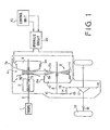
- the infinitely variable drive-belt automatic transmission for a motor vehicle to which the present invention is applied comprises an electromagnetic powder clutch 2 for transmitting the power of an engine 1 to transmission 4 through a selector mechanism 3.
- the belt-drive transmission has a main shaft 5 and an output shaft 6 mounted parallel to the main shaft 5.
- a drive pulley (primary pulley) 7 and a driven pulley (secondary pulley) 8 are mounted on shafts 5 and 6 respectively.
- a fixed conical disc 7b of the drive pulley 7 is integral with main shaft 5 and an axially movable conical disc 7a is axially slidably mounted on the main shaft 5.
- the movable conical disc 7a also slides in a cylinder 9a formed on the main shaft 5 to provide a servo device.
- a chamber 9 of the servo device communicates with a hydraulic circuit 20.
- a fixed conical disc 8b of the driven pulley 8 is formed on the output shaft 6 facing a movable conical disc 8a having a cylindrical portion which is slidably engaged in a cylinder 6a of the output shaft 6 to form a servo device.
- a chamber 10 of the servo device also communicates with hydraulic control circuit 20.
- a drive belt 11 engages with the drive pulley 7 and the driven pulley 8.
- a drive gear 12 Secured to the output shaft 6 is a drive gear 12 which engages with an intermediate reduction gear 13 on an intermediate shaft 14.
- An intermediate gear 15 on the shaft 14 engages with a final reduction gear16.
- the rotation of the final reduction gear 16 is transmitted to axles 18 of the vehicle driving wheels 19 through a differential 17.
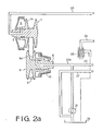
- chamber 9 of the drive pulley 7 is supplied with pressurised oil by an oil pump 21 from an oil reservoir 26 passing through a line pressure conduit 22, ports 41a and 41e of a line pressure control valve 40, transmission ratio control valve 50, and conduit 23.
- the chamber 10 of driven pulley 8 is supplied with pressurised oil through a passage 22b without passing through valves 40 and 50.
- the movable conical disc 7a of the drive pulley 7 is so designed that the pressure receiving area thereof is larger than that of movable conical disc 8a of the driven pulley 8.
- the line pressure control valve 40 comprises a valve body 41, spool 42, and chambers 41c and 41d.
- the spool 42 is pressurised by supply of the pressurised oil to the chamber 41c, via a conduit 31.
- the other end of the spool 42 is biassed by a spring 43 provided between the end of the spool and a retainer 45 the position of which is adjustable by a screw 44.
- the port 41a communicates with a port 41b of a drain passage 27 in accordance with the position of a land of the spool 42.
- the tranmission ratio control valve 50 comprises a valve body 51, spool 52 and spring 53 for urging the spool in the downshift direction.
- a port 51b of the valve body 51 is selectively communicated with a pressure oil supply port 51a or a drain port 51c in accordance with the position of lands of the spool 52.
- Port 51b communicates with chamber 9 through a conduit 23, and port 51a communicates with line pressure control valve 40 through conduit 22a.
- the drain port 51c is connected with the oil reservoir 26 through a conduit 24 and a check valve 25.
- the drain port 41b communicates with oil reservoir 26 through passage 27.
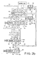
- the system of the present invention is provided with a regulator supply valve 55, regulator valve 60, solenoid operated on-off control valves 66 and 68.
- the regulator supply valve 55 comprises a valve body 56, spool 57, spring 58 for biassing the spool in one direction, port 56a connected to line pressure conduit 22 through passage 35, port 56c connected to drain passage 27 through a passage 36, and end chamber 56d which is communicated with drain passage 27 to be applied with the drain oil pressure opposite the spring 58.
- the line pressure is at a high level, the pressure of drain oil is at a low level because of closure of the port 41b of the line pressure control valve 40. In this condition, spool 57 is shifted to the right to communicate port 56a with an output port 56b.
- the regulator valve 60 comprises a valve body 61, spool 62, end chamber 61c, spring 63 urging the spool 62 to the chamber 61c.
- the spool 72 is shifted to the left, so that an inlet port 61a communicates with a drain port 61b to drain the oil.
- a constant pressure of oil is provided in the passage 37.
- the passage 37 is connected with the chamber 41d of line pressure control valve 40 through a constant pressure passage 38, orifice 65, solenoid operated on-off valve 66, and passage 32. Further, the passage 38 is communicated with an end chamber 51d of the transmission ratio control valve 50 through a passage 33, and with another end chamber 51e through a passage 34, orifice 67, and solenoid operated on-off valve 68.
- the solenoid operated valve 66 is adapted to be operated by pulses. When energized, a valve 66a opens a drain port 66b. The pulsation of the pressure of oil in the passage 32 is smoothed by orifice 65.
- the solenoid operated valve 68 is the same as valve 66 in construction and operation.
- the control valves 66 and 68 are operated by signals from a control unit 70. Thus, pressure controlled by the control valves 66 and 68 is applied to chambers 41d and 51e.
- the line pressure Pl is in inverse poroportion to the control pressure P d .
- pressure receiving area of the spool 52 at chamber 51e is set at a value larger than the area at the chamber 51d.
- the control pressure in the chamber 51e can be changed between a maximum value, which is the same as the constant pressure in the chamber 51d when the duty ratio is 0%, and zero by controlling the duty ratio of pulses for operating the control valve 68.
- the transmission ratio control valve 50 is so arranged that the spool 52 is at a neutral position at a middle duty ratio (for example 50%) and is located in an oil supply position by increasing the duty ratio from the middle duty ratio because of reduction of control pressure in the chamber 51e. Further, the speed of the movement of the spool increases with decreasing of the duty ratio.
- the spool 52 is shifted to an oil drain position by decreasing the duty ratio. It will be understood that when oil is supplied to the chamber 9, the transmission is upshifted.
- the required volume V of oil in the chamber 9 is a function of the transmission ratio i, that is to say: V - f(i)
- Q s a ⁇ S s (P1-P p )/2
- a c(2g / ⁇ )/2
- P p the pressure in chamber 9
- P1 the line pressure
- C the coefficient for flow rate
- g the acceleration of gravity
- ⁇ is the specific gravity of oil
- S s is the opening area of supply port 51a
- S d is the opening area of drain port 51c.
- the duty ratio is determined by the transmission ratio changing speed di/dt and the transmission ratio i.
- the duty ratio D can be obtained from the speed.
- the actual transmission ratio i is larger than the desired transmission ratio id (i>id)
- the value of di/dt is negative.
- the duty ratio D is increased to reduce the pressure in the chamber 51e so as to upshift the transmission.
- the downshift is performed in the reverse manner.
- the system is arranged to control the transmission ratio in accordance with the above described principle.
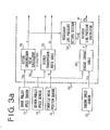
- a drive pulley speed sensor 71, driven pulley speed sensor 72, engine speed sensor 73 and throttle valve position sensor 74 are provided.
- the output signal N s of the sensor 72 and output signal ⁇ of the throttle valve position sensor 74 are fed to a desired transmission ratio table 76.
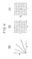
- Fig. 4a shows various actual transmission ratios i and Fig. 4b shows the table 76.
- the desired transmission ratio id is fetched from the table in accordance with the signals N s and ⁇ .
- the speed di/dt and actual ratio i are applied to a duty ratio table 79 to derive the duty ratio D.
- Fig. 4c shows the duty ratio table in which the duty ratio decreases with increases of speed di/dt and ratio i.
- the duty ratio D is supplied to the solenoid operated valve 68 through a driver 80.
- the output signal Ne of the engine speed sensor 73 and throttle position signal ⁇ are fed to an engine torque table 90 to derive engine torque T of Fig. 4d.
- the actual ratio i is applied to a required line pressure setting section 94 which produces a required line pressure PL u from a graph of Fig. 4e.
- the desired line pressure PL is applied to a duty ratio setting section 92 to produce a duty ratio DP dependent on the desired line pressure.
- Fig. 4f shows the duty ratio dependent on engine speed Ne and desired line pressure PL.
- the duty ratio DP is applied to the solenoid operated valve 66 through a driver 93.
- chamber 10 of the driven pulley is supplied with line pressure through conduit 22b, and the chamber 9 of the drive pulley is drained, since the N p , N s , ⁇ are zero and duty ratio is zero, so that the spool 52 is at the right hand end position and the drain port 51c communicates with the chamber 9 through the conduit 23 as shown in Figs. 2a and 2b.
- the driving belt 11 engages with the driven pulley 8 at a maximum running diameter to provide the largest transmission ratio (low speed stage).
- the electromagnetic clutch 2 is gradually engaged, transmitting the engine power to the drive pulley 7.
- the power of the engine is transmitted to the output shaft 6 at the largest transmission ratio by the driving belt 11 and driven pulley 8, and further transmitted to axles of the driving wheels 19.
- the vehicle is started.
- the line pressure is at the highest value by the pressure control valve 40, since the duty ratio for the valve 66 is large, and the spool 42 of the control valve 40 is at the right hand end position.
- the desired transmission ratio id and transmission ratio changing speed di/dt are calculated by calculators 76, 78, and duty ratio D is obtained from the table 79.
- the valve of the duty ratio D is larger than the neutral value, so that the pressure in the chamber 51d of the control valve 50 is higher than in the chamber 51e.
- the spool 52 is shifted to the left to communicate the port 51a with port 51b, so that oil is supplied to the chamber 9 through the conduit 23.
- the duty ratio of the control valve 66 is reduced, thereby shifting the spool 42 of the valve 40 to the left so that the port 41a communicates with the port 41b of the drain passage 27.
- line pressure reduces, and the transmission is upshifted, since oil is still supplied to the chamber 9 through the control valve 50.
- the duty ratio for the control valve 68 becomes large, thereby increasing the transmission changing speed di/dt.
- the opening degree of the throttle valve is reduced for deceleration, the duty ratio is reduced, thereby shifting the spool 52 to the right to drain the chamber 9.
- the transmission is downshifted.
- the transmission changing speed at downshifting increases with reducing of the duty ratio.
- the construction and operation of the system are simplified.
- the transmission ratio changing speed is decided by the difference between the desired transmission ratio and the actual transmission ratio. Accordingly, the response of the system can be improved.
Landscapes
- Engineering & Computer Science (AREA)
- Mechanical Engineering (AREA)
- Chemical & Material Sciences (AREA)
- Combustion & Propulsion (AREA)
- Transportation (AREA)
- General Engineering & Computer Science (AREA)
- Automation & Control Theory (AREA)
- Control Of Transmission Device (AREA)
- Control Of Driving Devices And Active Controlling Of Vehicle (AREA)
Applications Claiming Priority (2)
| Application Number | Priority Date | Filing Date | Title |
|---|---|---|---|
| JP60143472A JPS624647A (ja) | 1985-06-29 | 1985-06-29 | 無段変速機の制御装置 |
| JP143472/85 | 1985-06-29 |
Publications (2)
| Publication Number | Publication Date |
|---|---|
| EP0207603A1 true EP0207603A1 (fr) | 1987-01-07 |
| EP0207603B1 EP0207603B1 (fr) | 1990-05-16 |
Family
ID=15339491
Family Applications (1)
| Application Number | Title | Priority Date | Filing Date |
|---|---|---|---|
| EP86303548A Expired - Lifetime EP0207603B1 (fr) | 1985-06-29 | 1986-05-09 | Système de commande pour une transmission continue |
Country Status (4)
| Country | Link |
|---|---|
| US (1) | US4721019A (fr) |
| EP (1) | EP0207603B1 (fr) |
| JP (1) | JPS624647A (fr) |
| DE (1) | DE3671278D1 (fr) |
Cited By (9)
| Publication number | Priority date | Publication date | Assignee | Title |
|---|---|---|---|---|
| EP0257960A1 (fr) * | 1986-08-20 | 1988-03-02 | Fuji Jukogyo Kabushiki Kaisha | Système de commande pour un variateur continu de vitesse |
| EP0291272A1 (fr) * | 1987-05-12 | 1988-11-17 | Fuji Jukogyo Kabushiki Kaisha | Commande de la pression de l'huile dans un variateur continu de vitesse |
| EP0281944A3 (en) * | 1987-03-13 | 1989-07-19 | Borg-Warner Automotive, Inc. | Pulse width modulation technique |
| EP0364269A1 (fr) * | 1988-10-14 | 1990-04-18 | Fuji Jukogyo Kabushiki Kaisha | Système de commande du rapport de transmission pour un variateur continu de vitesse |
| US4942783A (en) * | 1986-08-23 | 1990-07-24 | Fuji Jukogyo Kabushiki Kaisha | Transmission ration control system for a continuously variable transmission |
| EP0330422A3 (en) * | 1988-02-22 | 1990-10-03 | Fuji Jukogyo Kabushiki Kaisha | Control system for a continuously variable transmission |
| WO1993000533A1 (fr) * | 1991-06-21 | 1993-01-07 | Dr. Ing. H.C. F. Porsche Aktiengesellschaft | Procede pour la commande d'une transmission a variation continue d'un vehicule automobile |
| EP0433929A3 (en) * | 1989-12-18 | 1993-04-07 | Mazda Motor Corporation | Speed shift control system of a continuous transmission |
| CN113738793A (zh) * | 2021-09-09 | 2021-12-03 | 北京裕峻汽车技术研究院有限公司 | 一种制动系统及液力缓速器的控制方法 |
Families Citing this family (3)
| Publication number | Priority date | Publication date | Assignee | Title |
|---|---|---|---|---|
| JP2529672B2 (ja) * | 1986-09-10 | 1996-08-28 | 日産自動車株式会社 | 無段変速機の変速制御装置 |
| JP3640477B2 (ja) * | 1996-10-11 | 2005-04-20 | 本田技研工業株式会社 | 無段変速機における油圧制御装置 |
| DE10164490A1 (de) * | 2001-12-29 | 2003-07-10 | Bosch Gmbh Robert | Steuerschaltung und Verfahren zur Erzeugung eines Steuersignals zur Steuerung eines stufenlos verstellbaren Umschlingungsgetriebes |
Citations (7)
| Publication number | Priority date | Publication date | Assignee | Title |
|---|---|---|---|---|
| US4369675A (en) * | 1978-11-13 | 1983-01-25 | Van Doorne's Transmissie B.V. | Method and apparatus for controlling an infinitely variable transmission of a motor vehicle |
| GB2133095A (en) * | 1983-01-06 | 1984-07-18 | Aisin Warner | Reduction ratio controlling mechanism for a continuously- variable automatic transmission of a vehicle |
| EP0117069A1 (fr) * | 1983-02-07 | 1984-08-29 | Toyota Jidosha Kabushiki Kaisha | Procédé de réglage d'une transmission à variation |
| EP0117696A1 (fr) * | 1983-02-26 | 1984-09-05 | Toyota Jidosha Kabushiki Kaisha | Dispositif hydraulique pour une transmission à variation continue |
| GB2138896A (en) * | 1983-04-29 | 1984-10-31 | Aisin Warner | An automatic transmission for a vehicle |
| GB2145785A (en) * | 1983-08-31 | 1985-04-03 | Fuji Heavy Ind Ltd | A system for controlling the transmission ratio of an infinitely variable belt-drive transmission |
| US4584907A (en) * | 1983-05-20 | 1986-04-29 | Toyota Jidosha Kabushiki Kaisha | Method for controlling a rate of changing an RPM ratio in a continuously variable transmission |
Family Cites Families (8)
| Publication number | Priority date | Publication date | Assignee | Title |
|---|---|---|---|---|
| FR2464853B1 (fr) * | 1979-09-12 | 1987-07-31 | Bosch Gmbh Robert | Installation de commande pour variateur de vitesse continu de vehicule automobile |
| JPS5790450A (en) * | 1980-11-27 | 1982-06-05 | Nippon Denso Co Ltd | Automatic change gear control apparatus for vehicle |
| US4458318A (en) * | 1981-04-24 | 1984-07-03 | Borg-Warner Corporation | Control arrangement for a variable pulley transmission |
| US4475416A (en) * | 1982-07-27 | 1984-10-09 | Borg-Warner Corporation | Continuously variable transmission down shift control |
| US4509125A (en) * | 1982-08-06 | 1985-04-02 | General Motors Corporation | Continuously variable transmission ratio control system |
| US4559850A (en) * | 1982-11-30 | 1985-12-24 | Aisin-Warner, Ltd. | Stepless automatic transmission for motor vehicles |
| US4534243A (en) * | 1983-04-26 | 1985-08-13 | Aisin Warner Kabushiki Kaisha | Hydraulic control system for a V-belt transmission |
| US4547178A (en) * | 1983-12-01 | 1985-10-15 | Fuji Medical Instruments Mfg. Co., Ltd. | Control system for an automatic transmission for a vehicle |
-
1985
- 1985-06-29 JP JP60143472A patent/JPS624647A/ja active Pending
-
1986
- 1986-04-04 US US06/848,060 patent/US4721019A/en not_active Expired - Fee Related
- 1986-05-09 DE DE8686303548T patent/DE3671278D1/de not_active Expired - Lifetime
- 1986-05-09 EP EP86303548A patent/EP0207603B1/fr not_active Expired - Lifetime
Patent Citations (7)
| Publication number | Priority date | Publication date | Assignee | Title |
|---|---|---|---|---|
| US4369675A (en) * | 1978-11-13 | 1983-01-25 | Van Doorne's Transmissie B.V. | Method and apparatus for controlling an infinitely variable transmission of a motor vehicle |
| GB2133095A (en) * | 1983-01-06 | 1984-07-18 | Aisin Warner | Reduction ratio controlling mechanism for a continuously- variable automatic transmission of a vehicle |
| EP0117069A1 (fr) * | 1983-02-07 | 1984-08-29 | Toyota Jidosha Kabushiki Kaisha | Procédé de réglage d'une transmission à variation |
| EP0117696A1 (fr) * | 1983-02-26 | 1984-09-05 | Toyota Jidosha Kabushiki Kaisha | Dispositif hydraulique pour une transmission à variation continue |
| GB2138896A (en) * | 1983-04-29 | 1984-10-31 | Aisin Warner | An automatic transmission for a vehicle |
| US4584907A (en) * | 1983-05-20 | 1986-04-29 | Toyota Jidosha Kabushiki Kaisha | Method for controlling a rate of changing an RPM ratio in a continuously variable transmission |
| GB2145785A (en) * | 1983-08-31 | 1985-04-03 | Fuji Heavy Ind Ltd | A system for controlling the transmission ratio of an infinitely variable belt-drive transmission |
Cited By (11)
| Publication number | Priority date | Publication date | Assignee | Title |
|---|---|---|---|---|
| EP0257960A1 (fr) * | 1986-08-20 | 1988-03-02 | Fuji Jukogyo Kabushiki Kaisha | Système de commande pour un variateur continu de vitesse |
| US4827803A (en) * | 1986-08-20 | 1989-05-09 | Fuji Jukogyo Kabushiki Kaisha | Transmission ratio control system for a continuously variable transmission |
| US4942783A (en) * | 1986-08-23 | 1990-07-24 | Fuji Jukogyo Kabushiki Kaisha | Transmission ration control system for a continuously variable transmission |
| EP0281944A3 (en) * | 1987-03-13 | 1989-07-19 | Borg-Warner Automotive, Inc. | Pulse width modulation technique |
| EP0291272A1 (fr) * | 1987-05-12 | 1988-11-17 | Fuji Jukogyo Kabushiki Kaisha | Commande de la pression de l'huile dans un variateur continu de vitesse |
| EP0330422A3 (en) * | 1988-02-22 | 1990-10-03 | Fuji Jukogyo Kabushiki Kaisha | Control system for a continuously variable transmission |
| EP0364269A1 (fr) * | 1988-10-14 | 1990-04-18 | Fuji Jukogyo Kabushiki Kaisha | Système de commande du rapport de transmission pour un variateur continu de vitesse |
| EP0433929A3 (en) * | 1989-12-18 | 1993-04-07 | Mazda Motor Corporation | Speed shift control system of a continuous transmission |
| WO1993000533A1 (fr) * | 1991-06-21 | 1993-01-07 | Dr. Ing. H.C. F. Porsche Aktiengesellschaft | Procede pour la commande d'une transmission a variation continue d'un vehicule automobile |
| US5527232A (en) * | 1991-06-21 | 1996-06-18 | Dr. Ing. H.C.F. Porsche Ag | Method for controlling a continuously variable transmission of a motor vehicle |
| CN113738793A (zh) * | 2021-09-09 | 2021-12-03 | 北京裕峻汽车技术研究院有限公司 | 一种制动系统及液力缓速器的控制方法 |
Also Published As
| Publication number | Publication date |
|---|---|
| JPS624647A (ja) | 1987-01-10 |
| EP0207603B1 (fr) | 1990-05-16 |
| US4721019A (en) | 1988-01-26 |
| DE3671278D1 (de) | 1990-06-21 |
Similar Documents
| Publication | Publication Date | Title |
|---|---|---|
| EP0207231B1 (fr) | Système de commande pour une transmission variable continûment | |
| US4674363A (en) | System for controlling the pressure of oil in a system for a continuously variable transmission | |
| EP0257960B1 (fr) | Système de commande pour un variateur continu de vitesse | |
| US4747325A (en) | Transmission ratio control system for a continuously variable transmission | |
| US4708031A (en) | Transmission ratio control system for a continuously variable transmission | |
| EP0214821A1 (fr) | Système pour régler la pression d'huile pour transmission continue | |
| US5020392A (en) | Transmission ratio control system for a continuously variable transmission | |
| EP0240282B1 (fr) | Système de commande de la pression de l'huile pour un variateur continu de vitesse | |
| EP0213948A1 (fr) | Système pour régler la pression d'huile pour une transmission continue | |
| EP0207227B1 (fr) | Système de commande pour transmission continue | |
| EP0233781B1 (fr) | Commande des rappos de changement de vitesse d'une transmission continue | |
| US4730518A (en) | System for the transmission ratio of a continuously variable transmission | |
| EP0207603B1 (fr) | Système de commande pour une transmission continue | |
| EP0258005B1 (fr) | Système de commande pour variateur continu de vitesse | |
| EP0260117A1 (fr) | Système de commande de rapport de transmission pour un variateur continu de vitesse | |
| US4751857A (en) | System for controlling the pressure of oil in a system for an infinitely variable transmission | |
| EP0207228B1 (fr) | Système de commande pour une transmission continue | |
| EP0257958A1 (fr) | Système de commande pour variateur continu de vitesse | |
| US4761153A (en) | Transmission ratio control system for a continuously variable transmission | |
| EP0291272A1 (fr) | Commande de la pression de l'huile dans un variateur continu de vitesse | |
| US4729264A (en) | System for controlling the pressure of oil in a system for a continuously variable transmission | |
| US4710151A (en) | System for controlling the pressure of oil in a system for a continuously variable transmission | |
| EP0228800A1 (fr) | Dispositif de pilotage de la pression du liquide dans une transmission continue de vitesse | |
| EP0240285A2 (fr) | Système de commande pour un variateur continu de vitesse | |
| US4708694A (en) | System for controlling the pressure of oil in a system for a continuously variable transmission |
Legal Events
| Date | Code | Title | Description |
|---|---|---|---|
| PUAI | Public reference made under article 153(3) epc to a published international application that has entered the european phase |
Free format text: ORIGINAL CODE: 0009012 |
|
| 17P | Request for examination filed |
Effective date: 19860516 |
|
| AK | Designated contracting states |
Kind code of ref document: A1 Designated state(s): CH DE FR GB IT LI NL |
|
| 17Q | First examination report despatched |
Effective date: 19880822 |
|
| GRAA | (expected) grant |
Free format text: ORIGINAL CODE: 0009210 |
|
| AK | Designated contracting states |
Kind code of ref document: B1 Designated state(s): CH DE FR GB IT LI NL |
|
| ET | Fr: translation filed | ||
| REF | Corresponds to: |
Ref document number: 3671278 Country of ref document: DE Date of ref document: 19900621 |
|
| ITF | It: translation for a ep patent filed | ||
| PLBE | No opposition filed within time limit |
Free format text: ORIGINAL CODE: 0009261 |
|
| STAA | Information on the status of an ep patent application or granted ep patent |
Free format text: STATUS: NO OPPOSITION FILED WITHIN TIME LIMIT |
|
| PGFP | Annual fee paid to national office [announced via postgrant information from national office to epo] |
Ref country code: FR Payment date: 19910415 Year of fee payment: 6 |
|
| PGFP | Annual fee paid to national office [announced via postgrant information from national office to epo] |
Ref country code: CH Payment date: 19910425 Year of fee payment: 6 |
|
| 26N | No opposition filed | ||
| PGFP | Annual fee paid to national office [announced via postgrant information from national office to epo] |
Ref country code: GB Payment date: 19910507 Year of fee payment: 6 |
|
| PGFP | Annual fee paid to national office [announced via postgrant information from national office to epo] |
Ref country code: DE Payment date: 19910527 Year of fee payment: 6 |
|
| ITTA | It: last paid annual fee | ||
| PGFP | Annual fee paid to national office [announced via postgrant information from national office to epo] |
Ref country code: NL Payment date: 19910531 Year of fee payment: 6 |
|
| PG25 | Lapsed in a contracting state [announced via postgrant information from national office to epo] |
Ref country code: GB Effective date: 19920509 |
|
| PG25 | Lapsed in a contracting state [announced via postgrant information from national office to epo] |
Ref country code: LI Effective date: 19920531 Ref country code: CH Effective date: 19920531 |
|
| PG25 | Lapsed in a contracting state [announced via postgrant information from national office to epo] |
Ref country code: NL Effective date: 19921201 |
|
| GBPC | Gb: european patent ceased through non-payment of renewal fee |
Effective date: 19920509 |
|
| NLV4 | Nl: lapsed or anulled due to non-payment of the annual fee | ||
| PG25 | Lapsed in a contracting state [announced via postgrant information from national office to epo] |
Ref country code: FR Effective date: 19930129 |
|
| REG | Reference to a national code |
Ref country code: CH Ref legal event code: PL |
|
| PG25 | Lapsed in a contracting state [announced via postgrant information from national office to epo] |
Ref country code: DE Effective date: 19930202 |
|
| REG | Reference to a national code |
Ref country code: FR Ref legal event code: ST |
|
| PG25 | Lapsed in a contracting state [announced via postgrant information from national office to epo] |
Ref country code: IT Free format text: LAPSE BECAUSE OF NON-PAYMENT OF DUE FEES;WARNING: LAPSES OF ITALIAN PATENTS WITH EFFECTIVE DATE BEFORE 2007 MAY HAVE OCCURRED AT ANY TIME BEFORE 2007. THE CORRECT EFFECTIVE DATE MAY BE DIFFERENT FROM THE ONE RECORDED. Effective date: 20050509 |