EP0207659B1 - Greiferöffnungsmechanismus für Förderschienen einer Transferpresse - Google Patents
Greiferöffnungsmechanismus für Förderschienen einer Transferpresse Download PDFInfo
- Publication number
- EP0207659B1 EP0207659B1 EP86304449A EP86304449A EP0207659B1 EP 0207659 B1 EP0207659 B1 EP 0207659B1 EP 86304449 A EP86304449 A EP 86304449A EP 86304449 A EP86304449 A EP 86304449A EP 0207659 B1 EP0207659 B1 EP 0207659B1
- Authority
- EP
- European Patent Office
- Prior art keywords
- slide
- fingers
- lever
- transfer
- workpiece
- Prior art date
- Legal status (The legal status is an assumption and is not a legal conclusion. Google has not performed a legal analysis and makes no representation as to the accuracy of the status listed.)
- Expired
Links
- 230000000694 effects Effects 0.000 claims description 10
- 238000006073 displacement reaction Methods 0.000 claims description 2
- 230000005484 gravity Effects 0.000 claims description 2
- 238000005096 rolling process Methods 0.000 claims description 2
- 238000013459 approach Methods 0.000 description 2
- 238000004519 manufacturing process Methods 0.000 description 2
- 230000006835 compression Effects 0.000 description 1
- 238000007906 compression Methods 0.000 description 1
- 238000010276 construction Methods 0.000 description 1
- 210000005069 ears Anatomy 0.000 description 1
- 238000012423 maintenance Methods 0.000 description 1
- 238000012986 modification Methods 0.000 description 1
- 230000004048 modification Effects 0.000 description 1
- 238000000926 separation method Methods 0.000 description 1
Images


Classifications
-
- B—PERFORMING OPERATIONS; TRANSPORTING
- B21—MECHANICAL METAL-WORKING WITHOUT ESSENTIALLY REMOVING MATERIAL; PUNCHING METAL
- B21D—WORKING OR PROCESSING OF SHEET METAL OR METAL TUBES, RODS OR PROFILES WITHOUT ESSENTIALLY REMOVING MATERIAL; PUNCHING METAL
- B21D43/00—Feeding, positioning or storing devices combined with, or arranged in, or specially adapted for use in connection with, apparatus for working or processing sheet metal, metal tubes or metal profiles; Associations therewith of cutting devices
- B21D43/02—Advancing work in relation to the stroke of the die or tool
- B21D43/04—Advancing work in relation to the stroke of the die or tool by means in mechanical engagement with the work
- B21D43/05—Advancing work in relation to the stroke of the die or tool by means in mechanical engagement with the work specially adapted for multi-stage presses
- B21D43/055—Devices comprising a pair of longitudinally and laterally movable parallel transfer bars
Definitions
- This invention relates to transfer presses, sometimes referred to as eyelet presses, for cold forming of deep drawn hollow bodies.
- a press comprises a press frame providing a linear series of workpiece forming stations, a transfer slide for transferring workpieces progressively along said series of stations, workpiece gripping devices comprising pairs of fingers spaced along the length of the slide, the fingers of each pair being spring biassed to a closed position, operating members mounted on said slide or actuating said fingers, means for linearly reciprocating said transfer slide with respect to said series of stations and driven means co-operating with said operating members including a rotatably driven shaft supported on said press frame.
- a transfer press of this character is hereinafter referred to as a transfer press "of the kind set forth”.
- the reciprocation of the transfer slide is effected typically by a transfer cam which is located at the rearward end of the slide and rotation of which effects the requisite slide movements.
- the pairs of fingers comprising the workpiece gripping devices of the transfer slide are, in one form, pivotally mounted on the slide for rotary movement about respective axes normal to the slide.
- the fingers are mounted on opposite sides of the slide for linear reciprocating movement in opposite senses transversely of the direction of motion of the slide and are spring biassed towards one another.
- the workpiece engaging fingers are respectively opened and closed at or near the forward and rearward ends of the travel of the slide in order to disengage one workpiece and engage the next succeeding workpiece.
- the workpieces at the respective stations are displaced downwardly between and so disengaged from the fingers.
- the transfer fingers thus frictionally rub against the outer surface of the workpiece.
- the workpiece engaging fingers are engaged and sprung apart as they move backwards and bear against the components on the rams.
- the workpieces may be at or near their uppermost position and the opening of the slide fingers caused by backward movement of the slide.
- the lower faces of the fingers are shaped to facilitate such movement. It will be seen however that again frictional rubbing between the outer surface of the workpiece and the fingers takes place.
- a transfer press of the kind set forth in the precharacterising part of claim 1 is known from FR-A-2 386 369 but the transfer slide thereof cannot readily be replaced in an existing press as disclosed therein.
- the present invention comprises a transfer press of the kind set forth in the pre-characterising part of claim 1 which is characterised in that said stations are equally spaced and respectively provided with rams and dies and means for reciprocating said rams relatively to said dies for projection into and retraction from said dies of said rams, said rams having respective top tools fitted thereto and said dies providing bottom tools with which said top tools engage to effect workpiece forming operations, there being further provided an actuating member on said slide which co-operates with said finger operating members, and a part of said driven means which is reciprocably driven from said driven shaft and which contacts said actuating member throughout reciprocation of said slide, said contact between, said actuated member and said part being readily separable to enable removal and replacement of said slide, said driven means being adapted so that reciprocation of said part effects displacement of said actuating member so that in the neighbourhood of the end of rearward movement of said slide, said transfer devices engage said workpieces and during forward movement of said slide transfer said workpieces, each to the ram and die
- said actuating member comprises a lever pivotally mounted on the slide the reciprocably driven part includes a plate with which the pivotally mounted lever is engaged and across which the lever traverses during reciprocating movement of the slide.
- the pivotally mounted lever includes a roller which is in rolling contact with the plate of the reciprocably driven part throughout the reciprocal movement of the slide. Contact between the lever roller and the plate is maintained by the workpiece finger springs and the weight of the lever acting under gravity on the plate.
- the driven means carried on the frame of the press include a cam mounted on the rotatably driven shaft and a cam follower carried on the reciprocably driven member, the cam profile being adapted on rotation of the cam to effect the requisite reciprocation of said driven member.
- the transfer slide workpiece gripping devices comprise pairs of rotatably mounted fingers spaced along the length of the slide, the fingers of each pair being spring biassed to a closed position and the operating members of the devices include rotatable rods mounted at respective opposite sides of the slide having crank levers secured thereto, rotation of the rods being effected in consequence of rotation of the lever, the slide having inwardly extending pins which at inner ends thereof respectively engage the fingers and at outer ends thereof are engaged respectively by the crank levers so that rotation of the lever in one sense causes rotation of the rods and of the crank levers to engage and drive the pins inwardly to displace the fingers to an open position thereof whilst rotation of the lever in the reverse sense enables the finger springs to drive the pins outwardly and so reversely rotate the crank levers and rods.
- the transfer slide workpiece gripping devices comprise pairs of axially displaceable fingers spaced along the length of the slide, the fingers of each pair being spring biassed to a closed position and the actuating members include rotatable rods mounted at respective opposite sides of the slide having crank levers secured thereto, rotation of the rods being effected in consequence of rotation of the lever, the slide having inwardly extending pins which at inner ends thereof respectively engage the fingers and at outer ends thereof are engaged respectively by the crank levers so that rotation of the lever in one sense causes rotation of the rods and of the crank levers to engage and drive the pins inwardly to displace the fingers to an open position thereof whilst rotation of the lever in the reverse sense enables the finger springs to drive the pins outwardly and so reversely rotate the crank levers and rods.
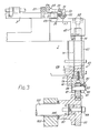
- the parts of the transfer press 1 illustrated in the drawings comprise a transfer slide 3 in the form of a rectangular frame having parallel longitudinally extending sides 4 along the length of which are mounted at equally spaced intervals corresponding with the spacing between the axes of successive rams and dies (not shown), workpiece gripping means 5 one only of such means being shown and said means comprising a pair of arms or fingers 7 in the form of levers which are mounted intermediate their ends on pivot pins 9 disposed normal to the slide 3, At their rearward ends the fingers have mounted thereon workpiece engaging elements 11 having inner part cylindrical surfaces 13 which are engageable with complementarily shaped cylindrical surfaces of the workpieces which they advance through the press from one to the next ram and die.
- coil springs 15 opposite ends of each of which abut respective surfaces of the slide 3 and finger 7 so that the fingers 7 are biassed inwardly towards a closed position of the workpiece engaging elements 11.
- pins 17 Slidably carried in the sides of the slide 3 for movement normal to the direction of motion of the slide are pins 17 which are respectively engaged by the ends of the fingers 7 remote from the elements 11 thereof. Inward movement of the pins, effected as hereinafter described, rotates the fingers 7 against the action of the biassing springs to move the elements 11 to an open position thereof.
- the slide 3 is engaged for reciprocation in a horizontal plane just above the series of dies and below the retracted positions of the rams by a transfer cam (not shown) which co-operates with two cam followers mutually spaced by approximately 180° so that the slide is positively driven throughout its reciprocal movement, whilst at its forward end there is secured, to the sides 4 of the slide by bolts 21, a yoke 23 in which is mounted a pivot shaft 25.
- the latter has mounted thereon a U-shaped lever 27, through parallel limbs 29 of which extends the pivot shaft 25.
- the rods 37 carry a series of crank arms 45 which are secured to the rods 37 by keys 47 and are also adjustably secured against axial movement with respect to the rods by grub screws 49.
- Each of the arms 45 is disposed for engagement with one of the pins 17 so that on rotation of the rods 37 resulting from raising of the bolts 33 on lever 27, the arms 45 are rotated to drive the pins 17 inwards and thus effect opening movement of the workpiece engaging elements 11.
- the springs 15 Upon lowering of the lever 27, the springs 15 cause the fingers 7 to force outwards the pins 17 so that arms 45 rotate the rods 37 in a reverse sense so that contact between the lugs 43 and bolts 33 is maintained whilst the lever 27 is in its lowered position.
- the lever 27, centrally between the limbs 29, is formed on the front end of its under surface with a saddle 53 in which a roller 55 is mounted on a shaft 57.
- the roller 55 engages a plate 59 which is secured to the head 61 of a ram 63 by bolts 65.
- the plate extends rearwardly from the head of the ram so that contact between the roller 55 and plate 59 is maintained throughout the reciprocal movement of the slide 3.
- the ram 63 consists of a body 67 which is bolted to the frame 69 of the press and is formed with a vertical bore 71 lined with a sleeve 73 in which is slidably engaged a rod 75.
- rod 75 has secured thereto by a vertical bolt 77, a block 79 which is saddle shaped and formed with depending side plates 81 through which extends a shaft 83 which is keyed to the block 79 by a key plate 85 held to the block by screw 87. Between the side plates 81 there is mounted on the shaft 83 a cage of needle rollers bearings 89 and a cam follower roller 91 which engages with slide finger opening cam 93. To ensure maintenance of contact between the cam and cam follower, four compression springs 95 are located at corners of the block 79 in cylindrical recesses and extend into coaxial recesses in the body 67.
- the cam 93 is secured to a boss 97 which is bolted by bolt 99 to the bottom drive shaft 101 of the press.
- the bottom drive shaft extends through a part 103 of the frame of the press, a thrust bearing 105 being provided between the frame part 103 and boss 97.
- the bottom drive shaft 101 is driven by an upright side shaft (not shown) which in turn is driven by the main shaft which drives the ram tools.
- the lift profile 107 of the cam extends approximately through 180° of the cam profile.
- the follower 91 maintains the lever 27 in its raised position so that the crank arms 45 acting through the pins 17 open the workpiece engaging elements 11 of the fingers 7.
- the rotation of the cam 93 transfers the follower 91 to the lower profile 109, the lever 27 is lowered and the crank arms 45 are reversely rotated by the action of the finger springs 15 on the pins 17 so that the elements 11 on the fingers 7 are brought to the closed position thereof.
- the setting of the cam 93 in relation to the reciprocal movement of the slide is such that as the slide reaches or closely approaches its rearmost position, the ram tools have raised the workpieces at least partly out of the dies and the cam follower roller, 91 engages the lower profile of the cam so that mechanical closure of the finger elements 11 on the workpieces is effected through the biassing springs 15.
- a stripping mechanism (not shown) of known form operating to ensure positive separation of the workpieces from the ram tools.
- the finger elements 11 remain closed whilst the slide conveys the workpieces forwards till the forward position of the slide is reached or closely approached.
- the cam follower 91 now transfers to the higher profile 107 of the cam and the elements 11 of the fingers 7 open and release the workpieces.
- the ram tools are engaged in the workpieces prior to entering the dies.
- the finger elements 11 then remain open until the slide again reaches or closely approaches its rearmost position and the lower profile is again engaged to allow the finger elements to close on the workpieces under the influence of the springs 15.
- FIG. 6 illustrate mechanism for effecting opening and closing of workpiece engaging means of a transfer press of the same form as is hereinbefore described.
- the workpiece gripping means comprise pairs of fingers 7 each finger being in the form of a lever pivotally mounted intermediate its ends and spring biassed to a closed position so that opening and closing of the workpiece engaging means was effected by rotary movement of the fingers.
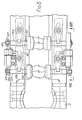
- transfer slide 3 has mounted at equally spaced intervals along its length corresponding with the spacing between the axes of successive rams and dies (not shown), workpiece engaging means 5 which each comprise a pair of opposed fingers 7 including workpiece engaging elements 11 having inner, part cylindrical surfaces 13 which are engageable with complementarily shaped cylindrical surfaces of the workpieces which they advance through the press from one to the next ram and die.
- each rod 151 Extending rearwardly from and normal to the elements 11 are rods 151 which are slidably engaged each in a bore 153 which extends normal to the side 4 of the slide 3. At its outer end each rod 151 has a threaded section 155 on which is carried a lock nut 157 which is adjustable to enable the stroke of the corresponding rod 151 to be varied.
- each rod 151 is formed with a lateral recess 159 in which is engaged one end of a lever 161 which nearer the opposite end thereof is pivotally mounted on a pin 163 normal to the slide.
- each lever 161 is engaged by one of the pins 17 which is moved inwards by a crank arm 45 keyed to rod 37 to effect release of the workpiece engaging means from the workpiece engaged therewith, the rod 37 being rotated in the course of reciprocation of the slide 3.
- Each lever 161 is spring biassed by a spring 165 which embraces the pivot pin 163 and respective ends of which engage an abutment 167 on the lever and a side 169 of an aperture 171 in the slide 3 in which the lever is disposed, the biassing of the spring operating to urge the workpiece engaging means inwards into engagement with the associated workpiece.
- each spring 165 rotates its associated lever 161 to move the rod 151 inwardly and to move the corresponding pin outwardly so that contact between the latter and its corresponding crank arm 45 is maintained.
- the timing of the opening and closing of the workpiece engagement means is effected in the same way and by the same mechanism as described in connection with the embodiment of Figures 1 to 5.
- the mechanism of the invention is simple to manufacture and since the mechanism for opening and closing the fingers is, apart from the cam drive thereof, mounted on the slide, and since the workpiece transfer device actuating means, namely, the slide finger opening and closing mechanism carried on the slide is only connected to the elements of the drive thereof carried on the frame of the press by the contact between the roller 55 of lever 27 and the plate 59 of the ram 63, fitting of the mechanism to existing machines simply involves changing the slide and mounting the cam drive for the new slide on the shaft 101 and bolting its follower ram assembly to the main frame of the press and making minor modifications to the press bolster. It is further possible if desired, to provide that only selected pairs of fingers on the slide are mechanically opened and closed whilst the rest are opened, as hitherto, by frictional engagement between the fingers and the workpieces.
- the mechanism described confers several important advantages on transfer presses of the kind set forth.
- friction between the workpieces and the slide fingers is reduced appreciably with the result that surface damage to the workpieces is reduced as also is damage to the fingers themselves.
- the use of plastic inserts on the slide fingers is also facilitated because of the reduced friction and their use further reduces surface damage to the workpieces.
- the positive opening and closing of the fingers provided by the invention therefore enables high speed running of the press, typically at 240 reciprocations of the slide per minute, whilst avoiding any significant increase in the incidence of surface damage to the workpieces.
- stronger finger biassing springs can be employed without significantly increasing surface damage to the workpieces. The stronger springs ensure that the fingers do not tend to open during high speed operation as a result of the high speed stopping of the slide at the forward end of its travel. This also enables higher speed operation, frictional engagement between the fingers and the workpieces.
Landscapes
- Engineering & Computer Science (AREA)
- Mechanical Engineering (AREA)
- Press Drives And Press Lines (AREA)
Claims (9)
Applications Claiming Priority (4)
| Application Number | Priority Date | Filing Date | Title |
|---|---|---|---|
| GB8516188 | 1985-06-26 | ||
| GB858516188A GB8516188D0 (en) | 1985-06-26 | 1985-06-26 | Transfer press slide finger opening mechanism |
| GB858528956A GB8528956D0 (en) | 1985-11-25 | 1985-11-25 | Transfer press slide finger opening mechanism |
| GB8528956 | 1985-11-25 |
Publications (2)
| Publication Number | Publication Date |
|---|---|
| EP0207659A1 EP0207659A1 (de) | 1987-01-07 |
| EP0207659B1 true EP0207659B1 (de) | 1990-09-05 |
Family
ID=26289423
Family Applications (1)
| Application Number | Title | Priority Date | Filing Date |
|---|---|---|---|
| EP86304449A Expired EP0207659B1 (de) | 1985-06-26 | 1986-06-10 | Greiferöffnungsmechanismus für Förderschienen einer Transferpresse |
Country Status (4)
| Country | Link |
|---|---|
| US (1) | US4750348A (de) |
| EP (1) | EP0207659B1 (de) |
| JP (1) | JPH07100198B2 (de) |
| DE (1) | DE3673896D1 (de) |
Families Citing this family (3)
| Publication number | Priority date | Publication date | Assignee | Title |
|---|---|---|---|---|
| FR2625453A1 (fr) * | 1988-01-04 | 1989-07-07 | Ademva | Outil de presse pour installation d'emboutissage |
| JPH0510993Y2 (de) * | 1988-03-16 | 1993-03-17 | ||
| US4896523A (en) * | 1988-09-02 | 1990-01-30 | The U.S. Baird Corporation | Finger opening mechanism for transfer press |
Family Cites Families (13)
| Publication number | Priority date | Publication date | Assignee | Title |
|---|---|---|---|---|
| US2851979A (en) * | 1954-06-15 | 1958-09-16 | Henry B Chatfield | Transfer device |
| US3057312A (en) * | 1958-05-21 | 1962-10-09 | Meredith R Hatch | Work feed and drive therefor |
| US2934194A (en) * | 1959-01-13 | 1960-04-26 | Bliss E W Co | Work feed console |
| US3707908A (en) * | 1969-12-23 | 1973-01-02 | Schuler Gmbh L | Press equipped with a transfer device |
| US3754667A (en) * | 1972-01-07 | 1973-08-28 | R Storch | Transfer mechanism |
| CH585660A5 (en) * | 1974-11-12 | 1977-03-15 | Km Engineering Ag | Gripper conveyor for thin walled hollow bodies - has series of pivot supported grippers arranged on reciprocating slide to transport workpieces |
| DE2715966C3 (de) * | 1977-04-09 | 1980-03-27 | Hatebur Umformmaschinen Ag, Basel (Schweiz) | Einrichtung zum automatischen Transport von Werkstücken an mehrstufigen Quertransportpressen |
| US4185812A (en) * | 1977-07-18 | 1980-01-29 | Cincinnati Milacron Inc. | Blow molding pallet assembly for conveying one or more workpieces |
| US4273507A (en) * | 1978-12-04 | 1981-06-16 | American Can Company | Transfer mechanism |
| GB2053057B (en) * | 1979-07-11 | 1983-04-27 | American Can Co | Feeding mechanism siutable for can making machines |
| US4404837A (en) * | 1979-07-11 | 1983-09-20 | American Can Company | Press transfer bar |
| US4428221A (en) * | 1982-01-22 | 1984-01-31 | Owens Roland G | Transfer apparatus for straight side press |
| SU1177007A1 (ru) * | 1982-10-29 | 1985-09-07 | Симферопольское Специальное Конструкторское Бюро "Продмаш" | Устройство дл подачи штучных заготовок в многопозиционный пресс |
-
1986
- 1986-06-10 DE DE8686304449T patent/DE3673896D1/de not_active Expired - Fee Related
- 1986-06-10 EP EP86304449A patent/EP0207659B1/de not_active Expired
- 1986-06-13 US US06/874,839 patent/US4750348A/en not_active Expired - Lifetime
- 1986-06-25 JP JP61149348A patent/JPH07100198B2/ja not_active Expired - Lifetime
Also Published As
| Publication number | Publication date |
|---|---|
| JPS6216829A (ja) | 1987-01-26 |
| EP0207659A1 (de) | 1987-01-07 |
| DE3673896D1 (de) | 1990-10-11 |
| JPH07100198B2 (ja) | 1995-11-01 |
| US4750348A (en) | 1988-06-14 |
Similar Documents
| Publication | Publication Date | Title |
|---|---|---|
| US4204824A (en) | Controlled removal of molded parts | |
| US3456814A (en) | Transfer assembly for presses | |
| EP0323695B1 (de) | Pressentransfervorrichtung | |
| CN106031941A (zh) | 一种合模镦锻机及工作方法 | |
| DE1191398B (de) | Werkstueckfoerderwerk, insbesondere fuer eine Haertepresse | |
| DE69819409T2 (de) | Plattenartige Vorrichtung zur Entnahme und zum Transportieren von in einer Warmformpresse warmgeformten Gegenständen | |
| EP0207659B1 (de) | Greiferöffnungsmechanismus für Förderschienen einer Transferpresse | |
| US4621516A (en) | Transfer feed press with transfer feed system | |
| DE2131759A1 (de) | Transporteinrichtung fuer eine Quertransportpresse | |
| US3771669A (en) | Transfer assembly for transferring workpieces from station to station along a press | |
| DE202016100514U1 (de) | Pressensystem | |
| US2314123A (en) | Press unloader | |
| GB1311155A (en) | Apparatus for feeding material to a working machine | |
| US2796616A (en) | Autoamtic transfer mechanism for forging machines and the like | |
| GB949052A (en) | Sampling punch for continuous strip | |
| DE2303659C3 (de) | Vorrichtung zum automatischen Zu- oder Abführen von Werkstucken zu bzw. aus Werkzeugmaschinen | |
| CN210098852U (zh) | 一种多工位侧面双孔冷镦机 | |
| US4419063A (en) | Blow molding detabber | |
| CN208099032U (zh) | 用于机械加工的自动卸料装置 | |
| US4078461A (en) | Trimming press having die movable to inactive position to facilitate scrap removal | |
| US4424742A (en) | Shifting apparatus for a transfer bar of a transfer press | |
| US3431768A (en) | Stock feed mechanism for forging machines and the like | |
| EP0351560B1 (de) | Maschine zum Verändern der Querschnittsform gerundeter Zargen, insbesondere für Dosen | |
| GB2070485A (en) | Extrusion press having a die change assembly | |
| DE3103759A1 (de) | Verfahren und vorrichtung zur herstellung von glaskuelbeln |
Legal Events
| Date | Code | Title | Description |
|---|---|---|---|
| PUAI | Public reference made under article 153(3) epc to a published international application that has entered the european phase |
Free format text: ORIGINAL CODE: 0009012 |
|
| AK | Designated contracting states |
Kind code of ref document: A1 Designated state(s): DE GB IT |
|
| 17P | Request for examination filed |
Effective date: 19870126 |
|
| 17Q | First examination report despatched |
Effective date: 19880119 |
|
| GRAA | (expected) grant |
Free format text: ORIGINAL CODE: 0009210 |
|
| AK | Designated contracting states |
Kind code of ref document: B1 Designated state(s): DE GB IT |
|
| ITF | It: translation for a ep patent filed | ||
| REF | Corresponds to: |
Ref document number: 3673896 Country of ref document: DE Date of ref document: 19901011 |
|
| ITTA | It: last paid annual fee | ||
| PLBE | No opposition filed within time limit |
Free format text: ORIGINAL CODE: 0009261 |
|
| STAA | Information on the status of an ep patent application or granted ep patent |
Free format text: STATUS: NO OPPOSITION FILED WITHIN TIME LIMIT |
|
| 26N | No opposition filed | ||
| REG | Reference to a national code |
Ref country code: GB Ref legal event code: IF02 |
|
| PGFP | Annual fee paid to national office [announced via postgrant information from national office to epo] |
Ref country code: GB Payment date: 20020612 Year of fee payment: 17 |
|
| PG25 | Lapsed in a contracting state [announced via postgrant information from national office to epo] |
Ref country code: GB Free format text: LAPSE BECAUSE OF NON-PAYMENT OF DUE FEES Effective date: 20030610 |
|
| PGFP | Annual fee paid to national office [announced via postgrant information from national office to epo] |
Ref country code: DE Payment date: 20030731 Year of fee payment: 18 |
|
| GBPC | Gb: european patent ceased through non-payment of renewal fee |
Effective date: 20030610 |
|
| PG25 | Lapsed in a contracting state [announced via postgrant information from national office to epo] |
Ref country code: DE Free format text: LAPSE BECAUSE OF NON-PAYMENT OF DUE FEES Effective date: 20050101 |
|
| PG25 | Lapsed in a contracting state [announced via postgrant information from national office to epo] |
Ref country code: IT Free format text: LAPSE BECAUSE OF NON-PAYMENT OF DUE FEES;WARNING: LAPSES OF ITALIAN PATENTS WITH EFFECTIVE DATE BEFORE 2007 MAY HAVE OCCURRED AT ANY TIME BEFORE 2007. THE CORRECT EFFECTIVE DATE MAY BE DIFFERENT FROM THE ONE RECORDED. Effective date: 20050610 |