EP0207660A2 - Dispositif d'actionnement de frein à coin d'écartement - Google Patents
Dispositif d'actionnement de frein à coin d'écartement Download PDFInfo
- Publication number
- EP0207660A2 EP0207660A2 EP86304460A EP86304460A EP0207660A2 EP 0207660 A2 EP0207660 A2 EP 0207660A2 EP 86304460 A EP86304460 A EP 86304460A EP 86304460 A EP86304460 A EP 86304460A EP 0207660 A2 EP0207660 A2 EP 0207660A2
- Authority
- EP
- European Patent Office
- Prior art keywords
- wedge
- cage
- rollers
- stop means
- actuator
- Prior art date
- Legal status (The legal status is an assumption and is not a legal conclusion. Google has not performed a legal analysis and makes no representation as to the accuracy of the status listed.)
- Withdrawn
Links
Images

Classifications
-
- F—MECHANICAL ENGINEERING; LIGHTING; HEATING; WEAPONS; BLASTING
- F16—ENGINEERING ELEMENTS AND UNITS; GENERAL MEASURES FOR PRODUCING AND MAINTAINING EFFECTIVE FUNCTIONING OF MACHINES OR INSTALLATIONS; THERMAL INSULATION IN GENERAL
- F16D—COUPLINGS FOR TRANSMITTING ROTATION; CLUTCHES; BRAKES
- F16D65/00—Parts or details
- F16D65/14—Actuating mechanisms for brakes; Means for initiating operation at a predetermined position
- F16D65/16—Actuating mechanisms for brakes; Means for initiating operation at a predetermined position arranged in or on the brake
- F16D65/22—Actuating mechanisms for brakes; Means for initiating operation at a predetermined position arranged in or on the brake adapted for pressing members apart, e.g. for drum brakes
-
- F—MECHANICAL ENGINEERING; LIGHTING; HEATING; WEAPONS; BLASTING
- F16—ENGINEERING ELEMENTS AND UNITS; GENERAL MEASURES FOR PRODUCING AND MAINTAINING EFFECTIVE FUNCTIONING OF MACHINES OR INSTALLATIONS; THERMAL INSULATION IN GENERAL
- F16D—COUPLINGS FOR TRANSMITTING ROTATION; CLUTCHES; BRAKES
- F16D2125/00—Components of actuators
- F16D2125/18—Mechanical mechanisms
- F16D2125/58—Mechanical mechanisms transmitting linear movement
- F16D2125/66—Wedges
-
- Y—GENERAL TAGGING OF NEW TECHNOLOGICAL DEVELOPMENTS; GENERAL TAGGING OF CROSS-SECTIONAL TECHNOLOGIES SPANNING OVER SEVERAL SECTIONS OF THE IPC; TECHNICAL SUBJECTS COVERED BY FORMER USPC CROSS-REFERENCE ART COLLECTIONS [XRACs] AND DIGESTS
- Y10—TECHNICAL SUBJECTS COVERED BY FORMER USPC
- Y10T—TECHNICAL SUBJECTS COVERED BY FORMER US CLASSIFICATION
- Y10T74/00—Machine element or mechanism
- Y10T74/18—Mechanical movements
- Y10T74/18992—Reciprocating to reciprocating
Definitions
- This invention relates to a wedge-type brake actuator primarily for use in an internal shoe drum brake, and of the general kind in which a pair of rollers associated with respective brake actuating elements are carried by a cage movable along a path normal to the direction of actuating movement of said elements, and a wedge member is reciprocable along said path between the rollers with opposed inclined surfaces thereof engagable respectively with the rollers to urge the rollers and their associated elements outwardly for brake actuation upon movement of the wedge in one direction along said path.
- wedge-type actuators of this general type are generally satisfactory in operation and widely used, for example, on commercial vehicles, it has been found to be possible for the inclined surfaces of the wedge to pass beyond the rollers so that the rollers lodge on the wedge shank behind the wedge proper, making it difficult to achieve satisfactory wedge retraction upon removal of the brake actuation force and possibly giving rise to damage of the rollers and/or wedge shank.
- An object of the invention is to provide an improved wedge-type brake actuator in which the aforesaid problem is minimised or obviated.
- a wedge-type brake actuator of the aforesaid general kind is provided with stop means for limiting movement of the cage relative to the wedge member.
- the stop means is interposed between the cage and means other than the wedge member, said last-named means being preferably an actuating element operable to actuate the wedge member.
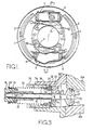
- FIG. 1 this illustrates a two leading shoe drum type brake incorporating a wedge actuator constructed in accordance with an embodiment of the invention.
- the invention is described in conjuction with such a type of drum brake, it should be readily apparent to those skilled in the art that the invention may be applied to any of the known types of wedge actuated brakes.
- the brake includes a backing plate 1 that is adapted to be fixed in any suitable manner to an associated vehicle and which co-operates with a rotating drum (not shown).
- a pair of brake shoes 2 and 3 are slidably supported by the backing plate 1 in known manner and have respective web portions 4.
- a first wheel cylinder indicated generally by the reference numeral 5 has a pair of internal fluid pistons that act against respective plungers 6 which, in turn, engage the ends of the brake shoe webs 4 for urging the brake shoes 2 and 3 outwardly into engagement with the associated drum.
- a second wheel culinder assembly 7 is disposed adjacent the opposite ends of the webs 4 and operates in a similar manner so as to urge the shoes 2 and 3 outwardly into engagement with the rotating drum.
- the cylinder assembly 7 includes a wedge-type actuator constructed in accordance with the invention and indicated generally at 8 ( Figure 2).
- a pair of return springs 9 and 10 are interposed between the webs 4 for retracting the brake in known manner.
- the wedge-type actuator 8 will now be described in more detail in Figure 3 and will be seen to include a wedge member, indicated generally at 11, having a cylindrical shank portion 12 that terminates in a wedge 13 with oppositely facing wedging surfaces 14.
- the surfaces 14 are inclined so that at their inner ends they extend a greater distance than the diameter of the shank 12.
- the wedge 13 has a thickness that is equal to or slightly greater than that of the shank 12.
- the end of the shank 12 remote from the wedge 13 is formed with a rounded nose piece 15 that is adapted to be engaged by a suitable actuator 16 which may be of any conventional type, such as a spring applied fluid pressure release type, or a fluid pressure applied type.
- a cage indicated generally by the reference numeral 17, is formed from sheet metal or the like and has a base portion 18 formed with an opening through which the cylindrical shank 12 of the wedge 11 freely passes.
- a pair of arms 20 extend outwardly and forwardly from the base 18 and are formed with a pair of inclined slots 21.
- Rollers 22 have shank portions 23 that are journaled within the slots 21 in each of the arms 20.
- the rollers 22 are normally held in engagement with the wedge surfaces 14 through their contact with tapered faces of tappet members 22A slidable in the cylinder assembly 7 in conventional manner.
- the wedge actuator 11 is received within an actuator tube 24 that is affixed in a suitable manner to a part 7A of the wheel cylinder housing 7.
- a moulded plastic support 25 has an annular groove in which an 0-ring 26 is received for sealing the support 25 to the end of the actuator tube 24.
- the support 25 may be interference fitted onto one end of a spring 28.
- the opposite end of the spring 28 acts against a retainer 29 which, in turn, encircles a sleeve 30 that is fixed axially to the shank 12 of the wedge actuator 11 by means of a pin 31.
- the spring 28 urges the wedge actuator towards a retracted position.
- the sleeve 25 is held in place by means of a snap ring 32 which is received in an annular groove in the wheel cylinder portion 7A and which engages a retaining ring 33.
- the retaining ring 33 is sealed to the support 25 by means of an 0-ring 34.
- a washer 35 encircles the wedge shank 12 and is normally held in engagement with the retainer 33.
- the brakes are actuated by the wedge actuator in the following manner.
- the actuating member 16 is operated by any of the aforedescribed conventional means so as to urge the wedge 13 to the right as viewed in Figure 3.
- the wedge surfaces 14 will urge the rollers 22 outwardly and cause the inclined surfaces of the tappets 22A to be wedged apart in known manner.
- the cage 18 will move in the same direction but at a slower rate due to the inclined surfaces and the wedging action. Hence, there will be a mechanical advantage exerted on the tappet inclined surfaces so as to cause an amplification in the actuating force of the brake.
- the end of the sleeve 30 will engage the washer 35 and cage 18 before this can occur. At this time, the reaction force exerted by the cage 18 will act directly back through the sleeve 30 to the actuating member 16 so there will be no force amplification in this direction.
- the device offers an extremely rigid stop and yet one which will operate in a very convenient and simple manner.
Landscapes
- Engineering & Computer Science (AREA)
- General Engineering & Computer Science (AREA)
- Mechanical Engineering (AREA)
- Braking Arrangements (AREA)
Applications Claiming Priority (2)
| Application Number | Priority Date | Filing Date | Title |
|---|---|---|---|
| US750500 | 1985-07-01 | ||
| US06/750,500 US4666022A (en) | 1985-07-01 | 1985-07-01 | Wedge-type brake actuator |
Publications (2)
| Publication Number | Publication Date |
|---|---|
| EP0207660A2 true EP0207660A2 (fr) | 1987-01-07 |
| EP0207660A3 EP0207660A3 (fr) | 1987-05-20 |
Family
ID=25018112
Family Applications (1)
| Application Number | Title | Priority Date | Filing Date |
|---|---|---|---|
| EP86304460A Withdrawn EP0207660A3 (fr) | 1985-07-01 | 1986-06-11 | Dispositif d'actionnement de frein à coin d'écartement |
Country Status (7)
| Country | Link |
|---|---|
| US (1) | US4666022A (fr) |
| EP (1) | EP0207660A3 (fr) |
| JP (1) | JPS6231732A (fr) |
| CN (1) | CN1005645B (fr) |
| BR (1) | BR8602967A (fr) |
| ES (1) | ES2008707A6 (fr) |
| IN (1) | IN166696B (fr) |
Families Citing this family (5)
| Publication number | Priority date | Publication date | Assignee | Title |
|---|---|---|---|---|
| JP2001107999A (ja) * | 1999-10-07 | 2001-04-17 | Nisshinbo Ind Inc | ドラムブレーキ装置 |
| US20070227837A1 (en) * | 2006-03-28 | 2007-10-04 | Akebono Corporation (North America) | Wedge roller ramp parking brake assembly |
| DE102011088851B4 (de) * | 2011-12-16 | 2016-08-04 | Saf-Holland Gmbh | Bremsträger |
| CN106195062B (zh) * | 2016-08-31 | 2019-01-11 | 重庆中帝机械制造股份有限公司 | 楔式轮式制动器总成 |
| CN106321690B (zh) * | 2016-08-31 | 2019-01-11 | 重庆中帝机械制造股份有限公司 | 铝合金楔式制动器总成 |
Family Cites Families (14)
| Publication number | Priority date | Publication date | Assignee | Title |
|---|---|---|---|---|
| US3037584A (en) * | 1958-09-02 | 1962-06-05 | Rockwell Standard Co | Wedge actuated brake assembly |
| US3139762A (en) * | 1960-06-24 | 1964-07-07 | Magneti Marelli Spa | Fluid pressure piston actuator |
| US3113466A (en) * | 1961-12-28 | 1963-12-10 | Automotive Prod Co Ltd | Internal shoe drum brakes |
| DE1265511B (de) * | 1964-01-10 | 1968-04-04 | Bendix Corp | Spreizvorrichtung fuer die beiden Bremsbacken einer Innenbackenbremse |
| DE1450098B2 (de) * | 1964-03-25 | 1971-05-19 | Deutsche Perrot Bremse GmbH, 6800 Mannheim Friedrichsfeld | Spreizvorrichtung fuer eine servobremse insbesondere fuer schwere kraftfahrzeuge |
| DE1780600C3 (de) * | 1965-01-29 | 1975-08-07 | Girling Ltd., Birmingham, Warwickshire (Grossbritannien) | Käfig mit Ausnehmungen zur Führung der Rollen einer Fahrzeugbremsbetätigungsvorrichtung |
| GB1151352A (en) * | 1965-06-09 | 1969-05-07 | Girling Ltd | Improvements in and relating to Wedge Type Actuators for Vehicle Brakes |
| DE2147435A1 (de) * | 1971-09-23 | 1973-03-29 | Bosch Gmbh Robert | Betaetigungseinrichtung fuer fahrzeugbremsen |
| DE2260187A1 (de) * | 1971-12-10 | 1973-06-14 | Girling Ltd | Bremsbetaetigungsvorrichtung, insbesondere fuer trommelbremsen |
| DE2343860A1 (de) * | 1972-09-01 | 1974-03-14 | Richard Henry Howard Barr | Keilvorrichtung zur betaetigung von bremsen |
| GB1409335A (en) * | 1973-04-10 | 1975-10-08 | Centrax Ltd | Brakes |
| GB1513244A (en) * | 1974-05-24 | 1978-06-07 | Girling Ltd | Vehicle brakes |
| EP0008876B1 (fr) * | 1978-09-02 | 1982-06-02 | Automotive Products Public Limited Company | Mécanisme d'actionnement d'un frein |
| US4519482A (en) * | 1982-02-05 | 1985-05-28 | Allied Corporation | Wedge actuated drum brake assembly |
-
1985
- 1985-07-01 US US06/750,500 patent/US4666022A/en not_active Expired - Lifetime
-
1986
- 1986-06-11 EP EP86304460A patent/EP0207660A3/fr not_active Withdrawn
- 1986-06-26 BR BR8602967A patent/BR8602967A/pt not_active IP Right Cessation
- 1986-06-30 ES ES8600062A patent/ES2008707A6/es not_active Expired
- 1986-06-30 IN IN496/MAS/86A patent/IN166696B/en unknown
- 1986-07-01 CN CN86104616.1A patent/CN1005645B/zh not_active Expired
- 1986-07-01 JP JP61154951A patent/JPS6231732A/ja active Pending
Also Published As
| Publication number | Publication date |
|---|---|
| ES2008707A6 (es) | 1989-08-01 |
| CN1005645B (zh) | 1989-11-01 |
| IN166696B (fr) | 1990-06-30 |
| JPS6231732A (ja) | 1987-02-10 |
| EP0207660A3 (fr) | 1987-05-20 |
| BR8602967A (pt) | 1987-02-17 |
| CN86104616A (zh) | 1987-01-21 |
| US4666022A (en) | 1987-05-19 |
Similar Documents
| Publication | Publication Date | Title |
|---|---|---|
| US4494630A (en) | Floating-caliper spot-type disc brake | |
| US5251727A (en) | Wear compensating return spring for floating caliper disc brake shoes | |
| US3277983A (en) | Compensating brake structure | |
| US10436269B2 (en) | Active retraction mechanism for low drag caliper brake | |
| US3633715A (en) | Disc brake with spring brake and pressure-compensating self-adjuster | |
| GB1451327A (en) | Brake actuator mechanisms provided with automatic slack adjusters | |
| US20040195056A1 (en) | Retraction mechanism for disc brake assembly | |
| US6564692B2 (en) | Brake booster | |
| US6712362B2 (en) | Primary seals for master-slave cylinder systems | |
| GB1061058A (en) | Improved disc brake | |
| US3651896A (en) | Hydraulic disk brake with mechanical actuator | |
| US5921356A (en) | Adjustable parking brake integrated with service brake | |
| EP0207660A2 (fr) | Dispositif d'actionnement de frein à coin d'écartement | |
| US4519482A (en) | Wedge actuated drum brake assembly | |
| GB2148425A (en) | Improvements in hydraulic actuator assemblies for vehicle brakes | |
| GB2099524A (en) | Disc brake | |
| GB2097876A (en) | A disc brake with caliper retract mechanism | |
| GB1494221A (en) | Brake adjusters | |
| US4294335A (en) | Device for automatically adjusting a braking clearance for a disc brake | |
| US4800993A (en) | Tandem parking brake caliper for disc brakes | |
| US4280603A (en) | Brake applying device | |
| KR870000419B1 (ko) | 일체형 파아크 브레이크 기구 | |
| US4699253A (en) | Brake actuator with automatic adjustment | |
| GB1447359A (en) | Automatic adjusters for vehicle brakes | |
| GB2034836A (en) | Guide device for a brake pad support in a spot type disc brake |
Legal Events
| Date | Code | Title | Description |
|---|---|---|---|
| PUAI | Public reference made under article 153(3) epc to a published international application that has entered the european phase |
Free format text: ORIGINAL CODE: 0009012 |
|
| AK | Designated contracting states |
Kind code of ref document: A2 Designated state(s): DE FR GB IT |
|
| PUAL | Search report despatched |
Free format text: ORIGINAL CODE: 0009013 |
|
| AK | Designated contracting states |
Kind code of ref document: A3 Designated state(s): DE FR GB IT |
|
| 17P | Request for examination filed |
Effective date: 19871120 |
|
| 17Q | First examination report despatched |
Effective date: 19880224 |
|
| STAA | Information on the status of an ep patent application or granted ep patent |
Free format text: STATUS: THE APPLICATION IS DEEMED TO BE WITHDRAWN |
|
| 18D | Application deemed to be withdrawn |
Effective date: 19891021 |
|
| RIN1 | Information on inventor provided before grant (corrected) |
Inventor name: LAYTON, CHARLES THOMAS |