EP0207702A2 - Bouchon d'étrésillon récupérable pour fond de trou - Google Patents
Bouchon d'étrésillon récupérable pour fond de trou Download PDFInfo
- Publication number
- EP0207702A2 EP0207702A2 EP86304784A EP86304784A EP0207702A2 EP 0207702 A2 EP0207702 A2 EP 0207702A2 EP 86304784 A EP86304784 A EP 86304784A EP 86304784 A EP86304784 A EP 86304784A EP 0207702 A2 EP0207702 A2 EP 0207702A2
- Authority
- EP
- European Patent Office
- Prior art keywords
- mandrel
- ratchet
- packer
- bore
- slot
- Prior art date
- Legal status (The legal status is an assumption and is not a legal conclusion. Google has not performed a legal analysis and makes no representation as to the accuracy of the status listed.)
- Granted
Links
Images


Classifications
-
- E—FIXED CONSTRUCTIONS
- E21—EARTH OR ROCK DRILLING; MINING
- E21B—EARTH OR ROCK DRILLING; OBTAINING OIL, GAS, WATER, SOLUBLE OR MELTABLE MATERIALS OR A SLURRY OF MINERALS FROM WELLS
- E21B23/00—Apparatus for displacing, setting, locking, releasing or removing tools, packers or the like in boreholes or wells
- E21B23/004—Indexing systems for guiding relative movement between telescoping parts of downhole tools
- E21B23/006—"J-slot" systems, i.e. lug and slot indexing mechanisms
-
- E—FIXED CONSTRUCTIONS
- E21—EARTH OR ROCK DRILLING; MINING
- E21B—EARTH OR ROCK DRILLING; OBTAINING OIL, GAS, WATER, SOLUBLE OR MELTABLE MATERIALS OR A SLURRY OF MINERALS FROM WELLS
- E21B23/00—Apparatus for displacing, setting, locking, releasing or removing tools, packers or the like in boreholes or wells
- E21B23/06—Apparatus for displacing, setting, locking, releasing or removing tools, packers or the like in boreholes or wells for setting packers
-
- E—FIXED CONSTRUCTIONS
- E21—EARTH OR ROCK DRILLING; MINING
- E21B—EARTH OR ROCK DRILLING; OBTAINING OIL, GAS, WATER, SOLUBLE OR MELTABLE MATERIALS OR A SLURRY OF MINERALS FROM WELLS
- E21B33/00—Sealing or packing boreholes or wells
- E21B33/10—Sealing or packing boreholes or wells in the borehole
- E21B33/12—Packers; Plugs
- E21B33/129—Packers; Plugs with mechanical slips for hooking into the casing
- E21B33/1293—Packers; Plugs with mechanical slips for hooking into the casing with means for anchoring against downward and upward movement
-
- E—FIXED CONSTRUCTIONS
- E21—EARTH OR ROCK DRILLING; MINING
- E21B—EARTH OR ROCK DRILLING; OBTAINING OIL, GAS, WATER, SOLUBLE OR MELTABLE MATERIALS OR A SLURRY OF MINERALS FROM WELLS
- E21B33/00—Sealing or packing boreholes or wells
- E21B33/10—Sealing or packing boreholes or wells in the borehole
- E21B33/13—Methods or devices for cementing, for plugging holes, crevices or the like
- E21B33/134—Bridging plugs
Definitions
- This invention relates to retrievable downhole bridge plugs for use in wells, and more particularly to a packer-type bridge plug which may be set upon a wireline and retrieved upon a tubing string for use in wells.
- a bridge plug which will withstand high differential fluid pressures thereacross, can be set using a wireline and can be easily retrieved from the well.
- Such a bridge plug is particularly desirable when wells with multiple formations are to be isolated for completion, testing and/or stimulation.
- the bridge plug of the present invention comprises mandrel means having a shaped recess thereon, packer mandrel means disposed around the mandrel means and comprising first ratchet means thereon, ratchet body means disposed around the packer mandrel means and comprising second ratchet means thereon for releasably engaging the first ratchet means, mandrel case means disposed around the mandrel means and having lug means thereon for engaging the shaped recess in the mandrel means, packer means on the packer mandrel means for releasably, sealingly engaging a well bore, and slip means for releasably, grippingly engaging the well bore.
- the mandrel case means is shearably attached to the packer mandrel means, and the recess and lug means are positioned below the ratchet body means.
- the mandrel means preferably comprises means thereon for selectively engaging the second ratchet means with the first ratchet means and disengaging the second ratchet means from the first ratchet means corresponding to a relative position of the mandrel means with respect to the packer mandrel means.
- the tool preferably comprises biasing means for biasing the ratchet body means toward the position in which the second ratchet means is engaged with the first ratchet means.
- the slip means preferably comprises upper wedge means, lower wedge means spaced from the upper wedge means, and a plurality of slips disposed between the upper and lower wedge means.
- the slips are engaged with the upper and lower wedge means when in a set position engaging the well bore.
- At least one of the upper and lower wedge means preferably comprises ratchet enclosure means for enclosing and locating the ratchet body means.
- the bridge plug further preferably comprises slip retainer means for retaining the slips and having a portion disposed about the upper wedge means and another portion disposed about the lower wedge means.
- the slip retaining means preferably defines a plurality of apertures therein for permitting extension of a portion of a corresponding slip therethrough.
- the slip retainer means is attached to one of the upper and lower wedge means and is slidable with respect ⁇ to the other of the upper and lower wedge means.
- the mandrel means is preferably a J-slot mandrel having a shaped recess therein
- the mandrel case means is preferably a substantially cylindrical case having a stud threadingly engaged therewith.
- the stud has a lug portion which extends inwardly for engagement with a recess in the mandrel.
- the first ratchet means preferably comprises an external ratchet groove surface on the packer mandrel, and the second ratchet means is best characterised by an internal ratchet groove surface on the ratchet body means.
- bypass means are preferably provided for bypassing fluid through the bridge plug as the bridge plug is retrieved from the well bore.
- the bypass means preferably comprises a bypass body attached to the J-slot mandrel having flow passages therethrough in communication with a central opening through the mandrel.
- a release sleeve valve is preferably disposed around the bypass body and slidable with respect thereto. The release sleeve valve is moved to an open position when the bridge plug is retrieved by a retrieving tool.
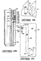
- the wireline set/tubing retrievable bridge plug )f the present invention is shown and generally designated by the numeral 10.
- FIG. lA a portion of bridge plug 10 is shown, including a portion of setting sleeve 12, adapter 14, tension stud 15, and a portion of J-slot receiving mandrel 16.
- Setting sleeve 12 comprises an elongated annular cylindrical member having, on the exterior thereof, a plurality of wrenching flats 22 and cylindrical surface 24 and, on the interior thereof, first annular recess 26, threaded bore 28, second annular recess 30 and cylindrical bore 32.
- Adapter 14 comprises a cylindrical member having, on the exterior thereof, first cylindrical exterior surface 34 and second cylindrical exterior surface 36 and, on the interior thereof, first annular recess 38, first threaded bore 40, second annular recess 42, first cylindrical blind bore 44, a plurality of angled, substantially longitudinally disposed cylindrical bores 46 which allow fluid communication between bore 44 and the exterior of adapter 14, second cylindrical blind bore 48 and second threaded bore 50.
- Adapter 14 further includes first threaded aperture 52, a plurality of apertures 54 which allow fluid communication between bore 44 and the exterior of adapter 14, second threaded aperture 56, and annular recess 58 in end 60 of the adapter.
- Tension stud 15 comprises a cylindrical member having a first threaded end 62 which releasably, threadably engages second threaded bore 50 of adapter 14, a reduced diameter portion 64 and a second threaded end 66.
- J-slot retrieving mandrel 16 shown in ?IG. 1A comprises a cylindrical member having, on the exterior thereof, frusto-conical annular surface 68 and Eirst cylindrical surface 70 having, in turn, a plurality of J-shaped recesses or J-slots 72 therein and, on the interior thereof, a threaded bore 76 releasably, threadedly engaged by threaded end 66 of tension stud 15 and a blind bore 78 in the upper end thereof.
- bridge plug 10 a further portion of bridge plug 10 is shown including the remaining portion of J-slot retrieving mandrel 16, release valve sleeve 18, release valve or bypass body 20, a portion of central J-slot mandrel 120, the remaining portion of setting sleeve 12 and a portion of upper packer shoe 130.
- J-slot retrieving mandrel 16 comprises an elongated cylindrical member having, on the exterior thereof, first cylindrical surface 70 having, in turn, J-shaped recesses 72 and wrenching flats 73 therein, and second cylindrical surface 74 and, on the interior thereof, second threaded bore 80.
- Release valve sleeve 18 has a lower end 19 and comprises an elongated cylindrical annular member having, on the exterior thereof, cylindrical surface 82, and on the interior thereof, bore 84. Release valve sleeve 18 further includes on the upper end, a plurality of longitudinal recesses or grooves 86, an annular rib 88 thereon and at least one threaded aperture 90 therethrough. Each aperture 90 has a portion of a shear pin 91 threadedly engaged therewith.
- Bypass body 20 comprises an elongated cylindrical member having, on the exterior thereof, threaded surface 92 which is releasably, threadedly engaged with threaded bore 80 of J -slot retrieving mandrel 16, first cylindrical surface 94, second cylindrical surface 96 having a plurality of first annular recesses 98 therein containing annular elastomeric seals 100 therein which slidingly, sealingly engage bore 84 of release valve 18 and a second annular recess 99, third cylindrical surface 102 having wrenching flats 104 therein, shoulder 105 and fourth cylindrical surface 106 and, on the interior thereof, blind bore 108, first cylindrical bore 110 having, in turn, annular recess 112 therein containing annu- 5 1ar elastomeric seals 114 therein and threaded bore 116.
- Bypass body 20 further includes a plurality of apertures 118 which allow fluid communication between blind bore 108 and the exterior of bypass body 20 as hereinafter discussed in more detail.
- elastomeric member 119 Installed on first cylindrical surface 94 of bypass body 20 is elastomeric member 119 which resiliently outwardly biases, and sealingly engages, interior bore 84 of release valve sleeve 18 adjacent recesses 86 when sleeve 18 is in a first position on bypass body 20.
- Release valve sleeve 18 is releasably retained on bypass body 20 by threaded shear pin 91 having a body portion thereof extending into annular recess 99 in the bypass body.
- upper end 122 of J-slot nandrel 120 comprises an elongated annular member having, on the exterior thereof, first cylindrical surface 124 which slidingly, sealingly engages seal 114 in first bore 110 of bypass body 20, first threaded surface 126 which threadedly, releasably engages threaded bore 116 of bypass body 20, second cylindrical surface 142 having wrenching flats 127 therein, first frusto-conical surface 144, and a portion of third cylindrical surface 146 and, on the interior thereof, bore 128.
- FIG. 1B Also shown in FIG. 1B is a portion of upper packer shoe 130 comprising an annular cylindrical member having on the exterior thereof, frusto-conical surface 147, first cylindrical surface 148 and, on the interior thereof, first cylindrical bore 152, annular recess 153 having seal 155 therein, and threaded bore 158.
- packer mandrel 138 including, on the exterior thereof, cylindrical surface 163, threaded surface 164 threadedly engaged with threaded bore 158 of upper packer shoe 130 and, on the interior thereof, cylindrical bore 177 having annular recesses 154 therein having seals 156 therein which slidingly, sealingly engage third cylindrical surface 146 of J-slot mandrel 120.
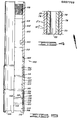
- bridge plug 10 is shown including another portion of J-slot mandrel 120, the remaining portion of upper mandrel shoe 130, packer elements 132, 134 and 136, another portion of packer mandrel L38, lower packer shoe 140, upper wedge 186, slips 226, slip retainer sleeve 250, and a portion of lower wedge 202.
- J-slot mandrel 120 shown in FI G . 1C comprises an elongated cylindrical annular member saving, on the exterior thereof, third cylindrical surface 146 and, on the interior thereof, cylindrical bore 128 therethrough.
- upper packer shoe 130 comprises an annular cylindrical member having, on the exterior thereof, first cylindrical surface 148 and second cylindrical surface 150 and, on the interior thereof, threaded bore 158 and second cylindrical bore 160.
- Lower end 151 of upper packer shoe 130 contacts packer element 132.
- Packer elements 132, 134 and 136 each comprise an annular elastomeric member having a bore 161 therethrough. Exterior surface 165 thereof is adapted for sealing engagement with a well bore as hereinafter described.
- the portion of packer mandrel 138 shown in FIG. 1C comprises an elongated annular cylindrical member having, on the exterior thereof, threaded surface 164 which is threadedly engaged with threaded bore 158 of upper packer shoe 130, second cylindrical surface 166, shoulder 167, third cylindrical surface 168 having a plurality of substantially longitudinal spline members 170 therealong, first frusto-conical annular surface 172, fourth cylindrical surface 174, second frusto-conical annular surface 175 and threaded ratchet groove surface 176.
- bore 177 On the interior of packer mandrel 138 is bore 177.
- Lower packer shoe 140 comprises an annular cylindrical member having, on the exterior thereof, cylindrical surface 178 and, on the interior thereof, cylindrical surface 180, shoulder 181 and threaded bore 182. Upper end 184 of lower packer shoe 140 contacts packer element 136.
- an upper wedge member 186 comprises an annular cylindrical member having, on the exterior thereof, threaded surface 188 threadedly, releasably engaged with threaded bore 182 in lower packer shoe 140, first cylindrical surface 190 having a plurality of wrenching flats 192 therein, second cylindrical surface 194 and frusto-conical surface 196 and, on the interior thereof, bore 198 having a plurality of longitudinal spline members thereon slidably engaged with spline members 170 in packer mandrel 138.
- lower wedge member 202 comprises an elongated, annular cylindrical member having, on the exterior thereof, frusto-conical annular surface 204, first cylindrical surface 206 having, in turn, at least one threaded aperture 208 therein, second cylindrical surface 210 and third cylindrical surface 2l2 forming a recess in surface 210 and, on the interior thereof, a bore 214 and a left-hand threaded bore 218.
- Lower wedge member 202 defines a plurality of rectangular-shaped apertures 220 therethrough having, in turn, an angular top end surface 222 and a bottom end surface 224.
- Slips 226, shown in FIGS. 1C and 1D each comprise an arcuate rectangular-shaped member having a rectangular raised side portion 228 having a plurality of teeth 230 thereon and, on the center of raised side portion 228, a spring guide portion 232 having, in turn, a pair of spring- receiving recesses 234 therein.
- Upper end 236 and lower end 238 of each slip 226 are formed having frusto-conical arcuate surfaces which are complementary to and slidingly engage frusto-conical annular surface 196 of upper wedge member 186 and frusto-conical annular surface 204 of lower wedge member 202, respectively.
- Each slip 226 further includes arcuate interior surface 240 which slidingly engages second cylindrical surface 174 of packer mandrel 138.
- each spring receiving recess 234 in spring guide 232 Disposed in each spring receiving recess 234 in spring guide 232 is a helical coil spring 242 having a first end 244 bearing against a spring seat surface 245 and a second end 246 bearing against inner surface 248 of slip retainer sleeve 250. Springs 242 thus bias slips 226 inwardly toward packer mandrel 138.
- Slip retainer sleeve 250 provides means for retaining and guiding slips 226 and comprises an elongated, annular cylindrical member having, on the exterior thereof, cylindrical surface 252 and, on the interior thereof, bore 254.
- Slip retainer sleeve 250 'further includes a plurality of elongated rectangular apertures 256 therethrough and at least one aperture 258 which receives a portion of threaded member 260 therein to releasably retain slip retainer sleeve 250 to lower wedge nember 202.
- Threaded member 260 threadingly engages threaded aperture 208 in lower wedge member 202.
- J-slot mandrel 120 comprises, on the exterior thereof, third cylindrical surface 146, second frusto-conical surface 262, fourth cylindrical surface 264, third frusto-conical surface 266 and fifth cylindrical surface 268 and, on the interior thereof, bore 128.
- packer mandrel 138 shown in FIG. lD comprises, on the exterior thereof, threaded ratchet groove surface 176, fifth cylindrical surface 270, threaded surface 272 and seventh cylindrical surface 274, and on the interior thereof, bore 177.
- Packer mandrel 138 further includes a plurality of elongated slots 276 therethrough. The upper portion of slots 276 is shown in FIG. 1C and the lower portion in FIG. 1D. Slots 276 extend from approximately upper end 277 of threaded surface 176 to lower end 278 of packer mandrel 138. Slips 276 are aligned with apertures 220 in lower wedge member 202.
- a plurality of ratchet blocks 280 are disposed in apertures 220 and lower wedge member 202 and extend into corresponding slots 276 in packer mandrel 138.
- Each ratchet block 280 comprises a rectangular-shaped member having, on. the exterior thereof, chamfered surface 281 conforming to surface 222 in lower wedge member 202, outer surface 282 having, in turn, a rectangular recess 284 therein containing resilient, annular garter springs 286 and, on the interior :hereof, arcuate smooth surface 292, chamfered surface 294 ind arcuate threaded ratchet groove surfaces 296 which are complementary to ratchet groove surface 176 on packer nandrel 138.
- Each ratchet block 140 further includes upper end surface 298 and lower end surface 300. Bottom surface 300 is complementary to bottom surface 224 of aperture 220 in lower wedge member 202.
- annular support ring 302 Disposed adjacent lower end 278 of packer mandrel 138 is an annular support ring 302 having, on the exterior thereof, first cylindrical surface 304, second cylindrical surface 305, and third cylindrical surface 306, and, on the interior thereof, bore 307.
- a connecting collar 308 has on the exterior thereof first cylindrical surface 310 and, on the interior thereof, threaded bore 312 which is releasably, threadedly engaged with threaded surface 304 on ring 302 and bore 314.
- a second cylindrical surface 316 defines a recess extending inwardly from first cylindrical surface 310 of connecting collar 308.
- Connecting collar 308 has a bottom end 318.
- FIG. 1D Also shown in FIG. 1D is a portion of a J-slot case 320 comprising an elongated annular, cylindrical member having, on the exterior thereof, threaded surface 322 which is threadedly, releasably engaged with threaded bore 218 of lower wedge member 202 and cylindrical surface 324 having, in turn, a threaded aperture 326 therethrough which threadedly receives a portion of a threaded shear pin 328 therein.
- Shear pin 328 has a portion thereof extending into the recess formed by second cylindrical surface 316 of connecting collar 308.
- first bore 330, shoulder 331 and second bore 332 are first bore 330, shoulder 331 and second bore 332.
- J-slot mandrel 120 is shown as comprising an elongated cylindrical annular member having, on the exterior thereof, fifth cylindrical surface 268, shoulder 333 and sixth cylindrical surface 334 having, in turn, at least one J-shaped recess or J-slot 336 formed therein and an aperture or slot 338 therethrough and, on the interior thereof, cylindrical bore 128 therethrough.
- J-slot case 320 shown in FIG. lE comprises an annular cylindrical member having, on the exterior thereof, cylindrical surface 324 having, in turn, a counterbore 340 therein with a first threaded, small aperture 342 therethrough and a second threaded, large aperture 344 therethrough.
- Cylindrical surface 324 further has a threaded aperture 346 therethrough into which is threadingly engaged a shear pin 348 having a portion thereof extending into aperture 338 in J -slot mandrel 120 and, on the interior thereof, cylindrical bore 330 therethrough.
- a threaded stud 350 having a lug portion 351 thereof extending into J-slot 336 in J-slot mandrel 120 and providing lug means for engaging the J-slot.
- Stud 350 has a notch 352 in an outside edge thereof, and threaded member 354 is threaded into aperture 342 such that a head portion thereof fits into notch 352, thus locking stud 350 in place and preventing undesired rotation thereof.
- J-shaped recesses 72 in J-slot retrieving mandrel 16 are shown. Each J -shaped recess is formed having an entry portion 410, ramp portion 412, upper portion 414 and lower portion 416.
- J-slot 336 in J-slot mandrel 120 is shown.
- Each J-slot 336 is formed having an upper portion 420, transition portion 422, ramp portion 423 and lower portion 424.
- Aperture 338 is also shown in FIG. 3.
- the ratchet thread may be of any convenient pitch and diameter.
- a thread having a 30° angle with respect to the vertical plane of the leading face of the thread and a 5° angle with respect to the vertical plane of the trailing face of the thread is preferred.
- Arcuate threaded surface 296 of ratchet blocks 280 are similarly formed.
- Retrieving tool 500 for the retrieval of bridge plug 10 of the present invention is shown.
- Retrieving tool 500 comprises an overshot member '502, upper ring spring holder 504, lower ring spring holder 506 and ring spring 508.
- Overshot member 502 comprises an elongated cylindrical innular member having, on the exterior thereof, first :ylindrical surface 510, threaded surface 512, and second cylindrical surface 514 and, on the interior thereof, threaded bore 516 and bore 518 having, in turn, a plurality of inwardly directed lugs 520 located thereon.
- Overshot nember 502 further includes a plurality of apertures 522 for allowing fluid communication from the exterior thereof to the interior thereof.
- Upper ring spring holder 504 comprises an elongated cylindrical annular member having, on the exterior thereof, first cylindrical surface 524, threaded surface 526 and second cylindrical surface 528 and, on the interior thereof, threaded bore 530 which threadedly, releasably engages threaded surface 512 of overshot member 502, first bore 532, second bore 534 and third bore 536.
- Lower ring spring holder 506 comprises an elongated cylindrical annular member having, on the exterior thereof, cylindrical surface 538 and, on the interior thereof, threaded bore 540 which threadedly engages threaded surface 526 of upper ring spring holder 504, first bore 542 and second bore 544.
- Lower ring spring holder 506 further includes a plurality of recesses 546 in one end thereof.
- Ring spring 508 comprises an annular ring spring having annular frusto-conical annular surfaces 548 therein. Ring spring 502 is retained within first bore 542 of lower ring spring holder 506 having one end thereof abutting annular shoulder 550 of lower ring spring holder 506 while the other end thereof abuts end 552 of upper ring spring holder 504 when holder 504 is secured to holder 506.
- a Baker Model "E-4" Wireline Pressure Setting Assembly (as sold by the Baker Oil Tool Company of H ouston, Texas) is used.
- the Baker Model "E-4" setting assembly is threadedly connected to threaded bore 28 of setting sleeve 12 and threaded bore 40 of adapter 14.
- the setting assembly When the Baker Model "E-4" setting assembly is actuated, the setting assembly causes relative motion between setting sleeve 12 and adapter 14. Initially, upon actuation of the Baker Model "E-4" setting assembly, the setting assembly pulls upwardly on adapter 14 relative to setting sleeve 12. This relative motion causes shearing of shear pins 328, originally securing packer mandrel 138 to J-slot case 320. Upon shearing of shear pins 328, the upward movement by adapter 14 causes corresponding upward movement of J -slot retrieving mandrel 16, bypass body 20, J-slot mandrel 120, J-slot case 320 and lower wedge member 202.
- wedge members 186 and 202 provide wedge means for actuating the slip means. This movement also causes ratchet blocks 280 to engage ratchet groove 176 in packer mandrel 138. Lower end 318 of connecting collar 308 is moved adjacent shoulder 331 in J-slot case 320.
- the Baker Model "E-4" setting assembly causes iownward movement of setting sleeve 12, upper packer shoe L30, packer mandrel 138 and packer elements 132, 134 and 136 relative to retrieving J-slot mandrel 16, bypass body 20, J-slot mandrel 120, lower packer shoe 140, upper wedge member 186, lower wedge member 202 and J-slot case 320.
- ratchet blocks 280 which are engaged with ratchet grooves 176 on packer mandrel 138 act as first and second ratchet means to prevent any relative movement of upper packer shoe 130, packer elements 132, 134 and 136, lower packer shoe 140 and upper wedge member 186 with respect to J-slot retrieving mandrel 16, bypass body 20, J - slot mandrel 120, packer mandrel 138, lower wedge member 202 and J-slot case 320 which would allow bridge plug 10 to unset or disengage the casing in the well bore.
- retrieving tool 500 is connected to a tubing string and lowered into the casing in the well bore.
- Weight is then picked up on the tubing string, raising retrieving tool 500, J-slot retrieving mandrel 16 and J-slot mandrel 120.
- This upward movement of J-slot mandrel 120 causes fifth cylindrical surface 2 68 of the J-slot mandrel to contact surfaces 292 of ratchet blocks 280, acting as means for camming the ratchet blocks outwardly from packer mandrel 138, thus releasing ratchet blocks 280 from engagement with ratchet groove 176 of packer mandrel 138.
- ratchet blocks 280 allows movement of packer mandrel 138 with respect thereto. Shoulder 333 on J - slot mandrel 120 contacts bottom end 318 of connecting collar 308, thus lifting packer mandrel 138 and upper packer shoe 130, thus returning packer elements 132, 134 and 136 to their original positions and therefore no longer in contact with the casing in the well bore.
- Lug 351 on stud 350 on J-slot case 320 then moves downwardly through transition portion 422 of J-slot 336 of J-slot mandrel 120. Ramp portion 423 directs lug 351 into lower portion 424 of J-slot 336.
- Weight is set down on the tubing string again causing lug 351 of stud 350 to move upwardly in lower portion 424 of J-slot 336 to upper surface 425 thereof, which moves J-slot case 320 and lower wedge member 202 downwardly, thereby disengaging lower wedge member 202 from slips 226.
- Springs 242 bias slips 226 inwardly thus disengaging the slips from the casing in the well bore.
- any fluid pressure differential across bridge plug 10 may be equalized by fluid flowing through bore 128 in J-slot mandrel 120, through bore 108 in bypass body 20, through apertures 118 in the bypass body, and through apertures 522 in retrieving tool 500.
- This bypass means facilitates removal of bridge plug 10 from the well bore.
- wireline set/tubing retrievable packer type bridge plug of the present invention is well adapted to carry out the ends and advantages mentioned, as well as those inherent therein. While a presently preferred embodiment of the apparatus is discussed for the purposes of this disclosure, it will be seen that numerous changes in the construction of parts, and various modifications and changes in size, shape and materials, may be made by those skilled in the art. Such changes are encompassed within the scope and spirit of the appended claims.
- bridge plug 10 Illustrations of such modifications and changes in bridge plug 10 are integrating or combining ratchet blocks 280 and lower slip member 202 such that the lower slip member has a plurality of interiorly threaded resilient collet fingers on one end thereof to engage ratchet groove 176 on packer mandrel 138, or integrating or combining lower packer shoe 178 and upper wedge member 186, or integrating or combining packer mandrel 138 and connecting collar 308 into one member, or by rearranging the order of components of bridge plug 10, etc.
- bridge plug 10 of the present invention could be utilized as a packer by changing release valve sleeve 18 to a different type actuating valve to permit the selective flow of fluids through the packer.
Landscapes
- Life Sciences & Earth Sciences (AREA)
- Engineering & Computer Science (AREA)
- Geology (AREA)
- Mining & Mineral Resources (AREA)
- Physics & Mathematics (AREA)
- Environmental & Geological Engineering (AREA)
- Fluid Mechanics (AREA)
- General Life Sciences & Earth Sciences (AREA)
- Geochemistry & Mineralogy (AREA)
- Consolidation Of Soil By Introduction Of Solidifying Substances Into Soil (AREA)
Applications Claiming Priority (4)
| Application Number | Priority Date | Filing Date | Title |
|---|---|---|---|
| US750557 | 1985-06-27 | ||
| US06/750,557 US4648446A (en) | 1985-06-27 | 1985-06-27 | Wireline set/tubing retrieve packer type bridge plug |
| US831249 | 1986-02-19 | ||
| US06/831,249 US4693309A (en) | 1985-06-27 | 1986-02-19 | Wireline set/tubing retrievable bridge plug |
Publications (3)
| Publication Number | Publication Date |
|---|---|
| EP0207702A2 true EP0207702A2 (fr) | 1987-01-07 |
| EP0207702A3 EP0207702A3 (en) | 1988-07-27 |
| EP0207702B1 EP0207702B1 (fr) | 1991-10-16 |
Family
ID=27115293
Family Applications (1)
| Application Number | Title | Priority Date | Filing Date |
|---|---|---|---|
| EP86304784A Expired EP0207702B1 (fr) | 1985-06-27 | 1986-06-20 | Bouchon d'étrésillon récupérable pour fond de trou |
Country Status (4)
| Country | Link |
|---|---|
| US (1) | US4693309A (fr) |
| EP (1) | EP0207702B1 (fr) |
| CA (1) | CA1254506A (fr) |
| DE (1) | DE3681975D1 (fr) |
Cited By (2)
| Publication number | Priority date | Publication date | Assignee | Title |
|---|---|---|---|---|
| GB2240125A (en) * | 1990-01-23 | 1991-07-24 | Otis Eng Co | Packing assembly for use with reeled tubing and method of operating and removing same |
| US6123327A (en) * | 1996-03-13 | 2000-09-26 | Siemens Nixdorf Informationssysteme Aktiengesellschaft | Cash dispenser |
Families Citing this family (19)
| Publication number | Priority date | Publication date | Assignee | Title |
|---|---|---|---|---|
| US5048613A (en) * | 1988-05-31 | 1991-09-17 | Shilling James R | Wireline resettable packoff assembly |
| US4924941A (en) * | 1989-10-30 | 1990-05-15 | Completion Services, Inc. | Bi-directional pressure assisted sealing packers |
| US5224547A (en) * | 1991-04-30 | 1993-07-06 | Halliburton Company | Retrieving tool for downhole packers utilizing non-rotational workstrings |
| US5197547A (en) * | 1992-05-18 | 1993-03-30 | Morgan Allen B | Wireline set packer tool arrangement |
| US5333685A (en) * | 1993-05-14 | 1994-08-02 | Bruce Gilbert | Wireline set and tubing retrievable packer |
| US5449040A (en) * | 1994-10-04 | 1995-09-12 | Milner; John E. | Wireline-set tubing-release packer apparatus |
| GB2360055B (en) * | 1997-07-03 | 2001-12-05 | Baker Hughes Inc | Thru-tubing packer release devices |
| CA2224917C (fr) * | 1998-01-23 | 2004-12-14 | William Jani | Bouchon d'obstruction amelioree pour un puits de forage |
| US6220348B1 (en) | 1998-10-20 | 2001-04-24 | Polar Completions Engineering Inc. | Retrievable bridge plug and retrieving tool |
| US6257339B1 (en) | 1999-10-02 | 2001-07-10 | Weatherford/Lamb, Inc | Packer system |
| US6666275B2 (en) | 2001-08-02 | 2003-12-23 | Halliburton Energy Services, Inc. | Bridge plug |
| US7082991B2 (en) * | 2002-04-18 | 2006-08-01 | Team Oil Tools | Slip spring with heel notch |
| US7591305B2 (en) * | 2002-04-18 | 2009-09-22 | Tejas Complete Solutions, Lp | Patriot retrievable production packer |
| US6880642B1 (en) | 2002-11-21 | 2005-04-19 | Jonathan Garrett | Well abandonment plug |
| US6823944B2 (en) * | 2003-02-06 | 2004-11-30 | Tryad Service Corporation | Apparatus and method for completing a well |
| GB2460474B (en) * | 2008-05-31 | 2012-02-29 | Red Spider Technology Ltd | Large bore packer |
| US8505623B2 (en) * | 2009-08-11 | 2013-08-13 | Weatherford/Lamb, Inc. | Retrievable bridge plug |
| US8991485B2 (en) | 2010-11-23 | 2015-03-31 | Wireline Solutions, Llc | Non-metallic slip assembly and related methods |
| CN114607316B (zh) * | 2022-04-21 | 2023-05-12 | 西南石油大学 | 一种可回收桥塞 |
Family Cites Families (16)
| Publication number | Priority date | Publication date | Assignee | Title |
|---|---|---|---|---|
| US3244233A (en) * | 1963-04-04 | 1966-04-05 | Halliburton Co | Retrievable bridge plug |
| US3507327A (en) * | 1964-09-04 | 1970-04-21 | Baker Oil Tools Inc | Retrievable subsurface well tools |
| US3584684A (en) * | 1969-06-02 | 1971-06-15 | Halliburton Co | Retrievable packer apparatus for use in a well bore and method of prolonging its operating life |
| US3643737A (en) * | 1970-11-27 | 1972-02-22 | Camco Inc | Slip assembly for a well tool |
| US3746090A (en) * | 1971-06-21 | 1973-07-17 | Dresser Ind | Latch or retrievable well packer |
| US3722588A (en) * | 1971-10-18 | 1973-03-27 | J Tamplen | Seal assembly |
| US3749166A (en) * | 1972-05-26 | 1973-07-31 | Schlumberger Technology Corp | Well packer apparatus |
| US3749167A (en) * | 1972-05-26 | 1973-07-31 | Schlumberger Technology Corp | Well tool anchoring apparatus |
| US4044826A (en) * | 1976-05-17 | 1977-08-30 | Baker International Corporation | Retrievable well packers |
| US4078606A (en) * | 1976-12-15 | 1978-03-14 | Brown Oil Tools, Inc. | Pressure actuated holding apparatus |
| US4436150A (en) * | 1981-09-28 | 1984-03-13 | Otis Engineering Corporation | Bridge plug |
| US4427063A (en) * | 1981-11-09 | 1984-01-24 | Halliburton Company | Retrievable bridge plug |
| US4518037A (en) * | 1981-12-10 | 1985-05-21 | Youngblood Harold C | Retrievable well tool |
| US4526229A (en) * | 1983-02-14 | 1985-07-02 | Gulf Oil Corporation | Hydraulic packer assembly |
| US4524825A (en) * | 1983-12-01 | 1985-06-25 | Halliburton Company | Well packer |
| US4545431A (en) * | 1984-05-23 | 1985-10-08 | Halliburton Company | Wireline set/tubing retrieve packer type bridge plug |
-
1986
- 1986-02-19 US US06/831,249 patent/US4693309A/en not_active Expired - Lifetime
- 1986-06-20 EP EP86304784A patent/EP0207702B1/fr not_active Expired
- 1986-06-20 DE DE8686304784T patent/DE3681975D1/de not_active Expired - Fee Related
- 1986-06-26 CA CA000512520A patent/CA1254506A/fr not_active Expired
Cited By (3)
| Publication number | Priority date | Publication date | Assignee | Title |
|---|---|---|---|---|
| GB2240125A (en) * | 1990-01-23 | 1991-07-24 | Otis Eng Co | Packing assembly for use with reeled tubing and method of operating and removing same |
| GB2240125B (en) * | 1990-01-23 | 1994-08-10 | Otis Eng Co | Packing assembly for use with reeled tubing and method of operating and removing same |
| US6123327A (en) * | 1996-03-13 | 2000-09-26 | Siemens Nixdorf Informationssysteme Aktiengesellschaft | Cash dispenser |
Also Published As
| Publication number | Publication date |
|---|---|
| DE3681975D1 (de) | 1991-11-21 |
| EP0207702A3 (en) | 1988-07-27 |
| US4693309A (en) | 1987-09-15 |
| EP0207702B1 (fr) | 1991-10-16 |
| CA1254506A (fr) | 1989-05-23 |
Similar Documents
| Publication | Publication Date | Title |
|---|---|---|
| EP0207702B1 (fr) | Bouchon d'étrésillon récupérable pour fond de trou | |
| EP0383494B1 (fr) | Bouchon de pontage réutilisable et dispositif d'étanchement | |
| US4545431A (en) | Wireline set/tubing retrieve packer type bridge plug | |
| EP0578681B1 (fr) | Bouchon-pont recuperable et outil de descente associe | |
| US4862966A (en) | Liner hanger with collapsible ball valve seat | |
| US5178219A (en) | Method and apparatus for performing a block squeeze cementing job | |
| US8136588B2 (en) | Downhole tool and running tool system for retrievably setting a downhole tool at locations within a well bore | |
| US5333685A (en) | Wireline set and tubing retrievable packer | |
| US6666275B2 (en) | Bridge plug | |
| CA2139067C (fr) | Appareil de tassement a degagement de gaine pour cables | |
| US5197547A (en) | Wireline set packer tool arrangement | |
| US4648446A (en) | Wireline set/tubing retrieve packer type bridge plug | |
| US4828037A (en) | Liner hanger with retrievable ball valve seat | |
| US6131663A (en) | Method and apparatus for positioning and repositioning a plurality of service tools downhole without rotation | |
| US5143015A (en) | Coiled tubing set inflatable packer, bridge plug and releasing tool therefor | |
| US5343956A (en) | Coiled tubing set and released resettable inflatable bridge plug | |
| US20240309726A1 (en) | Jettisonable ball seal | |
| US4610300A (en) | Tubing actuated retrievable packer | |
| US4793411A (en) | Retrievable gravel packer and retrieving tool | |
| US4842057A (en) | Retrievable gravel packer and retrieving tool | |
| EP0349335B1 (fr) | Bouchon pour packer de filtre à gravier | |
| US4722400A (en) | Mechanically actuated subsurface injection tool | |
| EP0233068A2 (fr) | Outil de pose pour dispositif de packer pour l'équipement d'un zone avec un filtre à gravier | |
| GB2348903A (en) | Retrievable bridge plug and packer forming an isolated zone | |
| CA2452125C (fr) | Methode et appareil pour le positionnement et repositionnement sans tournoiement d'une pluralite d'outils dans un forage |
Legal Events
| Date | Code | Title | Description |
|---|---|---|---|
| PUAI | Public reference made under article 153(3) epc to a published international application that has entered the european phase |
Free format text: ORIGINAL CODE: 0009012 |
|
| AK | Designated contracting states |
Kind code of ref document: A2 Designated state(s): DE FR GB IT NL |
|
| PUAL | Search report despatched |
Free format text: ORIGINAL CODE: 0009013 |
|
| AK | Designated contracting states |
Kind code of ref document: A3 Designated state(s): DE FR GB IT NL |
|
| 17P | Request for examination filed |
Effective date: 19890113 |
|
| 17Q | First examination report despatched |
Effective date: 19890710 |
|
| GRAA | (expected) grant |
Free format text: ORIGINAL CODE: 0009210 |
|
| AK | Designated contracting states |
Kind code of ref document: B1 Designated state(s): DE FR GB IT NL |
|
| ITF | It: translation for a ep patent filed | ||
| REF | Corresponds to: |
Ref document number: 3681975 Country of ref document: DE Date of ref document: 19911121 |
|
| ET | Fr: translation filed | ||
| PLBE | No opposition filed within time limit |
Free format text: ORIGINAL CODE: 0009261 |
|
| STAA | Information on the status of an ep patent application or granted ep patent |
Free format text: STATUS: NO OPPOSITION FILED WITHIN TIME LIMIT |
|
| 26N | No opposition filed | ||
| PGFP | Annual fee paid to national office [announced via postgrant information from national office to epo] |
Ref country code: DE Payment date: 19940223 Year of fee payment: 8 |
|
| PGFP | Annual fee paid to national office [announced via postgrant information from national office to epo] |
Ref country code: FR Payment date: 19940609 Year of fee payment: 9 |
|
| PGFP | Annual fee paid to national office [announced via postgrant information from national office to epo] |
Ref country code: GB Payment date: 19940610 Year of fee payment: 9 |
|
| PGFP | Annual fee paid to national office [announced via postgrant information from national office to epo] |
Ref country code: NL Payment date: 19940630 Year of fee payment: 9 |
|
| PG25 | Lapsed in a contracting state [announced via postgrant information from national office to epo] |
Ref country code: DE Effective date: 19950301 |
|
| PG25 | Lapsed in a contracting state [announced via postgrant information from national office to epo] |
Ref country code: GB Effective date: 19950620 |
|
| PG25 | Lapsed in a contracting state [announced via postgrant information from national office to epo] |
Ref country code: NL Effective date: 19960101 |
|
| GBPC | Gb: european patent ceased through non-payment of renewal fee |
Effective date: 19950620 |
|
| PG25 | Lapsed in a contracting state [announced via postgrant information from national office to epo] |
Ref country code: FR Effective date: 19960229 |
|
| NLV4 | Nl: lapsed or anulled due to non-payment of the annual fee |
Effective date: 19960101 |
|
| REG | Reference to a national code |
Ref country code: FR Ref legal event code: ST |
|
| PG25 | Lapsed in a contracting state [announced via postgrant information from national office to epo] |
Ref country code: IT Free format text: LAPSE BECAUSE OF NON-PAYMENT OF DUE FEES;WARNING: LAPSES OF ITALIAN PATENTS WITH EFFECTIVE DATE BEFORE 2007 MAY HAVE OCCURRED AT ANY TIME BEFORE 2007. THE CORRECT EFFECTIVE DATE MAY BE DIFFERENT FROM THE ONE RECORDED. Effective date: 20050620 |