EP0207768A2 - Beschichtungsverfahren - Google Patents
Beschichtungsverfahren Download PDFInfo
- Publication number
- EP0207768A2 EP0207768A2 EP86305044A EP86305044A EP0207768A2 EP 0207768 A2 EP0207768 A2 EP 0207768A2 EP 86305044 A EP86305044 A EP 86305044A EP 86305044 A EP86305044 A EP 86305044A EP 0207768 A2 EP0207768 A2 EP 0207768A2
- Authority
- EP
- European Patent Office
- Prior art keywords
- coating
- substrate
- cathode
- bias
- released
- Prior art date
- Legal status (The legal status is an assumption and is not a legal conclusion. Google has not performed a legal analysis and makes no representation as to the accuracy of the status listed.)
- Withdrawn
Links
- 238000000576 coating method Methods 0.000 title claims abstract description 56
- 239000011248 coating agent Substances 0.000 title claims abstract description 51
- 239000000758 substrate Substances 0.000 claims abstract description 36
- 239000000463 material Substances 0.000 claims abstract description 26
- 238000007733 ion plating Methods 0.000 claims abstract description 11
- 238000010849 ion bombardment Methods 0.000 claims abstract description 4
- 238000000034 method Methods 0.000 claims description 20
- 229910052782 aluminium Inorganic materials 0.000 claims description 9
- 239000004411 aluminium Substances 0.000 claims description 7
- XAGFODPZIPBFFR-UHFFFAOYSA-N aluminium Chemical compound [Al] XAGFODPZIPBFFR-UHFFFAOYSA-N 0.000 claims description 7
- 238000005513 bias potential Methods 0.000 claims description 6
- 229910052727 yttrium Inorganic materials 0.000 claims description 6
- VWQVUPCCIRVNHF-UHFFFAOYSA-N yttrium atom Chemical compound [Y] VWQVUPCCIRVNHF-UHFFFAOYSA-N 0.000 claims description 6
- 229910000831 Steel Inorganic materials 0.000 claims description 2
- 239000010959 steel Substances 0.000 claims description 2
- 229910000838 Al alloy Inorganic materials 0.000 claims 1
- 229910045601 alloy Inorganic materials 0.000 abstract description 8
- 239000000956 alloy Substances 0.000 abstract description 8
- 238000005498 polishing Methods 0.000 abstract description 3
- 230000014759 maintenance of location Effects 0.000 abstract 1
- 239000007789 gas Substances 0.000 description 8
- 238000005086 pumping Methods 0.000 description 7
- PXHVJJICTQNCMI-UHFFFAOYSA-N nickel Substances [Ni] PXHVJJICTQNCMI-UHFFFAOYSA-N 0.000 description 4
- 238000004544 sputter deposition Methods 0.000 description 4
- 238000005260 corrosion Methods 0.000 description 3
- 230000007797 corrosion Effects 0.000 description 3
- 229910052759 nickel Inorganic materials 0.000 description 3
- VYPSYNLAJGMNEJ-UHFFFAOYSA-N Silicium dioxide Chemical compound O=[Si]=O VYPSYNLAJGMNEJ-UHFFFAOYSA-N 0.000 description 2
- 239000004020 conductor Substances 0.000 description 2
- 230000000694 effects Effects 0.000 description 2
- 239000012212 insulator Substances 0.000 description 2
- 150000002500 ions Chemical class 0.000 description 2
- 229910052751 metal Inorganic materials 0.000 description 2
- 239000002184 metal Substances 0.000 description 2
- 150000002739 metals Chemical class 0.000 description 2
- 239000011368 organic material Substances 0.000 description 2
- 230000003647 oxidation Effects 0.000 description 2
- 238000007254 oxidation reaction Methods 0.000 description 2
- 238000005546 reactive sputtering Methods 0.000 description 2
- OKTJSMMVPCPJKN-UHFFFAOYSA-N Carbon Chemical compound [C] OKTJSMMVPCPJKN-UHFFFAOYSA-N 0.000 description 1
- VYZAMTAEIAYCRO-UHFFFAOYSA-N Chromium Chemical compound [Cr] VYZAMTAEIAYCRO-UHFFFAOYSA-N 0.000 description 1
- XUIMIQQOPSSXEZ-UHFFFAOYSA-N Silicon Chemical compound [Si] XUIMIQQOPSSXEZ-UHFFFAOYSA-N 0.000 description 1
- RTAQQCXQSZGOHL-UHFFFAOYSA-N Titanium Chemical compound [Ti] RTAQQCXQSZGOHL-UHFFFAOYSA-N 0.000 description 1
- PNEYBMLMFCGWSK-UHFFFAOYSA-N aluminium oxide Inorganic materials [O-2].[O-2].[O-2].[Al+3].[Al+3] PNEYBMLMFCGWSK-UHFFFAOYSA-N 0.000 description 1
- 239000012300 argon atmosphere Substances 0.000 description 1
- 229910052799 carbon Inorganic materials 0.000 description 1
- 239000010406 cathode material Substances 0.000 description 1
- 239000000919 ceramic Substances 0.000 description 1
- 229910052804 chromium Inorganic materials 0.000 description 1
- 239000011651 chromium Substances 0.000 description 1
- 238000001816 cooling Methods 0.000 description 1
- 238000000280 densification Methods 0.000 description 1
- 238000010586 diagram Methods 0.000 description 1
- 238000010894 electron beam technology Methods 0.000 description 1
- 238000005516 engineering process Methods 0.000 description 1
- 238000001704 evaporation Methods 0.000 description 1
- 230000008020 evaporation Effects 0.000 description 1
- 238000010438 heat treatment Methods 0.000 description 1
- 238000012423 maintenance Methods 0.000 description 1
- 238000004519 manufacturing process Methods 0.000 description 1
- 229910052750 molybdenum Inorganic materials 0.000 description 1
- 238000010943 off-gassing Methods 0.000 description 1
- 229910052710 silicon Inorganic materials 0.000 description 1
- 239000010703 silicon Substances 0.000 description 1
- 239000000377 silicon dioxide Substances 0.000 description 1
- -1 steels (e.g. mild Chemical class 0.000 description 1
- 239000010936 titanium Substances 0.000 description 1
- 229910052719 titanium Inorganic materials 0.000 description 1
- WFKWXMTUELFFGS-UHFFFAOYSA-N tungsten Chemical compound [W] WFKWXMTUELFFGS-UHFFFAOYSA-N 0.000 description 1
- 229910052721 tungsten Inorganic materials 0.000 description 1
- 239000010937 tungsten Substances 0.000 description 1
Images
Classifications
-
- C—CHEMISTRY; METALLURGY
- C23—COATING METALLIC MATERIAL; COATING MATERIAL WITH METALLIC MATERIAL; CHEMICAL SURFACE TREATMENT; DIFFUSION TREATMENT OF METALLIC MATERIAL; COATING BY VACUUM EVAPORATION, BY SPUTTERING, BY ION IMPLANTATION OR BY CHEMICAL VAPOUR DEPOSITION, IN GENERAL; INHIBITING CORROSION OF METALLIC MATERIAL OR INCRUSTATION IN GENERAL
- C23C—COATING METALLIC MATERIAL; COATING MATERIAL WITH METALLIC MATERIAL; SURFACE TREATMENT OF METALLIC MATERIAL BY DIFFUSION INTO THE SURFACE, BY CHEMICAL CONVERSION OR SUBSTITUTION; COATING BY VACUUM EVAPORATION, BY SPUTTERING, BY ION IMPLANTATION OR BY CHEMICAL VAPOUR DEPOSITION, IN GENERAL
- C23C14/00—Coating by vacuum evaporation, by sputtering or by ion implantation of the coating forming material
- C23C14/06—Coating by vacuum evaporation, by sputtering or by ion implantation of the coating forming material characterised by the coating material
- C23C14/14—Metallic material, boron or silicon
- C23C14/16—Metallic material, boron or silicon on metallic substrates or on substrates of boron or silicon
- C23C14/165—Metallic material, boron or silicon on metallic substrates or on substrates of boron or silicon by cathodic sputtering
-
- C—CHEMISTRY; METALLURGY
- C23—COATING METALLIC MATERIAL; COATING MATERIAL WITH METALLIC MATERIAL; CHEMICAL SURFACE TREATMENT; DIFFUSION TREATMENT OF METALLIC MATERIAL; COATING BY VACUUM EVAPORATION, BY SPUTTERING, BY ION IMPLANTATION OR BY CHEMICAL VAPOUR DEPOSITION, IN GENERAL; INHIBITING CORROSION OF METALLIC MATERIAL OR INCRUSTATION IN GENERAL
- C23C—COATING METALLIC MATERIAL; COATING MATERIAL WITH METALLIC MATERIAL; SURFACE TREATMENT OF METALLIC MATERIAL BY DIFFUSION INTO THE SURFACE, BY CHEMICAL CONVERSION OR SUBSTITUTION; COATING BY VACUUM EVAPORATION, BY SPUTTERING, BY ION IMPLANTATION OR BY CHEMICAL VAPOUR DEPOSITION, IN GENERAL
- C23C14/00—Coating by vacuum evaporation, by sputtering or by ion implantation of the coating forming material
- C23C14/22—Coating by vacuum evaporation, by sputtering or by ion implantation of the coating forming material characterised by the process of coating
- C23C14/54—Controlling or regulating the coating process
- C23C14/541—Heating or cooling of the substrates
Definitions
- This invention relates to the coating of substrates by sputter ion plating.
- Sputter ion plating is a known coating technique and involves the transfer of material from a cathode to a substrate in the presence of a DC glow discharge in a soft vacuum chamber wherein the material is generated from the cathode by the action of ion bombardment, i.e. sputtering, and ultimately diffuses to the substrate to form a coating thereon.
- Sputter ion plating is described in detail in a number of references in the art, for example in Proc. conf. on 'Ion plating and Allied Techniques', Edinburgh, 1977, CEP Consultants, Edinburgh, 177 by R.A. Dugdale; Metals Technology 1982, 9 , 499 by J.P. Coad and J.E. Restall; and NATO Advanced Workshop on 'Coatings for Heat Engines', Acquafredda di Maratea, Italy, April 1984 by J.P. Coad and D.S. Rickerby.
- a negative bias voltage may advantageously be applied to the coated substrate to cause densification of the coating by resputtering of deposited material and ion polishing.
- a negative bias voltage applied in this way may, however, give rise to problems.
- the coating material includes Al, which is difficult to control using sputter ion plating, and where the substrate has parts such as edges where the bias field is concentrated, the concentration of Al in the coating produced on those parts is markedly reduced.
- the invention is concerned with ameliorating the above-mentioned problem and provides a method of forming a coating on a substrate by sputter ion plating comprising generating a DC glow discharge under soft vacuum conditions in the presence of the substrate and of a cathode constituted by the coating material thereby to release material at the cathode by ion bombardment, which released material diffuses to the substrate to form the coating thereon, and, during said coating, applying an AC bias potential to the substrate thereby to control the properties of the coating.
- the waveform of the bias potential may be of any shape that enables negative voltages to be applied to the substrate for part of the time during which coating is taking place.
- it may be sinusoidal, rectangular, or any convenient shape. It need not necessarily be of fixed frequency nor of balanced positive and negative amplitude.
- Use of an AC bias has the advantage that the maximum voltage (which causes the Al to sputter away most readily) is applied for only a fraction of the time.
- a 240 volts AC supply may be suitable; by choosing the appropriate input phase, the phase of the AC bias may be varied to match the power supply providing the main sputtering power.
- the method may be carried out in the presence of a reactive gas (e.g. O2 or N2) that reacts with the released material to form a coating that is chemically different from the released material.
- a reactive gas e.g. O2 or N2
- This is known in the art as 'reactive sputtering'.
- the invention is suited to the production of coatings containing elements which have a low threshold energy for sputtering.
- elements are aluminium, which has been mentioned above, and yttrium.
- materials containing such elements are high temperature coating alloys, for example, those falling within the general formula MCrAlY such as CoCrAlY and NiCoCrAlY; NiCrAlTi; and NiCrAlSi.
- substrate materials include metals such as steels (e.g. mild, carbon or stainless), Al and Al base alloys, Ta, Cu, Mo and Ni and Ni base alloys; and ceramics such as silica and alumina.
- the invention is particularly useful for coating substrates having relatively sharp edges since loss of coating material at such edges may be avoided.
- substrates are aerofoil components in gas turbine engines. Of particular value for such applications is the finding that NiCrAlSi coatings produced by the method of the invention possess outstanding resistance to corrosion.
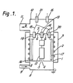
- an earthed cylindrical coating chamber 1 is provided with an externally mounted resistance heater 2 having a cooling jacket 3.
- the coating chamber 1 has a gas inlet vent 4 with an associated baffle 5 and gas outlet vents 6 with associated baffles 7.
- the inlet vent 4 communicates with a getter chamber 8 provided with an inlet conduit 9 and the outlet vents 6 communicate with a pumping chamber 10 provided with a pumping port 11.
- a substrate 12 is mounted in the coating chamber 1 and is electrically connected to a bias potential power supply (now shown) by a conductor 13 mounted in insulators 14 and 15 positioned in the walls of the pumping chamber 10.
- a cathode in the form of series of target plates of which two 16 and 17 are shown is also mounted within the coating chamber 1.
- the cathode e.g. 16 and 17
- the cathode is electrically connected to a cathode power supply (not shown) by a conductor 18 mounted in insulators 19, 20 and 21 positioned in the walls of the pumping chamber 10.
- an operating gas is supplied at the inlet conduit 9 and, by operation of a pump (not shown) at the pumping port 11, is drawn into the getter chamber 8 as shown by arrow a and thence into the coating chamber 1 via inlet vent 4.
- the coating chamber 1 is heated by means of the heater 2 in order to outgas the substrate 12, cathode (e.g. 16 & 17) and evaporate any organic material.
- Undesired gas and vapour leave the coating chamber 1 via the outlet vents 6 to enter the pumping chamber 10 and are removed via the pumping port 11 as shown by arrow b .
- a high negative voltage is applied to the target plates (e.g.
- the apparatus shown in the Figure was used.
- the coating chamber 1 was pumped down to 10-100 m torr pressure with a flowing high purity argon atmosphere purified by passing over freshly deposited titanium.
- the coating chamber 1 was heated to a temperature of around 300°C to effect outgassing of the substrate 12 and the cathode e.g. 16 and 17 and evaporation of any organic material.
- a high negative voltage typically 400V to 1500V was then applied to the cathode e.g. 16 and 17 to produce a glow discharge with net transfer of material therefrom to the substrate 12 to effect coating thereof.
- An AC bias from a 240V AC supply (10 to 100 volts RMS) was applied to the coated substrate 8 to densify the coating. Where reactive sputtering was required, a reactive gas was admitted to the coating chamber 1 at a small partial pressure (1 to 100 m torr) during the coating process.
- the above procedure was used to coat a substrate having sharp edges with a CoCrAlY alloy to confer high temperature oxidation and hot corrosion resistance properties, the cathode comprising the CoCrAlY alloy.
- the procedure was also used to coat substrate samples in the form of IN600 test coupons with an yttrium containing coating and substrate samples in the form of turbine blades having sharply radiused edges with an aluminium containing coating.
- the AC bias applied to the samples was 50V AC. In the former case, the yttrium concentration of the coated samples was measured on a flat surface and in the latter case, the aluminium concentration of the coated samples was measured at an edge thereof.
- turbine blades were coated with an alloy based on nickel, chromium, aluminium and silicon (a NiCrAlSi alloy) and the coated blades tested for several hundred hours under arduous corrosive conditions in a marine gas turbine engine.
- a NiCrAlSi alloy an alloy based on nickel, chromium, aluminium and silicon
- the coating was found to have performed considerably better than commercially available Pt-Al and some proprietory electron beam evaporated CoCrAlY coatings.
Landscapes
- Chemical & Material Sciences (AREA)
- Chemical Kinetics & Catalysis (AREA)
- Engineering & Computer Science (AREA)
- Materials Engineering (AREA)
- Mechanical Engineering (AREA)
- Metallurgy (AREA)
- Organic Chemistry (AREA)
- Physical Vapour Deposition (AREA)
- Cutting Tools, Boring Holders, And Turrets (AREA)
Applications Claiming Priority (4)
| Application Number | Priority Date | Filing Date | Title |
|---|---|---|---|
| GB8516580 | 1985-07-01 | ||
| GB858516580A GB8516580D0 (en) | 1985-07-01 | 1985-07-01 | Coating improvements |
| GB8526948 | 1985-11-01 | ||
| GB858526948A GB8526948D0 (en) | 1985-07-01 | 1985-11-01 | Coating improvements |
Publications (2)
| Publication Number | Publication Date |
|---|---|
| EP0207768A2 true EP0207768A2 (de) | 1987-01-07 |
| EP0207768A3 EP0207768A3 (de) | 1987-08-05 |
Family
ID=26289443
Family Applications (1)
| Application Number | Title | Priority Date | Filing Date |
|---|---|---|---|
| EP86305044A Withdrawn EP0207768A3 (de) | 1985-07-01 | 1986-06-27 | Beschichtungsverfahren |
Country Status (3)
| Country | Link |
|---|---|
| US (1) | US4885069A (de) |
| EP (1) | EP0207768A3 (de) |
| GB (1) | GB2178061B (de) |
Cited By (2)
| Publication number | Priority date | Publication date | Assignee | Title |
|---|---|---|---|---|
| WO1988009397A1 (en) * | 1987-05-18 | 1988-12-01 | The Secretary Of State For Defence In Her Britanni | COATED NEAR -alpha TITANIUM ARTICLES |
| EP0297502A3 (en) * | 1987-06-30 | 1989-05-24 | Hitachi, Ltd. | Method of and apparatus for sputtering, and integrated circuit device |
Families Citing this family (10)
| Publication number | Priority date | Publication date | Assignee | Title |
|---|---|---|---|---|
| DE3737404A1 (de) * | 1987-11-04 | 1989-05-18 | Bartl Josef Franz | Verfahren und einrichtung zur erzeugung haftfester vakuumbeschichtungen |
| AU8504591A (en) * | 1990-09-14 | 1992-04-15 | Martin John Michael Murphy | Metal matrix composite component |
| ZA974982B (en) * | 1996-06-06 | 1998-01-23 | Monsanto Co | Acidic cleaning compositions containing xanthan gum. |
| US7250196B1 (en) | 1999-10-26 | 2007-07-31 | Basic Resources, Inc. | System and method for plasma plating |
| US6521104B1 (en) * | 2000-05-22 | 2003-02-18 | Basic Resources, Inc. | Configurable vacuum system and method |
| US6503379B1 (en) * | 2000-05-22 | 2003-01-07 | Basic Research, Inc. | Mobile plating system and method |
| US20030180450A1 (en) * | 2002-03-22 | 2003-09-25 | Kidd Jerry D. | System and method for preventing breaker failure |
| US20050126497A1 (en) * | 2003-09-30 | 2005-06-16 | Kidd Jerry D. | Platform assembly and method |
| US20050260354A1 (en) * | 2004-05-20 | 2005-11-24 | Varian Semiconductor Equipment Associates, Inc. | In-situ process chamber preparation methods for plasma ion implantation systems |
| US9963777B2 (en) | 2012-10-08 | 2018-05-08 | Analog Devices, Inc. | Methods of forming a thin film resistor |
Family Cites Families (9)
| Publication number | Priority date | Publication date | Assignee | Title |
|---|---|---|---|---|
| US3530055A (en) * | 1968-08-26 | 1970-09-22 | Ibm | Formation of layers of solids on substrates |
| ZA711702B (en) * | 1970-03-20 | 1971-12-29 | Whittaker Corp | Film deposition |
| FR2154459B1 (de) * | 1971-09-28 | 1974-08-19 | Ibm | |
| US4109061A (en) * | 1977-12-08 | 1978-08-22 | United Technologies Corporation | Method for altering the composition and structure of aluminum bearing overlay alloy coatings during deposition from metallic vapor |
| US4183797A (en) * | 1978-12-22 | 1980-01-15 | International Business Machines Corporation | Two-sided bias sputter deposition method and apparatus |
| DE3033232C2 (de) * | 1980-09-04 | 1982-11-18 | Gold- und Silber-Scheideanstalt Oberstein Franz Reischauer, 6580 Idar-Oberstein | Schaltungsanordnung zum Betätigen von Schließeinrichtungen |
| GB2090291B (en) * | 1980-12-22 | 1985-05-15 | Secr Defence | Sputter ion plating of refractory metal/metal compounds |
| US4525262A (en) * | 1982-01-26 | 1985-06-25 | Materials Research Corporation | Magnetron reactive bias sputtering method and apparatus |
| US4420386A (en) * | 1983-04-22 | 1983-12-13 | White Engineering Corporation | Method for pure ion plating using magnetic fields |
-
1986
- 1986-06-27 EP EP86305044A patent/EP0207768A3/de not_active Withdrawn
- 1986-06-27 GB GB8615775A patent/GB2178061B/en not_active Expired
-
1987
- 1987-12-18 US US07/149,438 patent/US4885069A/en not_active Expired - Fee Related
Cited By (3)
| Publication number | Priority date | Publication date | Assignee | Title |
|---|---|---|---|---|
| WO1988009397A1 (en) * | 1987-05-18 | 1988-12-01 | The Secretary Of State For Defence In Her Britanni | COATED NEAR -alpha TITANIUM ARTICLES |
| US5126213A (en) * | 1987-05-18 | 1992-06-30 | The Secretary Of State For Defence In Her Britannic Majesty's Government Of The United Kingdom Of Great Britain And Northern Ireland | Coated near-alpha titanium articles |
| EP0297502A3 (en) * | 1987-06-30 | 1989-05-24 | Hitachi, Ltd. | Method of and apparatus for sputtering, and integrated circuit device |
Also Published As
| Publication number | Publication date |
|---|---|
| EP0207768A3 (de) | 1987-08-05 |
| GB2178061A (en) | 1987-02-04 |
| GB2178061B (en) | 1989-04-26 |
| GB8615775D0 (en) | 1986-08-06 |
| US4885069A (en) | 1989-12-05 |
Similar Documents
| Publication | Publication Date | Title |
|---|---|---|
| US4885069A (en) | Coating improvements | |
| US5656364A (en) | Multiple layer erosion resistant coating and a method for its production | |
| US4904528A (en) | Coated gas turbine engine compressor components | |
| US6645351B2 (en) | Method of making a protective coating forming a thermal barrier with a bonding underlayer on a superalloy substrate, and a part obtained thereby | |
| US5834070A (en) | Method of producing protective coatings with chemical composition and structure gradient across the thickness | |
| Parameswaran et al. | Titanium nitride coating for aero engine compressor gas path components | |
| US5952085A (en) | Multiple layer erosion resistant coating and a method for its production | |
| EP1793012A2 (de) | Haftbeschichtung mit geringem Gehalt an abgeschiedenem Aluminium und Verfahren dafür | |
| EP1944387A1 (de) | System und Verfahren zur Wiederherstellung oder Wiedergewinnung eines Artikels | |
| US5807613A (en) | Method of producing reactive element modified-aluminide diffusion coatings | |
| EP0208487A2 (de) | Beschichtungsverfahren | |
| US3795494A (en) | Erosion resistant wares composed predominantly of chromium bearing steel | |
| US3799862A (en) | Apparatus for sputtering | |
| EP0203754B1 (de) | Beschichtungsgerät | |
| JPH0580549B2 (de) | ||
| JPS6270570A (ja) | スパツタイオンメツキにより基板上に被覆を形成する方法 | |
| Rickerby et al. | Evaluation of sputter ion plated CoCrAlY and NiCrAlTi coatings for gas turbines | |
| JPH0474584B2 (de) | ||
| US20080160213A1 (en) | Method for restoring or regenerating an article | |
| Ahmed et al. | A simple and inexpensive rotating barrel to ion plate small components | |
| EP1950320B1 (de) | Verfahren zur Ausbesserung eines Artikels und ausbesserter Artikel | |
| US20100254820A1 (en) | Article with restored or regenerated structure | |
| US20070125639A1 (en) | Method and apparatus for producing a protective layer | |
| Coad et al. | Sputter-ion plating of coatings for protection of gas-turbine blades against high-temperature oxidation and corrosion | |
| Wielonski et al. | The Effect of Temperatures Developed During Sputter Ion Plating on the Microstructure and Microhardness of AISI 4340 Steel |
Legal Events
| Date | Code | Title | Description |
|---|---|---|---|
| PUAI | Public reference made under article 153(3) epc to a published international application that has entered the european phase |
Free format text: ORIGINAL CODE: 0009012 |
|
| AK | Designated contracting states |
Kind code of ref document: A2 Designated state(s): CH DE FR IT LI SE |
|
| PUAL | Search report despatched |
Free format text: ORIGINAL CODE: 0009013 |
|
| AK | Designated contracting states |
Kind code of ref document: A3 Designated state(s): CH DE FR IT LI SE |
|
| 17P | Request for examination filed |
Effective date: 19880202 |
|
| 17Q | First examination report despatched |
Effective date: 19900918 |
|
| STAA | Information on the status of an ep patent application or granted ep patent |
Free format text: STATUS: THE APPLICATION IS DEEMED TO BE WITHDRAWN |
|
| 18D | Application deemed to be withdrawn |
Effective date: 19920606 |
|
| RIN1 | Information on inventor provided before grant (corrected) |
Inventor name: RICKERBY, DAVID STAFFORD Inventor name: WARRINGTON, PHILIP Inventor name: COAD, JOSEPH PAUL |