EP0207797A2 - Filtre à lit de fibres expansibles et appareil de coalescence - Google Patents
Filtre à lit de fibres expansibles et appareil de coalescence Download PDFInfo
- Publication number
- EP0207797A2 EP0207797A2 EP86305176A EP86305176A EP0207797A2 EP 0207797 A2 EP0207797 A2 EP 0207797A2 EP 86305176 A EP86305176 A EP 86305176A EP 86305176 A EP86305176 A EP 86305176A EP 0207797 A2 EP0207797 A2 EP 0207797A2
- Authority
- EP
- European Patent Office
- Prior art keywords
- filter
- cartridge
- filter coalescer
- fibres
- cartridge according
- Prior art date
- Legal status (The legal status is an assumption and is not a legal conclusion. Google has not performed a legal analysis and makes no representation as to the accuracy of the status listed.)
- Granted
Links
Images

Classifications
-
- B—PERFORMING OPERATIONS; TRANSPORTING
- B01—PHYSICAL OR CHEMICAL PROCESSES OR APPARATUS IN GENERAL
- B01D—SEPARATION
- B01D17/00—Separation of liquids, not provided for elsewhere, e.g. by thermal diffusion
- B01D17/02—Separation of non-miscible liquids
- B01D17/04—Breaking emulsions
- B01D17/045—Breaking emulsions with coalescers
-
- B—PERFORMING OPERATIONS; TRANSPORTING
- B01—PHYSICAL OR CHEMICAL PROCESSES OR APPARATUS IN GENERAL
- B01D—SEPARATION
- B01D35/00—Filtering devices having features not specifically covered by groups B01D24/00 - B01D33/00, or for applications not specifically covered by groups B01D24/00 - B01D33/00; Auxiliary devices for filtration; Filter housing constructions
- B01D35/10—Brush filters ; Rotary brush filters
Definitions
- This invention relates to apparatus for removing contaminants from a liquid.
- the contaminants may be solid particles and/or a second liquid immiscible with but finely dispersed in the first liquid.
- Oil refining produces large quantities of oil contaminated aqueous effluent which must be treated to remove oil prior to disposal.
- Other sources of oil contaminated water which require treatment include terminals, depots and storage facilities.
- solid particles are present together with the contaminated liquid.
- coalescing cartridges having rigid elements have, in general, proved to be popular. These, however, suffer from certain disadvantages.
- the element frequently a glass fibre element, acts both as a coalescing medium and as a filter.
- the filtration effect means that the cartridge eventually becomes blocked by the solids removed from the stream under treatment. It is sometimes possible to restore the activity of the cartridge, at least to some extent, by back-washing. Sooner or later, however, this procedure ceases to be effective. When this happens, the cartridge element must be discarded. This is undesirable, partly because of the cost of the cartridges, but even more so on offshore platforms because of the supply, storage and disposal problems entailed.
- Our copending European Patent Specification No 0 004 724B discloses a filter and/or coalescer cartridge for removing contaminants from a liquid, which cartridge comprises a fixed first end support plate, a movable second end support plate movable relative to the first plate and connected to an actuating rod, and a plurality of fibres or bundles of fibres, each fibre or bundle being secured at one end to the first end support plate and at its other end to the second end support plate characterised by the fact that the movable second end support plate is axially movable by the actuating rod towards and away from the fixed first end support plate to compress and extend the fibres respectively.
- the end plates are positioned close to one another by movement of the rod so that the fibres are compressed together to form a fine network in which the linearity of the fibres is lost.
- the fibres form of a network of irregular channels and apertures, which provide greater opportunities for contact than devices of the prior art and hence for coalescence.
- a filter coalescer cartridge for removing contaminants from a liquid which cartridge comprises:
- the cartridge preferably comprises (e) a permeable outer support for restraining the filter coalescer element in the compressed position and may also comprise (f) a permeable inner support for the filter coalescer element.
- Components (a), (b), (c), (d), (e) and (f) are preferably coaxial cylinders.
- the permeable outer and inner supports (e) and (f) are suitably perforated cylinders.
- the filter coalescer element (c) preferably has a length in the range 0.3 m to 2 m in the extended state. By length is meant the distance between the end supports which is occupied by fibre.
- the compression ratio i.e., the ratio of the extended length to the compressed length, is suitably in the range 1.2:1 to 3:1.
- the filter coalescer element (c) preferably has a length to diameter ratio in the range 0.6:1 to 4:1 in the compressed state.
- the amount of relative rotation is suitably in the range 90° to 270°.
- the filter coalescer element is preferably in the form of a wrap around, semi-woven.mat which is full woven at the edges attached to the end supports and cross-threaded in between.
- the mat can be attached to the end supports by clamps or adhesives. Alternatively, the edges of the mat may be resin bonded to produce integral end supports. Other methods of construction may also be used.
- the diameter of the fibres is suitably in the range 1 to 50 micron.
- Suitable materials for the fibres include wool, cotton, and viscose.
- the preferred materials are polyamides, polyesters and polyacrylates.
- the cartridge is intended for use within a housing which will be fitted with appropriate drains, vents and level controlled offtakes.
- One end support may be fixed and the drive mechanism may impart both rotational and longitudinal movement to the other.
- the drive mechanism is suitably an actuating rod to which the appropriate motion can be imparted from outside the housing.
- both end supports may be movable and the drive mechanism, or two mechanisms, if necessary, may impart rotational movement to one end support and longitudinal movement to the other.
- a rod may be used to impart longitudinal movement.
- a method for removing particulate contaminants from a liquid which method comprises passing a liquid feedstock containing solid and/or liquid particles through a filter coalescer cartridge as hereinbefore described and removing a purified liquid.
- the cartridge acts as a filter. If the particles are liquid as in an emulsion, then the cartridge acts a coalescer. If both solid and liquid particles are present, then the cartridge serves a dual purpose.
- a settling zone is preferably provided downstream of the cartridge to allow the coalesced droplets of the previously dispersed phase to settle out and form a continuous layer. This it not necessary when used as a filter only.
- the filter element When the filter element is in its relaxed (partly extended) state the fibres hang loosely and can be readily forced apart. They are ineffective for filtration and/or coalescence in this state (but are suitable for regeneration, see later). If the two end supports are simply moved closer together the fibres compact and are suitable for filtration and/or coalescence. However some voids can remain within the fibre bundle which may impair performance.
- a cartridge according to the present invention is particularly suitable for dewatering crude oil and removing crude oil and petroleum products from tanker washings and refinery effluent.
- aqueous effluents contain from 5 to 750 mg of crude petroleum or petroleum products per kg of water.
- the amount of suspended solids is very variable, however, typical effluents contain 5 to 500 ppm of suspended solids.
- the degree of filtration can be regulated.
- the flow rate of the contaminated water should be related to the fibre diameter in the element, the cross-sectional area of the element and the extent of compression of the fibres, so that some turbulence is created in the liquid as it flows through the element but not sufficient turbulence to prevent the deposition of a film of oil on the fibres nor to strip a deposited film off. This favours the movement of oil droplets across the stream lines in the winding passages in the network of the element so that they will collide with the oil film on the fibres and with each other.
- Optimum flow rates can be chosen for given cartridge dimensions and fibre diameters in the filter element.
- the hydraulic loading of liquid flowing through the cartridge should be in the range 5-150 m 3 /m2/h.
- the cartridge is operated with the fibres in the filter coalescer element twisted and compressed. After an extended period of operation the element may become blocked or partially blocked with solids and/or liquid causing an unacceptably high pressure drop and reducing the efficiency of coalescence.
- the element is then easily regenerated by causing relative motion between the end supports to straighten and extend the fibres, and open up the network to a series of relatively wide channels. The contaminants are then removed by flushing with wash liquid to wash them off.
- Cleaning can be effected using either forward flow of wash water or back-washing, depending upon application.
- a cartridge according to the present invention compares favourably with conventional filter coalescer cartridges because of the ease of regeneration.
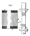
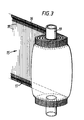
- the filter coalescer comprises a casing 1 enclosing a cartridge 2.
- the casing is fitted with an entrance 3, a drain or lower offtake 4, several level-controlled offtakes 5, an upper offtake 6 and a relief 7.
- a spigot 8 is fitted in the entrance 3 to locate and support the cartridge 2.
- the cartridge comprises a fixed lower plate 9 attached to a fixed lower collar 10, the plate 9 resting on the spigot 8, and a movable upper collar 11 slidably mounted on a perforated inner cylinder 12 open at its lower end and closed at its upper end.
- the upper collar 11 is affixed to a "top hat” 13 which is connected to an actuating rod 13a to which rotational and longitudinal motion is imparted by a mechanism outside the filter coalescer (not shown, possibly a hand wheel).
- the cartridge comprises a perforated outer cylinder 14 which provides a guide for the collar 11 and also restrains the fibres when compressed.
- a filter coalescer element 15 composed of polyacrylate fibres contains top and bottom woven edges 16 and 17 and only cross threads 18 in between.
- the element 15 is wound round the inner cylinder 14 and the upper edge 16 is clamped to the upper collar 11 and the lower edge 17 to the lower collar 10 by means of clamps (not shown).
- the woven edges 16 and 17 may be coated with adhesive and then wound on to an element 19 held in a jig and rotated by a motor to form the cartridge 2.
- Figure 1 shows the cartridge in its compact operating position in which the fibres would be twisted and compressed.
- the actuating rod 13a is actuated and the upper collar 11 is moved upwardly and away from the lower collar 10 and rotated so that the fibres 18 are straightened, separated and extended.
- the cartridge is then flushed with wash water.
- the cartridge was of the type described with reference to Figures 1 and 2 of the drawings, with steel end collars.
- the filter element contained 2,870 strands of Nylon 66, 20 u in diameter and 21 cm in length.
- the diameter of the outer permeable cylinder was 12.5 cm and the inner 10.0 cm.
- the feed was North Sea water containing a planktonic bloom. Over the duration of the test this varied in its particulate composition according to the following analysis.
- the feed was passed through the cartridge of a flow rate of 12 1/min unless indicated otherwise.
- the bed length and extent of rotation was varied as shown in the following Table.
- a similar cartridge was used to remove water from wet crude oil by coalescence.
- the relaxed length of the filter element was 25 cm and it was used simultaneously compressed to a length of 19.0 cm and twisted through 180°.
- the crude oil was derived from the Egmanton oilfield, Nottingham.
- a demulsifier sold under the Trade Name Petrolite DS 964 was added in a concentration of 10 ppm to aid coalescence,
Landscapes
- Chemical & Material Sciences (AREA)
- Chemical Kinetics & Catalysis (AREA)
- Engineering & Computer Science (AREA)
- Water Supply & Treatment (AREA)
- Physics & Mathematics (AREA)
- Thermal Sciences (AREA)
- Filtering Materials (AREA)
- Filtration Of Liquid (AREA)
- Treatment Of Liquids With Adsorbents In General (AREA)
- Water Treatment By Sorption (AREA)
Applications Claiming Priority (2)
| Application Number | Priority Date | Filing Date | Title |
|---|---|---|---|
| GB8517145 | 1985-07-05 | ||
| GB858517145A GB8517145D0 (en) | 1985-07-05 | 1985-07-05 | Expandable bed fibre filter & coalescer |
Publications (3)
| Publication Number | Publication Date |
|---|---|
| EP0207797A2 true EP0207797A2 (fr) | 1987-01-07 |
| EP0207797A3 EP0207797A3 (en) | 1989-04-26 |
| EP0207797B1 EP0207797B1 (fr) | 1991-01-30 |
Family
ID=10581897
Family Applications (1)
| Application Number | Title | Priority Date | Filing Date |
|---|---|---|---|
| EP19860305176 Expired EP0207797B1 (fr) | 1985-07-05 | 1986-07-03 | Filtre à lit de fibres expansibles et appareil de coalescence |
Country Status (7)
| Country | Link |
|---|---|
| EP (1) | EP0207797B1 (fr) |
| AU (1) | AU590291B2 (fr) |
| CA (1) | CA1297424C (fr) |
| DE (1) | DE3677269D1 (fr) |
| GB (1) | GB8517145D0 (fr) |
| HK (1) | HK39194A (fr) |
| NO (1) | NO167848C (fr) |
Cited By (17)
| Publication number | Priority date | Publication date | Assignee | Title |
|---|---|---|---|---|
| DE8814236U1 (de) * | 1988-11-14 | 1989-02-23 | Franken Filtertechnik oHG, 5030 Hürth | Phasentrennelement |
| EP0366362A1 (fr) * | 1988-10-26 | 1990-05-02 | Kaldair International Limited | Appareil de filtration et de coalescence de liquides |
| EP0389346A1 (fr) * | 1989-03-24 | 1990-09-26 | Total Raffinage Distribution S.A. | Dispositif de séparation de deux liquides non miscibles et application de ce dispositif au dessalage d'une charge hydrocarbonée |
| EP0494800A3 (fr) * | 1991-01-10 | 1994-01-26 | Capital Formation Inc | |
| US5318704A (en) * | 1988-09-22 | 1994-06-07 | Kalsep Limited | Apparatus for filtering and coalescing liquids |
| US5527462A (en) * | 1994-11-15 | 1996-06-18 | Delaware Capital Formation, Inc. | Filter with axially movable wiper |
| EP0725040A1 (fr) * | 1994-06-20 | 1996-08-07 | Passavant-Werke Ag | Séparateur de coalescence |
| WO1996024428A1 (fr) * | 1995-02-10 | 1996-08-15 | Kalsep Limited | Procede de fabrication d'un element filtrant fibreux |
| US5569383A (en) * | 1994-12-15 | 1996-10-29 | Delaware Capital Formation, Inc. | Filter with axially and rotatably movable wiper |
| RU2129899C1 (ru) * | 1998-01-13 | 1999-05-10 | Гринь Александр Владимирович | Устройство для разделения дисперсных смесей, содержащих нефтепродукты |
| US7282155B2 (en) | 2000-09-19 | 2007-10-16 | Fibra Limited | Device and a method for filtering a fluid |
| WO2008156537A1 (fr) * | 2007-06-14 | 2008-12-24 | Merichem Company | Procédé de séparation perfectionné |
| US8308957B2 (en) | 2007-06-14 | 2012-11-13 | Merichem Company | Process for separating mercaptans from caustic |
| WO2013083365A1 (fr) * | 2011-12-09 | 2013-06-13 | Mann+Hummel Gmbh | Filtre à carburant d'un moteur à combustion interne et élément filtrant d'un filtre à carburant |
| US10842332B2 (en) | 2015-07-01 | 2020-11-24 | Dyson Technology Limited | Separating apparatus |
| US10953359B2 (en) | 2015-07-01 | 2021-03-23 | Dyson Technology Limited | Separating apparatus |
| CN114618206A (zh) * | 2021-04-01 | 2022-06-14 | 上海宏跞新材料科技有限公司 | 一种用于固液分离的cxm精密高效过滤器 |
Families Citing this family (1)
| Publication number | Priority date | Publication date | Assignee | Title |
|---|---|---|---|---|
| DE4103164C2 (de) * | 1991-02-02 | 2001-02-08 | Ifg Ingenieur Und Forschungsge | Verfahren zum Reinigen von Sink- und Schwimmstoffe enthaltenden Abwässern |
Family Cites Families (4)
| Publication number | Priority date | Publication date | Assignee | Title |
|---|---|---|---|---|
| EP0004724B1 (fr) * | 1978-04-05 | 1981-10-28 | The British Petroleum Company p.l.c. | Procédé et appareil de coalescence et produits purifiés ainsi obtenus |
| AT365474B (de) * | 1979-05-28 | 1982-01-25 | Zhdanovskij Metall Inst | Filter |
| CH641969A5 (en) * | 1979-05-29 | 1984-03-30 | Zhdanovskij Metall Inst | Filter and use of the filter |
| CA1170195A (fr) * | 1981-01-21 | 1984-07-03 | Denis S. Ward | Cartouche filtrante |
-
1985
- 1985-07-05 GB GB858517145A patent/GB8517145D0/en active Pending
-
1986
- 1986-07-01 AU AU59432/86A patent/AU590291B2/en not_active Ceased
- 1986-07-02 CA CA000512934A patent/CA1297424C/fr not_active Expired - Fee Related
- 1986-07-03 EP EP19860305176 patent/EP0207797B1/fr not_active Expired
- 1986-07-03 NO NO862695A patent/NO167848C/no unknown
- 1986-07-03 DE DE8686305176T patent/DE3677269D1/de not_active Expired - Fee Related
-
1994
- 1994-04-28 HK HK39194A patent/HK39194A/en not_active IP Right Cessation
Cited By (28)
| Publication number | Priority date | Publication date | Assignee | Title |
|---|---|---|---|---|
| EP0360601B1 (fr) * | 1988-09-22 | 1998-03-25 | Kalsep Limited | Appareil de filtration et de coalescence pour liquides |
| US5318704A (en) * | 1988-09-22 | 1994-06-07 | Kalsep Limited | Apparatus for filtering and coalescing liquids |
| EP0366362A1 (fr) * | 1988-10-26 | 1990-05-02 | Kaldair International Limited | Appareil de filtration et de coalescence de liquides |
| WO1990004443A1 (fr) * | 1988-10-26 | 1990-05-03 | Kaldair International Limited | Appareil a filtre et liquides de coalescence |
| DE8814236U1 (de) * | 1988-11-14 | 1989-02-23 | Franken Filtertechnik oHG, 5030 Hürth | Phasentrennelement |
| EP0389346A1 (fr) * | 1989-03-24 | 1990-09-26 | Total Raffinage Distribution S.A. | Dispositif de séparation de deux liquides non miscibles et application de ce dispositif au dessalage d'une charge hydrocarbonée |
| FR2644708A1 (fr) * | 1989-03-24 | 1990-09-28 | Total France | Dispositif de separation de deux liquides non miscibles et application de ce dispositif |
| US5017294A (en) * | 1989-03-24 | 1991-05-21 | Compagnie De Raffinage Et De Distribution Total France | Apparatus for the separation of two immiscible liquids and use of said apparatus in the desalting of a hydrocarbon feedstock |
| EP0494800A3 (fr) * | 1991-01-10 | 1994-01-26 | Capital Formation Inc | |
| EP0725040A1 (fr) * | 1994-06-20 | 1996-08-07 | Passavant-Werke Ag | Séparateur de coalescence |
| US5527462A (en) * | 1994-11-15 | 1996-06-18 | Delaware Capital Formation, Inc. | Filter with axially movable wiper |
| US5569383A (en) * | 1994-12-15 | 1996-10-29 | Delaware Capital Formation, Inc. | Filter with axially and rotatably movable wiper |
| WO1996024428A1 (fr) * | 1995-02-10 | 1996-08-15 | Kalsep Limited | Procede de fabrication d'un element filtrant fibreux |
| AU698208B2 (en) * | 1995-02-10 | 1998-10-29 | Kalsep Limited | Method of forming a fibrous filter element |
| RU2129899C1 (ru) * | 1998-01-13 | 1999-05-10 | Гринь Александр Владимирович | Устройство для разделения дисперсных смесей, содержащих нефтепродукты |
| US7282155B2 (en) | 2000-09-19 | 2007-10-16 | Fibra Limited | Device and a method for filtering a fluid |
| WO2008156537A1 (fr) * | 2007-06-14 | 2008-12-24 | Merichem Company | Procédé de séparation perfectionné |
| US7833499B2 (en) | 2007-06-14 | 2010-11-16 | Merichem Company | Separation process |
| RU2441688C2 (ru) * | 2007-06-14 | 2012-02-10 | Меричем Компани | Способ разделения по меньшей мере двух несмешивающихся жидкостей и его применение |
| CN101815565B (zh) * | 2007-06-14 | 2012-07-04 | 梅里凯姆公司 | 改进的分离方法 |
| US8308957B2 (en) | 2007-06-14 | 2012-11-13 | Merichem Company | Process for separating mercaptans from caustic |
| US8454824B2 (en) | 2007-06-14 | 2013-06-04 | Merichem Company | Single vertical tower for treating a stream of rich caustic containing mercaptan compounds |
| WO2013083365A1 (fr) * | 2011-12-09 | 2013-06-13 | Mann+Hummel Gmbh | Filtre à carburant d'un moteur à combustion interne et élément filtrant d'un filtre à carburant |
| CN103958019A (zh) * | 2011-12-09 | 2014-07-30 | 曼·胡默尔有限公司 | 内燃机的燃油滤清器和燃油滤清器的过滤元件 |
| US10842332B2 (en) | 2015-07-01 | 2020-11-24 | Dyson Technology Limited | Separating apparatus |
| US10953359B2 (en) | 2015-07-01 | 2021-03-23 | Dyson Technology Limited | Separating apparatus |
| CN114618206A (zh) * | 2021-04-01 | 2022-06-14 | 上海宏跞新材料科技有限公司 | 一种用于固液分离的cxm精密高效过滤器 |
| CN114618206B (zh) * | 2021-04-01 | 2024-06-04 | 上海宏跞新材料科技有限公司 | 一种用于固液分离的cxm精密高效过滤器 |
Also Published As
| Publication number | Publication date |
|---|---|
| EP0207797A3 (en) | 1989-04-26 |
| AU5943286A (en) | 1987-01-08 |
| EP0207797B1 (fr) | 1991-01-30 |
| NO167848B (no) | 1991-09-09 |
| DE3677269D1 (de) | 1991-03-07 |
| GB8517145D0 (en) | 1985-08-14 |
| NO862695D0 (no) | 1986-07-03 |
| NO862695L (no) | 1987-01-06 |
| NO167848C (no) | 1991-12-18 |
| HK39194A (en) | 1994-05-06 |
| AU590291B2 (en) | 1989-11-02 |
| CA1297424C (fr) | 1992-03-17 |
Similar Documents
| Publication | Publication Date | Title |
|---|---|---|
| US5174907A (en) | Method of filtering using an expandable bed fiber and coalescer | |
| EP0207797B1 (fr) | Filtre à lit de fibres expansibles et appareil de coalescence | |
| US5439588A (en) | Coalescing filter using an expandable bed fiber | |
| CA1170195A (fr) | Cartouche filtrante | |
| US3450632A (en) | Method for simultaneously coalescing,filtering and removing oil traces from liquids and media for accomplishing the same | |
| US4058463A (en) | Element for filtering and separating fluid mixtures | |
| DE69017639T2 (de) | Reinigung von Druckluft-Kondensat. | |
| US5112479A (en) | Oil purification unit with cyclonic reservoir section and filtration section | |
| US3352778A (en) | Shaped fibers | |
| US5478484A (en) | Apparatus and method including a hydrocyclone separator in combination with a tubular filter | |
| US3733267A (en) | Process of filtration of dry cleaning fluid | |
| US3186551A (en) | Jet fuel filtering, emulsion breaking and drying device | |
| US2739713A (en) | Cartridge for removing undesirable free water and solid contaminant from liquid hydrocarbon | |
| US3558482A (en) | Water purification | |
| US3797666A (en) | Apparatus for separating fine oil droplets and sludge suspended in liquid | |
| CA1112583A (fr) | Dispositif separateur | |
| US3519560A (en) | Method and apparatus for removing water from fluids | |
| US4328098A (en) | Filter apparatus | |
| US4512890A (en) | Means for the sorption of a petroleum product from a liquid | |
| EP0678477A1 (fr) | Procédé et dispositif pour l'épuration de liquides aqueux contenant des matières particulaires et du liquide organique immiscible à l'eau | |
| DE2519959A1 (de) | Vorrichtung zur oel-wasser-trennung | |
| US20160297688A1 (en) | System and method for removing solids and hydrocarbons from water | |
| AT392632B (de) | Verfahren zur entfernung und rueckgewinnung von ungeloesten organischen stoffen und gegebenenfalls vorliegenden, geloesten organischen stoffen aus wasser | |
| US5190662A (en) | Removal of iron sulfide particles from alkanolamine solutions | |
| US6015502A (en) | Reversing flow coalescing system |
Legal Events
| Date | Code | Title | Description |
|---|---|---|---|
| PUAI | Public reference made under article 153(3) epc to a published international application that has entered the european phase |
Free format text: ORIGINAL CODE: 0009012 |
|
| AK | Designated contracting states |
Kind code of ref document: A2 Designated state(s): BE DE FR GB IT NL |
|
| PUAL | Search report despatched |
Free format text: ORIGINAL CODE: 0009013 |
|
| AK | Designated contracting states |
Kind code of ref document: A3 Designated state(s): BE DE FR GB IT NL |
|
| RHK1 | Main classification (correction) |
Ipc: B01D 17/022 |
|
| 17P | Request for examination filed |
Effective date: 19890519 |
|
| 17Q | First examination report despatched |
Effective date: 19900430 |
|
| GRAA | (expected) grant |
Free format text: ORIGINAL CODE: 0009210 |
|
| AK | Designated contracting states |
Kind code of ref document: B1 Designated state(s): BE DE FR GB IT NL |
|
| ITF | It: translation for a ep patent filed | ||
| REF | Corresponds to: |
Ref document number: 3677269 Country of ref document: DE Date of ref document: 19910307 |
|
| ET | Fr: translation filed | ||
| PLBE | No opposition filed within time limit |
Free format text: ORIGINAL CODE: 0009261 |
|
| STAA | Information on the status of an ep patent application or granted ep patent |
Free format text: STATUS: NO OPPOSITION FILED WITHIN TIME LIMIT |
|
| 26N | No opposition filed | ||
| ITPR | It: changes in ownership of a european patent |
Owner name: CESSIONE;KALSEP LIMITED |
|
| REG | Reference to a national code |
Ref country code: FR Ref legal event code: TP |
|
| NLS | Nl: assignments of ep-patents |
Owner name: KALSEP LIMITED TE CAMBERLEY, GROOT-BRITTANNIE. |
|
| BECA | Be: change of holder's address |
Free format text: 930811 *KALSEP LTD:DOMAN ROAD YORKTOWN INDUSTRIAL ESTATE, CAMBERLEY SURREY GU15 3DF |
|
| REG | Reference to a national code |
Ref country code: GB Ref legal event code: 732E |
|
| REG | Reference to a national code |
Ref country code: GB Ref legal event code: IF02 |
|
| PGFP | Annual fee paid to national office [announced via postgrant information from national office to epo] |
Ref country code: GB Payment date: 20020724 Year of fee payment: 17 |
|
| PGFP | Annual fee paid to national office [announced via postgrant information from national office to epo] |
Ref country code: FR Payment date: 20020726 Year of fee payment: 17 |
|
| PGFP | Annual fee paid to national office [announced via postgrant information from national office to epo] |
Ref country code: NL Payment date: 20020730 Year of fee payment: 17 |
|
| PGFP | Annual fee paid to national office [announced via postgrant information from national office to epo] |
Ref country code: DE Payment date: 20020731 Year of fee payment: 17 |
|
| PGFP | Annual fee paid to national office [announced via postgrant information from national office to epo] |
Ref country code: BE Payment date: 20020919 Year of fee payment: 17 |
|
| PG25 | Lapsed in a contracting state [announced via postgrant information from national office to epo] |
Ref country code: GB Free format text: LAPSE BECAUSE OF NON-PAYMENT OF DUE FEES Effective date: 20030703 |
|
| PG25 | Lapsed in a contracting state [announced via postgrant information from national office to epo] |
Ref country code: BE Free format text: LAPSE BECAUSE OF NON-PAYMENT OF DUE FEES Effective date: 20030731 |
|
| BERE | Be: lapsed |
Owner name: *KALSEP LTD Effective date: 20030731 |
|
| PG25 | Lapsed in a contracting state [announced via postgrant information from national office to epo] |
Ref country code: NL Free format text: LAPSE BECAUSE OF NON-PAYMENT OF DUE FEES Effective date: 20040201 |
|
| PG25 | Lapsed in a contracting state [announced via postgrant information from national office to epo] |
Ref country code: DE Free format text: LAPSE BECAUSE OF NON-PAYMENT OF DUE FEES Effective date: 20040203 |
|
| GBPC | Gb: european patent ceased through non-payment of renewal fee |
Effective date: 20030703 |
|
| PG25 | Lapsed in a contracting state [announced via postgrant information from national office to epo] |
Ref country code: FR Free format text: LAPSE BECAUSE OF NON-PAYMENT OF DUE FEES Effective date: 20040331 |
|
| NLV4 | Nl: lapsed or anulled due to non-payment of the annual fee |
Effective date: 20040201 |
|
| REG | Reference to a national code |
Ref country code: FR Ref legal event code: ST |
|
| PG25 | Lapsed in a contracting state [announced via postgrant information from national office to epo] |
Ref country code: IT Free format text: LAPSE BECAUSE OF NON-PAYMENT OF DUE FEES Effective date: 20050703 |