EP0208007A1 - Gerät zur Messung der psycho-physiologischen Verfassung - Google Patents
Gerät zur Messung der psycho-physiologischen Verfassung Download PDFInfo
- Publication number
- EP0208007A1 EP0208007A1 EP85108458A EP85108458A EP0208007A1 EP 0208007 A1 EP0208007 A1 EP 0208007A1 EP 85108458 A EP85108458 A EP 85108458A EP 85108458 A EP85108458 A EP 85108458A EP 0208007 A1 EP0208007 A1 EP 0208007A1
- Authority
- EP
- European Patent Office
- Prior art keywords
- subject
- actual
- condition
- determining
- coupled
- Prior art date
- Legal status (The legal status is an assumption and is not a legal conclusion. Google has not performed a legal analysis and makes no representation as to the accuracy of the status listed.)
- Withdrawn
Links
- 230000003304 psychophysiological effect Effects 0.000 title claims abstract description 12
- 230000002996 emotional effect Effects 0.000 claims abstract description 31
- 230000003340 mental effect Effects 0.000 claims abstract description 30
- 230000004044 response Effects 0.000 claims abstract description 14
- 230000004913 activation Effects 0.000 claims abstract description 8
- 230000005236 sound signal Effects 0.000 claims abstract description 7
- 238000000034 method Methods 0.000 claims description 19
- 230000015654 memory Effects 0.000 claims description 15
- 230000001105 regulatory effect Effects 0.000 claims description 13
- 238000012549 training Methods 0.000 claims description 12
- 230000000903 blocking effect Effects 0.000 claims description 10
- 230000007423 decrease Effects 0.000 claims description 8
- 230000035484 reaction time Effects 0.000 claims description 8
- 238000005070 sampling Methods 0.000 claims description 8
- 230000004907 flux Effects 0.000 claims description 4
- 230000008859 change Effects 0.000 claims description 3
- 230000000694 effects Effects 0.000 claims description 3
- 230000003213 activating effect Effects 0.000 claims description 2
- 230000006870 function Effects 0.000 claims description 2
- 230000001939 inductive effect Effects 0.000 claims description 2
- 230000003252 repetitive effect Effects 0.000 claims description 2
- 238000004904 shortening Methods 0.000 claims description 2
- 230000001960 triggered effect Effects 0.000 claims description 2
- 238000001994 activation Methods 0.000 claims 4
- 230000008878 coupling Effects 0.000 claims 1
- 238000010168 coupling process Methods 0.000 claims 1
- 238000005859 coupling reaction Methods 0.000 claims 1
- 238000005259 measurement Methods 0.000 description 27
- 238000012360 testing method Methods 0.000 description 26
- 210000003811 finger Anatomy 0.000 description 12
- 238000010586 diagram Methods 0.000 description 9
- 230000001965 increasing effect Effects 0.000 description 6
- 238000013461 design Methods 0.000 description 5
- 230000008901 benefit Effects 0.000 description 4
- 230000014509 gene expression Effects 0.000 description 4
- 230000003247 decreasing effect Effects 0.000 description 3
- 230000001419 dependent effect Effects 0.000 description 3
- 230000002349 favourable effect Effects 0.000 description 3
- 238000009532 heart rate measurement Methods 0.000 description 3
- 230000010365 information processing Effects 0.000 description 3
- 230000003287 optical effect Effects 0.000 description 3
- 230000010287 polarization Effects 0.000 description 3
- 230000035945 sensitivity Effects 0.000 description 3
- 230000000007 visual effect Effects 0.000 description 3
- 238000004364 calculation method Methods 0.000 description 2
- 230000000737 periodic effect Effects 0.000 description 2
- 238000012545 processing Methods 0.000 description 2
- 230000010349 pulsation Effects 0.000 description 2
- 238000012797 qualification Methods 0.000 description 2
- 230000001133 acceleration Effects 0.000 description 1
- 239000008280 blood Substances 0.000 description 1
- 210000004369 blood Anatomy 0.000 description 1
- 230000036760 body temperature Effects 0.000 description 1
- 238000010276 construction Methods 0.000 description 1
- 230000001934 delay Effects 0.000 description 1
- 238000001514 detection method Methods 0.000 description 1
- 238000011156 evaluation Methods 0.000 description 1
- 210000004247 hand Anatomy 0.000 description 1
- 230000001976 improved effect Effects 0.000 description 1
- 230000007246 mechanism Effects 0.000 description 1
- 238000010606 normalization Methods 0.000 description 1
- 210000000056 organ Anatomy 0.000 description 1
- 230000008520 organization Effects 0.000 description 1
- 230000008569 process Effects 0.000 description 1
- 230000002441 reversible effect Effects 0.000 description 1
- 238000001228 spectrum Methods 0.000 description 1
- 238000010183 spectrum analysis Methods 0.000 description 1
- 230000000638 stimulation Effects 0.000 description 1
- 230000003797 telogen phase Effects 0.000 description 1
- 210000003813 thumb Anatomy 0.000 description 1
- 238000012800 visualization Methods 0.000 description 1
Images




Classifications
-
- A—HUMAN NECESSITIES
- A61—MEDICAL OR VETERINARY SCIENCE; HYGIENE
- A61B—DIAGNOSIS; SURGERY; IDENTIFICATION
- A61B5/00—Measuring for diagnostic purposes; Identification of persons
- A61B5/16—Devices for psychotechnics; Testing reaction times ; Devices for evaluating the psychological state
-
- A—HUMAN NECESSITIES
- A61—MEDICAL OR VETERINARY SCIENCE; HYGIENE
- A61B—DIAGNOSIS; SURGERY; IDENTIFICATION
- A61B5/00—Measuring for diagnostic purposes; Identification of persons
- A61B5/02—Detecting, measuring or recording for evaluating the cardiovascular system, e.g. pulse, heart rate, blood pressure or blood flow
-
- A—HUMAN NECESSITIES
- A61—MEDICAL OR VETERINARY SCIENCE; HYGIENE
- A61B—DIAGNOSIS; SURGERY; IDENTIFICATION
- A61B5/00—Measuring for diagnostic purposes; Identification of persons
- A61B5/05—Detecting, measuring or recording for diagnosis by means of electric currents or magnetic fields; Measuring using microwaves or radio waves
- A61B5/053—Measuring electrical impedance or conductance of a portion of the body
- A61B5/0531—Measuring skin impedance
-
- A—HUMAN NECESSITIES
- A61—MEDICAL OR VETERINARY SCIENCE; HYGIENE
- A61B—DIAGNOSIS; SURGERY; IDENTIFICATION
- A61B5/00—Measuring for diagnostic purposes; Identification of persons
- A61B5/48—Other medical applications
- A61B5/486—Biofeedback
Definitions
- the invention relates to the field of biophysical examinations, more particularly to a method and apparatus for measuring the actual psychophysiological condition of a subject.
- psychophysiological condition the complexity of the actual emotional, mental and physical conditions is understood.
- the measurement of the emotional condition is generally related to skin conductance measurements. Although there are several ways for measuring the skin conductance, they all have some disadvantages.
- the main problem lies in that direct current sensors are generally not usable, because the direct current flowing through a portion of the human body tends to cause polarization phenomena in the particular body area which can falsify the result.
- alternating signals are used for skin conductance detection.
- the processing of AC voltages has its own drawbacks which lie mostly in the reduced sensitivity.
- the heart rate of a subject is often measured. Such measurements are made generally by means of pulse sensors including a light emitting diode and a light sensitive transistor arranged to give place for a finger therebetween.
- pulse sensors including a light emitting diode and a light sensitive transistor arranged to give place for a finger therebetween.
- a further object of the invention lies in providing an improved apparatus for detecting skin conductance, which can highly facilitate the emotional condition measurements.
- a still further object of the invention lies in providing a novel circuit arrangement for heart rate measurements which can provide a uniform detecting sensitivity even if the hand is moved, whereby the physical condition tests are facilitated.
- an apparatus for measuring the actual psychophysiological condition of a subject which comprises:
- a method for determining the cathegory level of the actual emotional condition of the subject comprises the steps of inducing the subject to perform an autogen training based on a biofeedback in which he or she already has at least some experience in a first phase for a predetermined time counted from a starting moment, recording a representation of the feedback value in said starting moment, giving a task for the subject that in the first phase a relaxed condition should be reached, recording the actual value of the feedback representation in the ending moment of the first phase, carrying out the autogen training in a second phase immediately following the first phase for a second predetermined time, in which giving a task for the subject to reach an active condition, recording the feedback representation in the end moment of the second phase, and determining the cathegory level on the basis of a linear combination of the relative changes of the recorded feedback representations during the phases.
- a method has been provided to determine the actual mental condition of a subject, comprising the steps of providing a random sequence of a predetermined number of light signals for the subject, in which the light signals are allocated to a predetermined number of display segments in a random distribution with uniform probability of activating any of the segments, these segments have identical shapes and each of them is associated with respective keys, instructing the subject to push the key associated with the flashing one of the segments when the flashing is percepted, providing acoustical signals together with selected ones of the light signals according to a random selection, instructing the subject not to push any key when an acoustic signal is perceived, measuring the sum of reaction times defined between the moments of the establishments of the light signals and the moments of pushing the associated key, measuring the numer of right pushing movements and the number of effective acoustic blockings, and the mental condition is cathegorized according to the relation of a weighted sum of the three measured values to predetermined treshold values.
- a method for determining the cathegory level of the physical condition of a subject comprising the steps of instructing the subject to perform a repetitive sequence of predetermined gymnastical excercises which impose a physical load, sensing the occurrence of each excercise, detecting the heart rate of the subject, recording the heart rate in the end moment of said sequence, instructing the subject following the end moment to relax for a predetermined time, recording the heart rate value in the end moment of the relaxation period, and providing the weighted sum of the efficiency of the accomplishment of the excercises, of the first recorded heart rate, and of the relative decrease of the heart rate during the relaxation period to define a value characteristic to the actual level of the physical condition.
- a circuit arrangement for measuring the skin conductance, comprising a pair of sensors engaging a body surface, a resistor with known resistance, a switching means for applying a constant direct voltage alternatively on the sensor or on the resistor, a measuring means for determining the current flowing through the sensors and through the resistor under the effect of the voltage, and evaluating means connected to the measuring means, which on the basis of the known resistance value and of the measured current values provides the representation of the conductance defined between the sensors.
- a circuit arrangement for measuring the heart rate of a subject comprising: a pulse sensor, including a light emitting diode and a light sensitive transistor with current depending on an incident light flux from the light of the diode following passage through a finger of the subject; a means for determining the current flowing through the diode; a current generator coupled in series with the light sensitive transistor; a regulating means with an input controlled by the difference of the current flowing through the transistor and the current of the current generator, the regulating means has integrating properties with a time constant of about 1 to 2 s, the output of the regulating means is coupled to the current determining means to adjust the current thereof.
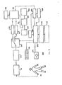
- FIG. 1 shows a simplified perspective view of an embodiment of the apparatus according to the present invention.
- the apparatus comprises a small compact case 10, which, during operation can and should be held in hand.
- recesses are made for accomodating the fingers, of which recesses 12, 14, 16 and 18 are shown in FIG. 1.
- a recess for the thumb is made in the other side of the case 10. :
- a pulse sensor 20 is arranged in one of the recesses 14 whereas sensors 22, 24 for skin conductance measurements are arranged in the two neighbouring recesses 16 and 18.
- a pair of zones 26 and 28 of equal design are provided one beneath the other on the front face of the case 10 and each of them is split up into four parts.
- Four identical keys 30, 32 and 36 are arranged in the lower zone 26 which can be actuated separately.
- the upper zone 28 comprises four identical display segments 38, 40, 42 and 44.
- An appropriate socket is arranged in the upper wall of the case 10 for the connection of a head-phone 46.
- the other handling means are not shown in FIG. 1. It is preferable if the various handling organs are arranged elsewhere than the face plate in order that their presence can not disturb the functional relationship between the fields in the zones 26 and 28.
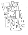
- FIG. 2 shows the overall block diagram of the apparatus shown in FIG. 1.
- the main part of the apparatus is formed by a central control and calculating block 50 which can be divided in three main functional units i.e. emotional condition examining unit 100, mental condition examining unit 200 and physical condition examining unit 300.
- the central control and calculating I block 50 can be implemented by a programmed microprocessor.
- a pulse rate measuring block 52 and a skin conductance measuring block 60 are coupled to the central control and calculating block 50, and respective inputs of these blocks 52 and 60 are coupled to the pulse sensor 20 and to the sensors 22 and 24.
- a display 56 comprising the display segments 38 to 44 in the zone 28 is also coupled to the central control nad calculating block 50.
- the head-phone 46 is connected through an acoustic coupler 58 to the central control and calculating block 50.
- FIG. 3 shows the functional block diagram of the emotional condition examining unit 100.
- a biological feedback system has been provided for the subject to be examined, which enables practicing an autogen training by which the subject reaches a rest condition following an active starting state and a further active state from the rest condition.
- Such kind of autogen training can utilize the feedback of the relative activity of the alpha waves in the EEG spectrum, the feedback of the skin conductance or in given cases the feedback of the body temperature. From the point of view of the constructional design of the biofeedback system, of its handling facilities and of the efficiency, duration and feasibility for learning of the autogen training, it is believed that the feedback of the skin conductance can be considered to be the most preferable of all possible other kinds of feedback, therefore FIG. 3 shows the unit 100 as based on skin conductance feedback.
- the subject under examination holds the apparatus shown in FIG. 1 in one of his or her hands, and his or her fingers touch the sensors 22, 24, and a skin conductance measuring block 60 measures the skin conductance.
- the output of the skin conductance measuring block 60 supplies the skin conductance level referred to hereinafter as SCL, and this output is coupled to input of a sample and hold circuit 102, to input of a divider 104 and to input of a multi-position controlled switch 106.
- the output of the divider 104 is connected to the acoustic coupler 58 which latter is coupled to the head--phone 46. It is preferable, if the output of the divider 104 which delivers a digital value representing the frequency of the audio signal is coupled also to the display 54 for digitally displaying this value.
- the divider 104 has a second input coupled to the output of the sample and hold circuit 102 to receive the digital value of the sampled SCL signal.
- control unit 108 having respective outputs coupled through line 110 to an input of the sample and hold circuit 102 which determines the sampling moment, through line 112 to control input of the controlled switch 106 and through line 114 to starting input of a first timer 116.
- the controlled switch 106 has three outputs coupled to respective inputs of first, second and third sample and store circuits 118, 120 and 122, and the outputs of these circuits are coupled to inputs of an arithmetical and logical unit 124.
- a further input of the arithmetical and logical unit 124 is connected to a constant memory 126 which stores the constant values required for the calculations.
- the output of the arithmetical and logical unit 124 is connected to a first input of a digital comparator 128 which has a second input coupled to a second constant memory 130 which stores treshold values required for the comparison.
- the output of the digital comparator 128 is coupled to display 56a which can be formed by any of the display segments 38 to 44.
- the control unit 108 is connected also to a second timer 134 started by the output of the first timer 116.
- a start key 132 for starting the operation of the emotional condition examining unit 100 which can be formed by any of the keys 30 to 36.
- the determination of the actual emotional condition is carried out as follows.
- the sample and hold circuit 102 receives a sampling command through the line 110 from the control unit 108, and stores the starting SCL value (moment t 0 in FIG. 8) supplied by the output of the skin conductance measuring block 60.
- the two inputs of the divider 104 there is the same digital number and their quotient is therefore unity.
- the input of the acoustic coupler 58 receives a digital number associated with a basic audio frequency which can be e.g. 300 Hz. Owing to the division and the normalization in the starting moments of each test,the same basic frequency can be heard in the head-phone 46 which is independent of the actual SCL value.
- the divider 104 delivers a digital number representing the quotient of the actual SCL value and the starting SCL 1 value, and this number will set the acoustic coupler 5S to generate a lower tone.
- a decrease in the SCL value e.g. by 10 % compared to the starting value results in the decrease of the starting audio frequency of 300 Hz by 30 Hz.
- the subject During this phase of the autogen training the subject has the task of deepening the audio frequency with all effort.
- the digital value of the actual frequency can even be displayed on the display 56.
- the starting SCL 1 value will be stored in the moment t o not only in the sample and hold circuit 102, but through the controlled switch 106 also in the first sample and store circuit 118. Also in the starting moment to the first timer 116 will be started through the line 114 to provide a predetermined timing Tl e.g. between 1 and 5 minutes.
- FIG. 8 shows the time diagram of the SCL value.
- the first timer 116 delivers a signal for the control unit 108 and the relaxation phase is finished.
- the control unit 108 sets the controlled switch 106 in a further position and in this moment t i the actual SCL 2 value will be read in the second sample and store circuit 120. Simultaneously the sample and hold circuit 102 receives through the line 110 a new sampling command and the SCL 2 value will be held therein.
- the two inputs of the divider 104 will be again identical, and the tone will take the starting frequency, i.e. 300 Hz.
- This change indicates for the subject the end of the relaxation phase. This indication can be underlined e.g. by flashing a digit on the display 56.
- the first timer 116 starts the timing of the second timer 134 which has preferably the same timing duration.
- the subject under test knows that after the end of the relaxation phase the task will be changed and the active condition should be regained as soon as possible that is the autogen training should be practiced in reverse direction. The subject strives to increase and not to decrease the tone pitch, whereby the skin conductivity will also increase.
- the control unit 108 sets the controlled switch 106 in a further position, and the third sample and store circuit 122 will store the actual SCL 3 value. Now the emotional condition examination test is finished and the subject is informed thereabout by means of the display 56.
- the emotional condition depends on the extent of contribution of the subject in carrying out the relaxation and later the activation tasks.
- the emotional condition is favourable if this contribution was successiveful, and it is not favourable if it was not.
- the apparatus according to the invention is capable of delivering the value S 1 directly, in the practice, however, it is sufficient to know whether the actual emotional condition is high, medium or low.
- the constant memory 130 stores two treshold constants K 11 and K 12 with which the value S 1 will be compared in the digital comparator 128.
- the emotional condition is favourable, i.e. high, if the value S 1 falls between the two constants K 11 and K 12 , the emotional condition is on medium level, and the emotional condition is low, if S 1 is smaller than the constant K 12 .
- the display 56a shows an indication corresponding to these three possible states.
- the emotional condition can be examined not only by the unit 100 shown in FIG. 3 but by a number of alternative arrangements. From the aspect of the present invention it has an importance only that the level of the emotional condition is defined as the efficiency of an autogen training comprising a first phase directed to reach a relaxed state in a prescribed time and a second phase for reaching an active condition again.
- FIG. 6 in which a preferable embodiment of the skin conductance measuring block 60 is shown, since this embodiment is believed to can measure the SCL value easier and with a higher accuracy than the conventionally used SCL meters.
- a transistor Tl is shown with an emitter circuit comprising alternatively controlled switches SS1 and SS2, by which the SCL sensors 22, 24 or a resistor R N are coupled to the emitter.
- the transistor Tl has a base circuit comprising resistors Rl, R2 and a diode D for compensating temperature dependency.
- the so cnnstructed base attenuator provides a base voltage V N smaller than the supply voltage V cc .
- a voltage V m can be measured on collector resistor R m of the transistor Tl, the value of which in the on-condition of the switch SS2 can be expressed as: If the resistance of the skin between the sensors 22 and 24 has a value of R x , then in the on-state of the switch SS1 this voltage can be expressed as:
- R M is expressed from the formulae (2) and (3) and the two expressions are made equal, the following equation is obtained:
- the switches SS1 and SS2 are alternatively controlled by a controller162 in such a way that the switch SS1 is substantially shorter in on-condition that the other switch SS2.
- the voltages V ml , V m2 defined in formula (4) can be measured at the collector of the transistor Tl in the corresponding switch positions, and an analog to digital converter 164 converts these voltages in digital form, and the remaining parts of the skin conductance measuring block 60 use these digital values to provide the required SCL value.
- FIG. 4 shows the functional block diagram of a preferable embodiment of the mental condition examining unit 200 (FIG. 2).
- the mental condition will be established from the weighted value S 2 of the information processing ability of the subject under test.
- the value S 2 is obtained from one-in-four type reaction measurements carried out under predetermined conditions, in which an acoustic blocking stimulus is applied, and the rate of stimulus generation is gradually increased. Also in this examination it is supposed that the subject under test is familiar with the apparatus and has already some practice in its use.
- the mental condition examination unit 200 shown in FIG. 4 comprises a control unit 202 connected to a pair of read only memories 204, 206 to store characteristic data for the subject (age, sex, occupation, atc.) and data defining the test rate being also dependent on the type of the examination.
- a start key 208 is coupled to the control unit 202 which can be made from a key of keyboard 54 (FIG. 2).
- the start key 208 is connected to the control unit 202 and to starting input of a rate determining unit 210 which is designed as a generator providing linearly increasing voltages with an output coupled to timing input of a first random generator 212.
- the random generator 212 has a stop input controlled through line 214 by the control unit 202.
- the first random generator 212 provides output pulses, which relative to a basic delay defined by the voltage applied to the timing input, have randomly changing actual delay times, and the reference moments from which the delays begin are defined by pulses coupled to trigger input 216 thereof.
- the first random generator 212 is designed to deliver an output pulse even if no trigger pulse is received within a predetermined time e.g. 2 s.
- Tne output of the first random generator 212 delivers pulses with repetition times randomly fluctuating relative to a basic repetition time. This output is lead to six different branches.
- a second random generator 218 having random output signals defining the actual position of a four position switch 220.
- the random position control of the switch 220 occurs in such a way that an input signal coupled to the switch 220 can reach each of the four outputs with the same probability.
- the switch 220 and the second random generator 218 can be implemented by a common circuit.
- the four outputs of the switch 220 are coupled to respective inputs of the display segments 38 to 44 of the display 56 (FIG. 1), and the display segment activated in a random switch-position will flash for the duration of the output pulse of the first random generator 212 and displays a decimal number, e.g. a "0".
- the output of the first random generator 212 is coupled to the input of the switch 220 in order that its pulse can get through to the display 56.
- This output is connected furthermore to input of a third random generator 222 which passes its input pulses in a random selection to its own output.
- the probability of the passage of the input pulses to the output is 50 %.
- the output of the third random generator 222 is connected to the input of the acoustic coupler 58 (FIG. 2) which drives the head-phone 46. This way an acoustical signal is generated if a pulse passes through the third random generator 222.
- the output of the first random generator 212 is connected also to sampling input of a four-channel sample and hold circuit 224 to define the sampling moments thereof.
- the fifth branching of the output of the first random generator 212 leads to starting input of a first counter 226.
- the input of the first counter 226 is coupled to output of a clock 228, and in enabled condition the counter 226 counts the clock pulses.
- the sample and hold circuit 224 has four outputs coupled to four inputs of a first input group of a four-channel coincidence detector 230, which has a second input group with four inputs connected to respective key outputs of the keyboard 54 (FIG. 2). If an associated pair of inputs in the two groups of the coincidence detector 230 is activated simultaneously, then an output signal will be generated. This takes place if the flashing of a display segment is associated by the pushing of the corresponding key just under the segment.
- the output of the coincidence detector 230 is coupled to input of a second counter 232 to count the number of the right answers.
- the respective outputs of the keyboard 54 are coupled to inputs of an OR gate 54, the output of which generates a pulse if any of the four keys has been pushed.
- This output is connected to stop input of the first counter 226 and through an OR gate 242 to the trigger input 216 of the first random generator 212. This latter connection provides for the fact that the next pulse of the first random generator 212 can be delivered only if a key has been pushed (within the waiting tolerance range of about 2 s).
- the output of the OR gate 234 is coupled through inverter 236 to an input of AND gate 238.
- the other input of the AND gate 238 is connected to the output of the third random generator 222.
- the output of the AND gate is activated if an acoustical signal exists and no key is pushed. This, as it will be clear later, corresponds to an effective blocking because the subject under test has the standing instruction that if the optical display is associated with an acoustic signal, neither of the keys should be pushed.
- the output of the AND gate 238 is connected to the input of a third counter 240 which counts the number of effective blockings. In order to ensure that a next pulse be generated if an effective blocking takes place, the output of the AND gate 238 is coupled to an input of the OR gate 242 to pass a pulse to the trigger input 216 of the first random generator 212.
- the sixth branching of the output of the first random generator 212 leads to input of a fourth counter 244 for counting all pulses (flashes).
- the output of the first counter 226 is connected to input of an adder 246 to make and store the sum of the delay times.
- the enable inputs of the adder 246 and of the counters 232, 240 and 244 are coupled through line 248 to the output of the control unit 202.
- the outputs of the adder 246 and of the counters 232, 240 and 244 are coupled to respective inputs of an arithmetical and logical unit 250 which has a further input connected with the output of a constant memory 252.
- the output of the arithmetical and logical unit 250 is connected to first input of a comparator 254 which has a second input connected to a second constant memory 256 and has an output coupled to display 56c which can be made by a segment of the display 56.
- the operation of the mental condition examining unit 200 shown in FIG. 4 is as follows.
- the subject under test has the task of watching the display 56, in which certain display segments will be illuminated in a random order and distribution by flashing out a decimal number (e.g. "0"). In response to each flash the subject has to push immediately the key associated with the activated display segment. If an acoustic signal is generated together with the visual display, then neither of the keys should be pushed. It is advisable if some experience is gathered in operating the apparatus before the mental condition test is made.
- a decimal number e.g. "0"
- the test begins by pushing the start key 208.
- the rate determining unit 210 defines first longer, later gradually shortening intervals for the first random generator 212.
- pulses L indicate the light signals and pulses K indicate key operations.
- first reaction time Trl The time elapsed between these two moments is defined as first reaction time Trl.
- the random generator 212 generates the next light pulse in moment t 2 , and a latent time TD1 is elapsed between the first response and the subsequent flash.
- the latent time TD is gradually decreased, e.g. the i-th flash in moment t i is responded in moment t i+1 and the next flash takes place in moment t i+2 with latent time TDi which is shorter than the first latent time TDl.
- This method provides a so called active time insufficiency for the subject because the rate depends on the speed of the response. If the subject fails to push any key, this fact will not stop the series of flashes, because in case of acoustic blockings the trigger input 216 of the random generator 212 will be activated by the output of the OR gate 242, and in other cases the next pulse is generated following the waiting period of maximum about 2s.
- the first counter 226 measures the reaction time Tr, since at the start of each illuminating pulse it gets a starting pulse and begins to count the pulses of the clock 228. When one of the keys has been pushed, the output of the OR gate 234 stops the counting operation. The next flash pulse starts the counter 226 again and it will measure the next reaction time. In each start the content of the counter 226 is read in the adder 246 which accumulates the pulse numbers corresponding to the series of reaction times Tr.
- the starting latent time TD depends on many factors like age, sex, education, profession, etc. It can be preferable to begin the test with a comparatively longer latent time but to begin the actual measurements only in a later phase when the latent time TD is already shorter.
- the appropriate rate selection is facilitated by the data stored in the read only memories 204 and 206, and in response to these data the control unit enables the examination through the line 248 in the appropriate moments when the rate is suitable for the subject.
- the adder 246 and the counters 232, 240 and 244 start functioning only if an enable signal is delivered through the line 248. The measurement should be accomplished during a predetermined number of flashes which is typically 20. When the counter 244 reaches this number, it delivers a signal to the control unit 202 to stop the operation.
- the second random generator 218 provides for the random distribution of the flashes among the four display segments.
- the sample and hold circuit 224 receives a sample command to sample and store the actual condition of the output lines of the display 56 of which only one can be in on-condition. If in response to the flashing, the key is pushed which is associated with the active display segment, then the output of the coincidence detector 230 gets activated, whereby the counter 232 is increased and the right answer is recorded.
- the acoustic blocking events are sensed by means of the counter 240.
- the counter 240 is stepped if there is no signal at the output of the OR gate 234 and there was an acoustic signal. This logical condition corresponds to an effective blocking, in which the reaction to the combined visual and acoustic signals was correct.
- a value S2 characteristic to the actual mental condition can be defined by the following expression:
- N designates the count in the counter 244 following the measurement i.e. the number of all visual flashings
- T ri designates the sum of the respective reaction times which is given by the adder 246
- RA designates the number of right answers obtained by the counter 232
- EB designates the number of effective blocks which is equal to the content of the counter 240.
- the constant memory 252 supplies the values of the coefficients to the arithmetical and logical unit 250, and this latter receives all other data from the adder 246 and from the counters 232, 240 and 244, and it calculates and supplies the value S2.
- the actual range is determined by the comparator 254 depending on whether the value S2 is between two constant treshold values K21 and K 22 , or it is higher or lower than these values.
- the value S2 gives really a good indication on the mental condition, since the reaction time which is characteristic only to the motorial mechanism of the organization, has a negative weight in the expression, and if this motorial representation is deducted from the factor expressing the correctness of the selectional reaction test, a number is obtained which is characteristic to the mental information processing ability, and this ability is a feature which can not be derived directly by any kinds of tests or examinations.
- the mental information processing ability is a function of the actual mental condition. Similarly, the actual mental condition determines the extent how much the subject under test can process the acoustic blocking stimulations.
- FIG. 5 shows the block diagram of the physical condition examining unit 300 shown in FIG. 2.
- the examination of the physical condition is based on measured values of the heart rate sampled following a physical load and a given rest thereafter.
- the number of physical excercises is determined by using an appropriate table. It is preferable if the excercises comprise crouch tasks which should be made as fast as possible.
- the crouch excercises should be made with the apparatus in hand, and the display shows preferably the number of excercises to be carried out and this value is decreased one by one following each successive crouch. This decrease can be controlled manually by pushing a key at every excercise or automatically by means of an acceleration sensor.
- the time required for completing a predetermined number of crouch excercises is measured, and the heart rate just after the excercises is also measured. This is followed by a rest phase for a predetermined time, whereafter the heart rate is measured again.
- the physical condition is determined on the basis of the two heart rate measurements and of the time elapsed between these measurements.
- a control unit 302 is shown to which a first timer 304 and a second timer 306 triggered by the first one are connected.
- Start key 308 provides for triggering the starting moment.
- the data associated with the subject are stored in personal store 310 and in excercise store 312.
- the pushing of the start key 308 results in the indication of the number N of the excercises to be carried out on the display 56 and in the start of the timing of the first timer 304.
- the subject starts making the crouch excercises and at each crouch an excercise sensor switch 314 delivers an indication to the control unit 302 which responds by decreasing the displayed value one by one.
- the first timer 304 receives a stop command and starts the second timer 306 which provides for a predetermined timing, e.g. for 2 minutes.
- the pulse sensor 20 and the heart rate measuring block 52 give directly or through a heart rate calculating unit 316 the actual heart rate value to switch 318 controlled by the control unit 302 in such a way that this heart rate value will be read in a first sample and store 320 receiving this time a sampling command.
- the switch 318 changes over and connects a second sample and store 322 to the output of the heart rate calculating unit 316, and a sample command is delivered for reading the heart rate at the end of the relaxation phase in the second sample and store 322.
- the time value stored in the first timer 304 and the values in the first and second sample and stores 320, 322 are passed to arithmetical and logical unit 324 which utilizes coefficients stored in constant memory 326 and generates a condition value S3.
- the value S3 is passed to comparator 328 to be compared with treshold values stored in second constant memory 330, and the result of the comparison is applied to display 56d which can be made of a display segment of the display 56.
- the curve of the heart rate during the examination is illustrated in FIG. 10.
- the heart rate increases during the excercises, and the predetermined number N of excercises is accomplished in moment t l .
- the heart rate value HR1 in the end moment t l of the excercises and the duration T1 of the excercise phase are recorded.
- the excercise phase is followed by a relaxation (rest) phase for a time T2, and in the end moment of this phase the actual heart rate HR2 is measured and recorded.
- the actual physical condition can well be represented by a value S3 defined as follows:
- the value S3 is compared with two treshold values K 31 and K 32 to obtain discrete range values for the physical condition as it was described hereinabove in connection with the other two kinds of measurements.
- FIG. 5 can be implemented in several ways on the basis of the foregoing description, however, in view of the reliability of the measurements the actual design of the heart rate measuring block 52 is of outstanding significance.
- FIG. 7 shows a novel arrangement of the heart rate measuring block 52 which is believed to be suitable for performing reliable and accurate heart rate measurements.
- the pulse sensor 20 has a conventional design and it comprises a light emitting diode 62 emitting light in the infrared range and a light sensitive transistor 64 arranged in the beam path.
- the diode 62 can be implemented e.g. by the device of TEXAS Instruments Inc. type TIL 31 and the transistor 64 can be made of the type TIL 81 of the same manufacturer.
- a current generator 66 is arranged in the collector path of the transistor 64, and the collector voltage of the transistor 64 is determined by the amount of light flux which latter is dependent on the optical attenuation of the finger inserted in the beam path.
- the current supply of the diode 62 is provided through a feedback loop and the light intensity thereof is dependent on the collector current of transistor 68.
- a regulating circuit with integrating output properties 70 is coupled to the base of the transistor 68 which has a time constant about 2 s.
- the regulating circuit 70 has a first input to which a voltage V is applied and an other input connected to the collector of the transistor 64.
- the two inputs of the regulating circuit 70 are connected to inputs of a differential amplifier 72 having an output providing the heart rate signal.
- the transistor 64 operates in optimum condition if the incident flux falls in the medium range of the light flux-collector current curve thereof.
- the current of the current generator 66 and the voltage V are adjusted in such a way that in case of a finger with average transparency the light emitted by the diode 62 corresponds to the optimum working condition of the transistor 64. If the optical attenuation between the diode 62 and the transistor 64 is increased, the collector current of the transistor 64 decreases and the current generator 66 drives the current difference to the input resistor of the regulating circuit 70 (or to an other corresponding resistor not shown in the drawing).
- the voltage at the second input of the regulating circuit 70 will be increased compared to the voltage V , and the transistor 68 receives a higher driving current, whereby the current through the light emitting diode 62 and the light intensity thereof will increase and the transistor 64 is set closer to the optimum working point.
- the periodic changing of the transparency of the finger due to pulsation will not be followed by a corresponding fluctuation of the current of the transistor 68, which will always correspond to the average transparency of the finger.
- the difference in the currents of the current generator 66 and of the transistor 64 generates a significant voltage difference between the two inputs of the differential amplifier 72, from which this latter can generate a definite heart rate signal.
- the circuit arrangement shown in FIG. 7 sets the transistor 64 always in the optimum working range. In spite of a changing or varying finger transparency the level of the pulse signal at the collector of the transistor 64 remains always in the well detectable range.
- the technical solution according to the invention can be used in the first place in the combination as shown in FIGs.l and 2, in which it is capable of indicating the actual status of the biorythm of the subject.
- the actual status of the subject is determined on the basis of objective measurements.
- the autonom blocks of the technical solution according to the invention can be used independently. It is also possible e.g. to give indication for the numerical values of the levels Sl, S2 and S3 or to allocate these levels in a higher number of ranges.
- the autonom measurements are not influenced any more by the requirements connected with the small size, therefore e.g. the examination of the emotional condition can also be carried out on the basis of EEG spectrum analysis.
Landscapes
- Health & Medical Sciences (AREA)
- Life Sciences & Earth Sciences (AREA)
- Engineering & Computer Science (AREA)
- Public Health (AREA)
- Veterinary Medicine (AREA)
- Pathology (AREA)
- Physics & Mathematics (AREA)
- Biomedical Technology (AREA)
- Heart & Thoracic Surgery (AREA)
- Medical Informatics (AREA)
- Molecular Biology (AREA)
- Surgery (AREA)
- Animal Behavior & Ethology (AREA)
- General Health & Medical Sciences (AREA)
- Biophysics (AREA)
- Child & Adolescent Psychology (AREA)
- Social Psychology (AREA)
- Developmental Disabilities (AREA)
- Educational Technology (AREA)
- Hospice & Palliative Care (AREA)
- Psychiatry (AREA)
- Psychology (AREA)
- Biodiversity & Conservation Biology (AREA)
- Cardiology (AREA)
- Physiology (AREA)
- Dermatology (AREA)
- Nuclear Medicine, Radiotherapy & Molecular Imaging (AREA)
- Radiology & Medical Imaging (AREA)
- Measurement Of The Respiration, Hearing Ability, Form, And Blood Characteristics Of Living Organisms (AREA)
- Measuring Pulse, Heart Rate, Blood Pressure Or Blood Flow (AREA)
Priority Applications (1)
| Application Number | Priority Date | Filing Date | Title |
|---|---|---|---|
| EP85108458A EP0208007A1 (de) | 1985-07-08 | 1985-07-08 | Gerät zur Messung der psycho-physiologischen Verfassung |
Applications Claiming Priority (1)
| Application Number | Priority Date | Filing Date | Title |
|---|---|---|---|
| EP85108458A EP0208007A1 (de) | 1985-07-08 | 1985-07-08 | Gerät zur Messung der psycho-physiologischen Verfassung |
Publications (1)
| Publication Number | Publication Date |
|---|---|
| EP0208007A1 true EP0208007A1 (de) | 1987-01-14 |
Family
ID=8193608
Family Applications (1)
| Application Number | Title | Priority Date | Filing Date |
|---|---|---|---|
| EP85108458A Withdrawn EP0208007A1 (de) | 1985-07-08 | 1985-07-08 | Gerät zur Messung der psycho-physiologischen Verfassung |
Country Status (1)
| Country | Link |
|---|---|
| EP (1) | EP0208007A1 (de) |
Cited By (11)
| Publication number | Priority date | Publication date | Assignee | Title |
|---|---|---|---|---|
| WO1989001759A1 (en) * | 1987-08-25 | 1989-03-09 | S B Marketing Ab | Device for testing reaction time |
| DE3920526A1 (de) * | 1989-06-22 | 1991-01-10 | Lepic Gottlieb | Verfahren und vorrichtung zur ermittlung des konditionszustandes einer testperson |
| WO1992019172A1 (en) * | 1991-04-29 | 1992-11-12 | Eduard Naumovich Lerner | Apparatus particularly for use in the determination of the condition of the vegetative part of the nervous system |
| WO1996001585A1 (en) * | 1994-07-11 | 1996-01-25 | Polar Electro Oy | Data input arrangement |
| RU2143746C1 (ru) * | 1998-03-10 | 1999-12-27 | Дегтярук Олег Анатольевич | Способ управления для активации организационной деятельности оператора систем управления к восприятию программного продукта и устройство для его осуществления |
| DE10229672A1 (de) * | 2002-04-26 | 2003-11-13 | Tatung Co | Maus, welche zur Erkennung eines physiologischen Signals und der Umgebungs-Leuchtdichte in der Lage ist |
| GB2409278A (en) * | 2003-12-19 | 2005-06-22 | Ultrasis Uk Ltd | Handheld galvanic skin response (GSR) biofeedback device |
| CN103417227A (zh) * | 2012-05-25 | 2013-12-04 | 中国人民解放军第四军医大学 | 人体剩余能力检测装置及其灯控阵列 |
| US9138558B1 (en) * | 2014-06-19 | 2015-09-22 | Biofeedback Systems Design, LLC | Apparatus and method for improving psychophysiological function for performance under stress |
| WO2020180224A1 (en) * | 2019-03-01 | 2020-09-10 | Emotra Ab | A device and a method to identify persons at risk for depressive relapse |
| CN113204224A (zh) * | 2021-03-31 | 2021-08-03 | 北京品驰医疗设备有限公司 | 植入式医疗仪器用体外控制设备的指令测试系统 |
Citations (8)
| Publication number | Priority date | Publication date | Assignee | Title |
|---|---|---|---|---|
| US3290589A (en) * | 1965-06-07 | 1966-12-06 | Lafayette R Hubbard | Device for measuring and indicating changes in resistance of a living body |
| US4028819A (en) * | 1974-07-12 | 1977-06-14 | Walker Norman K | Method for measuring tasks and means for generating coordinated audio-visual stimuli and error indicia for said secondary tasks |
| US4088125A (en) * | 1976-11-19 | 1978-05-09 | Cyborg Corporation | Method and apparatus for monitoring skin potential response |
| US4166454A (en) * | 1977-02-17 | 1979-09-04 | Robert Meijer | Cardiac monitor |
| US4166452A (en) * | 1976-05-03 | 1979-09-04 | Generales Constantine D J Jr | Apparatus for testing human responses to stimuli |
| DE2928588A1 (de) * | 1979-07-14 | 1981-01-29 | Carl Michael Dipl Ing Heim | Herzpulszaehler |
| US4281663A (en) * | 1978-05-26 | 1981-08-04 | Pringle Robert D | Physical fitness indicator |
| US4354505A (en) * | 1979-09-04 | 1982-10-19 | Matsushita Electric Industrial Company, Limited | Method of and apparatus for testing and indicating relaxation state of a human subject |
-
1985
- 1985-07-08 EP EP85108458A patent/EP0208007A1/de not_active Withdrawn
Patent Citations (8)
| Publication number | Priority date | Publication date | Assignee | Title |
|---|---|---|---|---|
| US3290589A (en) * | 1965-06-07 | 1966-12-06 | Lafayette R Hubbard | Device for measuring and indicating changes in resistance of a living body |
| US4028819A (en) * | 1974-07-12 | 1977-06-14 | Walker Norman K | Method for measuring tasks and means for generating coordinated audio-visual stimuli and error indicia for said secondary tasks |
| US4166452A (en) * | 1976-05-03 | 1979-09-04 | Generales Constantine D J Jr | Apparatus for testing human responses to stimuli |
| US4088125A (en) * | 1976-11-19 | 1978-05-09 | Cyborg Corporation | Method and apparatus for monitoring skin potential response |
| US4166454A (en) * | 1977-02-17 | 1979-09-04 | Robert Meijer | Cardiac monitor |
| US4281663A (en) * | 1978-05-26 | 1981-08-04 | Pringle Robert D | Physical fitness indicator |
| DE2928588A1 (de) * | 1979-07-14 | 1981-01-29 | Carl Michael Dipl Ing Heim | Herzpulszaehler |
| US4354505A (en) * | 1979-09-04 | 1982-10-19 | Matsushita Electric Industrial Company, Limited | Method of and apparatus for testing and indicating relaxation state of a human subject |
Cited By (17)
| Publication number | Priority date | Publication date | Assignee | Title |
|---|---|---|---|---|
| WO1989001759A1 (en) * | 1987-08-25 | 1989-03-09 | S B Marketing Ab | Device for testing reaction time |
| DE3920526A1 (de) * | 1989-06-22 | 1991-01-10 | Lepic Gottlieb | Verfahren und vorrichtung zur ermittlung des konditionszustandes einer testperson |
| WO1992019172A1 (en) * | 1991-04-29 | 1992-11-12 | Eduard Naumovich Lerner | Apparatus particularly for use in the determination of the condition of the vegetative part of the nervous system |
| US5522386A (en) * | 1991-04-29 | 1996-06-04 | Lerner; Eduard N. | Apparatus particularly for use in the determination of the condition of the vegetative part of the nervous system |
| WO1996001585A1 (en) * | 1994-07-11 | 1996-01-25 | Polar Electro Oy | Data input arrangement |
| RU2143746C1 (ru) * | 1998-03-10 | 1999-12-27 | Дегтярук Олег Анатольевич | Способ управления для активации организационной деятельности оператора систем управления к восприятию программного продукта и устройство для его осуществления |
| DE10229672A1 (de) * | 2002-04-26 | 2003-11-13 | Tatung Co | Maus, welche zur Erkennung eines physiologischen Signals und der Umgebungs-Leuchtdichte in der Lage ist |
| GB2409278A (en) * | 2003-12-19 | 2005-06-22 | Ultrasis Uk Ltd | Handheld galvanic skin response (GSR) biofeedback device |
| CN103417227A (zh) * | 2012-05-25 | 2013-12-04 | 中国人民解放军第四军医大学 | 人体剩余能力检测装置及其灯控阵列 |
| US9138558B1 (en) * | 2014-06-19 | 2015-09-22 | Biofeedback Systems Design, LLC | Apparatus and method for improving psychophysiological function for performance under stress |
| US9402581B2 (en) | 2014-06-19 | 2016-08-02 | Biofeedback Systems Design, LLC | Apparatus and method for improving psychophysiological function for performance under stress |
| US9668693B2 (en) | 2014-06-19 | 2017-06-06 | Biofeedback Systems Design, LLC | Method for improving psychophysiological function for performance under stress |
| US10758180B2 (en) | 2014-06-19 | 2020-09-01 | Biofeedback Systems Design, LLC | Method for improving psychophysiological function for performance under stress |
| US11647948B2 (en) | 2014-06-19 | 2023-05-16 | Optivio, Inc. | System for training a subject to improve psychophysiological function for performance under stress |
| WO2020180224A1 (en) * | 2019-03-01 | 2020-09-10 | Emotra Ab | A device and a method to identify persons at risk for depressive relapse |
| CN113204224A (zh) * | 2021-03-31 | 2021-08-03 | 北京品驰医疗设备有限公司 | 植入式医疗仪器用体外控制设备的指令测试系统 |
| CN113204224B (zh) * | 2021-03-31 | 2024-03-05 | 北京品驰医疗设备有限公司 | 植入式医疗仪器用体外控制设备的指令测试系统 |
Similar Documents
| Publication | Publication Date | Title |
|---|---|---|
| US4625732A (en) | Apparatus for measuring the actual psychophysiological condition | |
| US4437469A (en) | System for determining characteristics of blood flow | |
| US4281663A (en) | Physical fitness indicator | |
| Gravetter et al. | Criterial range as a frame of reference for stimulus judgment. | |
| US3893450A (en) | Method and apparatus for brain waveform examination | |
| CA2466772C (en) | Apparatus and method for monitoring blood glucose levels including convenient display of blood glucose value average and constituent values | |
| US6688890B2 (en) | Device, method and computer program product for measuring a physical or physiological activity by a subject and for assessing the psychosomatic state of the subject | |
| US5533514A (en) | Algometry management system | |
| FR2397681A1 (fr) | Dispositif electronique de calcul des calories consommees lors d'un exercice physique | |
| NL9100740A (nl) | Inrichting voor toepassing bij het bepalen van de toestand van het vegetatieve deel van het zenuwstelsel van een organisme. | |
| US4001561A (en) | Device for measuring and indicating reading speed | |
| US3871362A (en) | Body temperature and heat rate measurement system | |
| US4164937A (en) | Equipment for detecting, monitoring, measuring, displaying and recording pulse and heartbeat | |
| Erb et al. | Numerical cognition in action: Reaching behavior reveals numerical distance effects in 5-to 6-year-olds | |
| EP0046766A1 (de) | Vorrichtung zum aufzeichnen der bewegungen oder positionen eines körpers oder köprerteils | |
| RU2127547C1 (ru) | Устройство для оценки операторской деятельности | |
| RU2077864C1 (ru) | Способ экспресс-анализа сердечного ритма и устройство для его осуществления | |
| RU2638437C1 (ru) | Устройство оценки времени реакции человека на движущийся объект | |
| US5065750A (en) | Manipulative skill testing apparatus | |
| RU2051619C1 (ru) | Устройство для психофизиологических исследований | |
| SU1627130A1 (ru) | Устройство дл измерени критической частоты сли ни мельканий | |
| RU2153847C2 (ru) | Способ оценки функционального состояния центральной нервной системы человека и устройство для его осуществления | |
| RU2164778C1 (ru) | Способ оценки критической частоты слияния световых мельканий | |
| JPS6187533A (ja) | 実際の精神生理学的状況の測定装置 | |
| RU2204933C2 (ru) | Устройство для измерения разрешающей способности зрения по частоте световых мельканий |
Legal Events
| Date | Code | Title | Description |
|---|---|---|---|
| PUAI | Public reference made under article 153(3) epc to a published international application that has entered the european phase |
Free format text: ORIGINAL CODE: 0009012 |
|
| AK | Designated contracting states |
Kind code of ref document: A1 Designated state(s): AT BE CH DE FR GB IT LI NL SE |
|
| STAA | Information on the status of an ep patent application or granted ep patent |
Free format text: STATUS: THE APPLICATION IS DEEMED TO BE WITHDRAWN |
|
| 18D | Application deemed to be withdrawn |
Effective date: 19870715 |
|
| RIN1 | Information on inventor provided before grant (corrected) |
Inventor name: REMES, PETER, DR. Inventor name: KASA, ZOLTAN Inventor name: HIROS, LASZLO Inventor name: HIDEG, JANOS, DR. Inventor name: AGOSTON, MIHALY Inventor name: BOGNAR, LASZLO, DR. |