EP0208008A2 - Rétroviseur intérieur de véhicule antiéblouissant à commande électro-optique - Google Patents
Rétroviseur intérieur de véhicule antiéblouissant à commande électro-optique Download PDFInfo
- Publication number
- EP0208008A2 EP0208008A2 EP85108548A EP85108548A EP0208008A2 EP 0208008 A2 EP0208008 A2 EP 0208008A2 EP 85108548 A EP85108548 A EP 85108548A EP 85108548 A EP85108548 A EP 85108548A EP 0208008 A2 EP0208008 A2 EP 0208008A2
- Authority
- EP
- European Patent Office
- Prior art keywords
- mirror
- cylinder
- housing
- mounting plate
- mirror according
- Prior art date
- Legal status (The legal status is an assumption and is not a legal conclusion. Google has not performed a legal analysis and makes no representation as to the accuracy of the status listed.)
- Granted
Links
Images


Classifications
-
- B—PERFORMING OPERATIONS; TRANSPORTING
- B60—VEHICLES IN GENERAL
- B60R—VEHICLES, VEHICLE FITTINGS, OR VEHICLE PARTS, NOT OTHERWISE PROVIDED FOR
- B60R1/00—Optical viewing arrangements; Real-time viewing arrangements for drivers or passengers using optical image capturing systems, e.g. cameras or video systems specially adapted for use in or on vehicles
- B60R1/02—Rear-view mirror arrangements
- B60R1/08—Rear-view mirror arrangements involving special optical features, e.g. avoiding blind spots, e.g. convex mirrors; Side-by-side associations of rear-view and other mirrors
- B60R1/083—Anti-glare mirrors, e.g. "day-night" mirrors
- B60R1/086—Anti-glare mirrors, e.g. "day-night" mirrors using a mirror angularly movable between a position of use and a non-glare position reflecting a dark field to the user, e.g. situated behind a transparent glass used as low-reflecting surface; Wedge-shaped mirrors
- B60R1/087—Anti-glare mirrors, e.g. "day-night" mirrors using a mirror angularly movable between a position of use and a non-glare position reflecting a dark field to the user, e.g. situated behind a transparent glass used as low-reflecting surface; Wedge-shaped mirrors with remote or automatic control means
Definitions
- the invention relates to a vehicle interior mirror with a housing carrying a mirror glass, which is pivotally attached to a motor plate clamped on one end of a support arm from a normal position to a dimming position and back and is coupled to the mounting plate via an actuator connected to an electrical drive device, and with a light-sensitive element attached to the mirror.
- the photoelectrically controlled rearview mirror described in US Pat. No. 3,680,951 has an electromagnet as the drive device, in which the current flow is controlled by a light-sensitive element attached behind the mirror glass to a gap in the mirror covering.
- a permanent magnet is slidably mounted in front of each of the two end faces of the electromagnet.
- the two magnets magnetized in the same direction are rigidly fixed on a linkage axially displaceable relative to the electromagnet with a mutual spacing which is greater than the length of the electromagnet.
- one or the other permanent magnet is therefore attracted to the electromagnet and the other is repelled.
- a slide is connected to the linkage, which extends under the mounting plate and has a horizontal cutout in which an arm projecting from the mounting plate engages.
- the cutout has two end positions spaced in the longitudinal direction of the slider and transversely to it, one of which determines a normal position of the mirror and the other of which determines its dimming position.
- the electromagnet In order to keep the mirror in the respective end position as wobble-free as possible, the electromagnet must be continuously flowed through by a strong current in order to keep the permanent magnets in a safe position. This places a considerable load on the vehicle's power source. Nevertheless, the mirror cannot be held in the respective end position without shaking after long use because the guide of the pin deflects in the recess. In addition, switching the mirror from the normal position to Dipped position, a considerable noise that is likely to irritate the driver.
- US Pat. No. 3,722,984 describes an exterior mirror for trucks with photoelectric anti-glare control.
- the light-sensitive element which is attached to the edge of the housing surrounding the mirror glass, controls a drive motor for a lever mechanism, which enables the mirror glass to tilt relative to the fixed mirror housing.
- a protective glass is permanently installed in the housing in front of the mirror glass.
- the adjustment mechanism as well as the entire construction of the housing are so complex that the use of this mirror as a vehicle interior mirror cannot be considered because of the driver's obstruction due to the large volume of the housing.
- the dimmable, but not photoelectrically controlled rearview mirror described in the German utility model 73 19 284 works with an adjusting device in the form of an electromagnet, which only requires current from the vehicle electrical system during the transition of the mirror from one end position to the other.
- the armature of the magnetic coil has a rack as an extension, which cooperates with a toothed cam.
- This drive is of relatively simple construction, but in this rearview mirror the mirror housing is opened by tilting the mirror glass, so that the adjusting device wears out quickly due to the ingress of dirt and moisture.
- US Pat. No. 4,443,057 describes a photoelectrically dimmable inner mirror in which the drive device contains an eccentric actuated by a drive motor via belt drives, which allows the mirror adjustment by engaging in a recess in an auxiliary element connected to the pivotable housing.
- This adjustment mechanism is extraordinarily expensive to manufacture because of the numerous and complex interlocking parts necessary for the adjustment and, because of the play which is inevitably produced by the many individual parts, does not guarantee a vibration-free mounting of the mirror in the two end positions.
- the invention is therefore based on the object of providing a vehicle interior mirror of the type mentioned at the outset with an inexpensive, easy-to-assemble adjustment mechanism which, even after a long period of use, allows the mirror glass to be held precisely and securely in any of the two end positions.
- the invention provides that the actuator is a motor-driven, rotatably mounted cylinder, in the jacket of which the mounting plate is captured. This ensures precise guidance and secure posture of the mirror in all operating phases with simple means.
- a groove is cut into the jacket, which extends obliquely to the axis of rotation of the cylinder and catches the free end of a pin connected to the mounting plate.
- the suspension of the mirror housing on the mounting plate is freed of any tilting moments which may occur during the adjustment if, in a further development of the invention, the axis of rotation of the cylinder with the ball of the support arm lies in a common plane which extends transversely to the pivot axis of the housing.
- a particularly simple and low-noise drive of the cylinder is made possible by a development of the invention, according to which the cylinder is coupled to a motor via a transmission and is at least partially toothed on its circumference.
- the assembly of the interior mirror is facilitated if, in a preferred embodiment of the invention, the motor is attached to the housing and the cylinder is mounted on the housing and the pin protrudes from the mounting plate.
- a further development of the invention provides that at least one nose protrudes from the jacket of the cylinder, in the path of which the arm of a microswitch protrudes.
- the groove in extensions of the invention has extensions at both ends extending transversely to the axis of rotation of the disk.
- the engine can be switched on and off according to another embodiment of the invention in that the jacket of the cylinder has a further groove into which the arm of a microswitch protrudes.
- the cylinder is designed as an eccentric, the axis of rotation of which runs parallel to the pivoting axis of the housing and on whose jacket two arms of the mounting plate lie opposite one another with respect to the axis of rotation.
- the motor can then be switched on and off in a simple manner in that a switching arm of a microswitch rides on a cam which projects radially from a shaft formed on the cylinder and rotatable about the axis of rotation.
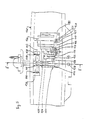
- the inner mirror designated as a whole by 1, is intended for a motor vehicle and is held by a support arm 3.
- the support arm is fastened with its end, not shown, to the inside of the windshield or the body of the vehicle in the usual way.
- the illustrated end 5, which points towards the direction of travel after installation of the interior mirror, carries a ball 7 which is positively encompassed by a bearing shell 12 of a mounting plate 10.
- the housing 30 of the inner mirror is pivotally attached, which has an opening for the ball 7 and the bearing shell 12 on the rear.
- the housing 30 On the side opposite the ball and facing the direction of travel, the housing 30 is closed with a mirror glass 40 which is held in a circumferential bead 32 which closes the interior of the housing 30 to the outside.
- the housing 30 with the bead 32 and the mirror glass 40 forms a one-piece component, which as a whole can be pivoted with respect to the mounting plate 10.
- the mirror glass 40 is provided on the back in a conventional manner with a mirror covering, which is not shown in detail here.
- the form fit between the bearing pan and the ball is usually so tight that the mirror 1 is held in rotation on the support arm 3 by the driver but can be rotated by hand to a position adapted to its seating position.
- the part 14 which extends within the housing 30 over the bearing shell 12 has two laterally projecting pins 16, 18 which are encompassed by tabs 36, 38 fastened to the rear wall of the housing, so that the housing 30 with a mirror 40 around the pin 16 , 18 extending pivot axis 32, indicated by dash-dotted lines in FIG. 1, is pivotable.
- an electronic circuit 24 which is only schematically indicated here, is mounted, which is connected in a manner not shown via electrical lines to the battery of the vehicle for power supply. Furthermore, no further electrical lines or conductor tracks are shown, which lead from the electronic circuit 24 to an electric motor 26 and a photo cell 28.
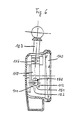
- An electric motor 26 is fastened on the auxiliary plate 22 on the side opposite the electronic circuit 24, the output shaft of which runs approximately parallel to the pivot axis 32. Furthermore, a cylinder 50 is rotatably mounted on the auxiliary plate 22 between the lower edge of the mounting plate 10 and the lower edge of the housing 30 so that its axis of rotation 52 lies with the center of the bearing shell 12 in a plane extending transversely to the pivot axis 32. For reasons of stability, as shown in FIG. 3, a cover plate 23 can be attached above the auxiliary plate 22 at a distance which is at least equal to the axial length of the cylinder 50, so that the cylinder 50 can be rotated in the auxiliary plate 22 and the cover plate 23 with pins not shown is held.
- the cylinder 50 On its end face adjacent to the auxiliary plate 22, the cylinder 50 has a toothing 54 over its circumference, which is connected via a reduction gear, generally designated 56, to that on the output shaft of the motor 26 attached screw 27 is in drive connection.
- the reduction gear 56 comprises a first pinion 58 which meshes with the worm 27 and which is coupled to a toothed section of smaller diameter of a second pinion 59.
- the toothed section of larger diameter of the second pinion 59 meshes with the toothing 54 of the cylinder 50.
- a circumferential groove 60 is cut into the jacket 51 of the cylinder 50 above the toothing 54, which, according to the development of the cylinder jacket shown in FIG. 4, has a central section 62 inclined against the axis 52, the ends of which intersect each other transversely to the axis 52 continue extending end portion 64, 66.
- the end section 64 accordingly has a greater axial distance from the auxiliary plate 22 than the end section 66, the middle section 62 of the circumferential groove 60 being able to run at an angle of 45 degrees relative to the axis 52.
- a pin 11 protrudes from the lower edge of the mounting plate 10, the free end of which is guided in the circumferential groove 60.
- two arms 68, 70 protrude from the jacket of the cylinder 50, in the path of which a switching arm 72, 76, each of a microswitch 74, 78, projects when the cylinder 50 rotates.
- the microswitches 74, 78 are fastened one above the other to the side of the cylinder 50 on the auxiliary plate 22 or the cover plate 23 and are connected to the electronic circuit 24 via lines (not shown).
- the housing 30 has an extension 31 on its lower middle part, in which an opening for the photocell 28 is provided. Furthermore, an on / off switch 33 and an adjusting button 35 for sensitivity control of the response threshold of the electronic circuit 24 to signals from the photocell 28 are provided in the extension 31.
- the interior mirror described works as follows: First, the driver aligns the mirror housing in the usual manner with respect to his sitting position in daylight so that he has a full view to the rear through the mirror glass 40. The mirror housing with mounting plate 10 twisted as a whole around the ball 7. The pin 11 is then captured in the end portion 66 of the circumferential groove 60.
- the photocell 28 detects the light falling on the mirror glass 40. If, for example, at dazzling from a following vehicle, especially at night, exceeds an intensity specified by adjusting the adjusting knob 35, the electronic circuit 24 responds to the signal coming from the photocell 28 and carries current of a certain polarity to the motor 26, which is reversible in its direction of rotation to. The motor 26 then causes the cylinder 50 to rotate clockwise via the reduction gear 56, so that the pin 11 reaches the end section 64 of the circumferential groove 60 from the end section 66 via the middle section 62. When it entered end section 64, arm 68 ran against switching arm 72 of microswitch 74, actuated it, whereupon microswitch 74 interrupted the current flow to motor 26.
- the mirror glass is now tilted against its fully reflecting position, so the mirror is dimmed and takes up a position as shown in FIG. 2.
- the mounting plate 10 has not changed its position on the ball 7, the housing 30 with mirror glass 40 is tilted against the mounting plate 10 about the pivot axis 32.
- the electronic circuit 24 responds again and supplies current of opposite polarity to the motor 26. This then causes the cylinder 50 to rotate in the opposite direction via the reduction gear 56, so that Pin 11 reaches end section 66 from end section 64. When it enters section 66, arm 70 moves against switching arm 76 of microswitch 78, which interrupts the current flow to the electric motor. The mirror has then returned to its normal exposed position, the housing 30 having been pivoted relative to the mounting plate 10 in the counterclockwise direction relative to the operating position shown in FIG. 2.
- response threshold for the electronic circuit 24 dependent on further parameters, for example on the signals from a further photocell which records the ambient light to determine the time of day or night and can be directed, for example, in the direction of travel.
- two posts 136, 138 are placed on the bottom of the housing 130 on both sides of the central plane EE, in which pins 116, 118 of a T-shaped mounting plate 110 are arranged in bores aligned transversely to the plane EE are held rotatably and define the pivot axis 132 of the housing 130.
- An electric motor 126 is mounted on a plate 122 so that its output shaft 120 rotates about an axis 125 parallel to the plane E-E.
- a pulley 121 sits on the output shaft 120 in a rotationally fixed manner and is coupled to a worm 127 via a belt drive 119.
- the worm 127 rotates parallel to the axis 125 and meshes with a tooth section, not shown in detail, of a shaft 104 which is supported at its opposite ends in blocks 102, 106 and is rotatable about an axis of rotation 152 by the worm 127, which is parallel to the pivot axis 132 extends.
- two switching cams are located in the axial direction alongside one another on the shaft 104 in the circumferential direction offset by approximately 180 degrees, each of which works against a switching arm 172, 176 each having an associated microswitch 174, 180 .
- Each of the two microswitches 174, 180 is electrically not shown in the power supply circuit for the motor 126.
- a cylinder 150 eccentric to the axis of rotation 152 is formed thereon, the jacket 151 of which surrounds the axis 152.
- the mounting plate 110 is non-rotatably clamped onto a support arm 103 of the interior mirror.
- an electronic circuit 24, not shown in detail, which receives the signals supplied by the photocell 128 and, depending on them, the motor 126 powered to its drive.
- Each of the two microswitches 174, 180 then switches off the current flow to the motor 126 by corresponding actuation of the switching arms 172, 176 by the associated cams when the cylinder 150 acting as an eccentric has reached one of its two rotational positions due to its housing-fixed mounting, which the Normal position or the dimming position of the mirror glass 140 correspond.
Landscapes
- Engineering & Computer Science (AREA)
- Multimedia (AREA)
- Mechanical Engineering (AREA)
- Rear-View Mirror Devices That Are Mounted On The Exterior Of The Vehicle (AREA)
- Optical Elements Other Than Lenses (AREA)
Priority Applications (3)
| Application Number | Priority Date | Filing Date | Title |
|---|---|---|---|
| EP85108548A EP0208008B1 (fr) | 1985-07-10 | 1985-07-10 | Rétroviseur intérieur de véhicule antiéblouissant à commande électro-optique |
| DE8585108548T DE3565382D1 (en) | 1985-07-10 | 1985-07-10 | Anti-glare interior vehicle mirror with electro-optical control |
| AT85108548T ATE37688T1 (de) | 1985-07-10 | 1985-07-10 | Fahrzeug-innenspiegel mit lichtelektrisch gesteuerter abblendung. |
Applications Claiming Priority (1)
| Application Number | Priority Date | Filing Date | Title |
|---|---|---|---|
| EP85108548A EP0208008B1 (fr) | 1985-07-10 | 1985-07-10 | Rétroviseur intérieur de véhicule antiéblouissant à commande électro-optique |
Publications (3)
| Publication Number | Publication Date |
|---|---|
| EP0208008A2 true EP0208008A2 (fr) | 1987-01-14 |
| EP0208008A3 EP0208008A3 (en) | 1987-03-25 |
| EP0208008B1 EP0208008B1 (fr) | 1988-10-05 |
Family
ID=8193609
Family Applications (1)
| Application Number | Title | Priority Date | Filing Date |
|---|---|---|---|
| EP85108548A Expired EP0208008B1 (fr) | 1985-07-10 | 1985-07-10 | Rétroviseur intérieur de véhicule antiéblouissant à commande électro-optique |
Country Status (3)
| Country | Link |
|---|---|
| EP (1) | EP0208008B1 (fr) |
| AT (1) | ATE37688T1 (fr) |
| DE (1) | DE3565382D1 (fr) |
Cited By (3)
| Publication number | Priority date | Publication date | Assignee | Title |
|---|---|---|---|---|
| GB2192600B (en) * | 1986-06-10 | 1990-08-08 | Bernhard Mittelhaeuser | Internal rear view mirror for motor vehicles |
| US7258455B2 (en) | 2004-05-05 | 2007-08-21 | Magna Donnelly Gmbh & Co. Kg | Interior mirror with a drive mechanism for adjusting a wedge mirror glass |
| DE10063597B4 (de) * | 2000-12-20 | 2008-05-15 | Volkswagen Ag | Einrichtung zum Abschalten der automatischen Abblendfunktion eines Rückblickspiegels |
Family Cites Families (4)
| Publication number | Priority date | Publication date | Assignee | Title |
|---|---|---|---|---|
| US4443057A (en) * | 1981-06-01 | 1984-04-17 | Gentex Corporation | Automatic rearview mirror for automotive vehicles |
| US4488777A (en) * | 1981-09-03 | 1984-12-18 | Gentex Corporation | Remotely actuated rearview mirror for automotive vehicles |
| JPS58126246U (ja) * | 1982-02-19 | 1983-08-27 | 株式会社東海理化電機製作所 | 防眩ミラ−の傾動装置 |
| WO1984001132A1 (fr) * | 1982-09-15 | 1984-03-29 | Anthony Stewart | Retroviseur |
-
1985
- 1985-07-10 DE DE8585108548T patent/DE3565382D1/de not_active Expired
- 1985-07-10 AT AT85108548T patent/ATE37688T1/de active
- 1985-07-10 EP EP85108548A patent/EP0208008B1/fr not_active Expired
Cited By (3)
| Publication number | Priority date | Publication date | Assignee | Title |
|---|---|---|---|---|
| GB2192600B (en) * | 1986-06-10 | 1990-08-08 | Bernhard Mittelhaeuser | Internal rear view mirror for motor vehicles |
| DE10063597B4 (de) * | 2000-12-20 | 2008-05-15 | Volkswagen Ag | Einrichtung zum Abschalten der automatischen Abblendfunktion eines Rückblickspiegels |
| US7258455B2 (en) | 2004-05-05 | 2007-08-21 | Magna Donnelly Gmbh & Co. Kg | Interior mirror with a drive mechanism for adjusting a wedge mirror glass |
Also Published As
| Publication number | Publication date |
|---|---|
| EP0208008B1 (fr) | 1988-10-05 |
| EP0208008A3 (en) | 1987-03-25 |
| ATE37688T1 (de) | 1988-10-15 |
| DE3565382D1 (en) | 1988-11-10 |
Similar Documents
| Publication | Publication Date | Title |
|---|---|---|
| EP0708999B2 (fr) | Dispositif d'entrainement d'une partie reglable d'un vehicule | |
| DE69505948T2 (de) | Bewegungsantrieb | |
| DE19839333C1 (de) | Antriebseinrichtung | |
| DE3211794C2 (fr) | ||
| DE3914911A1 (de) | Kippvorrichtung fuer einen fahrzeugscheinwerfer | |
| DE4021973C1 (fr) | ||
| DE3522204A1 (de) | Rueckspiegel | |
| DE4339279A1 (de) | Rückblickspiegel für Kraftfahrzeuge | |
| DE3500409C2 (fr) | ||
| DE68920696T2 (de) | Neigungsverstellvorrichtung für einen Sitz. | |
| DE3732413C2 (de) | Antriebsvorrichtung für ein Schwenkschiebedach eines Fahrzeugs | |
| DE69604435T2 (de) | Regelkreis zur Regelung des Antriebes eines Gleichstrommotors | |
| DE10014073B4 (de) | Sicherheitsgerät für motorbetriebene Fenster | |
| DE3213708C2 (fr) | ||
| DE3423520C2 (fr) | ||
| DE19832986A1 (de) | Antriebsvorrichtung für ein Sonnendach | |
| EP0865949B1 (fr) | Dispositif d'entraínement pour élément mobile de véhicule | |
| DE3915300C2 (fr) | ||
| EP0208008B1 (fr) | Rétroviseur intérieur de véhicule antiéblouissant à commande électro-optique | |
| DE19644658B4 (de) | Außenspiegel für ein Fahrzeug | |
| DE3915019C2 (fr) | ||
| DE8526206U1 (de) | Fahrzeug-Innenspiegel mit lichtelektrisch gesteuerter Abblendung | |
| DE3633010A1 (de) | Spiegelvorrichtung fuer ein fahrzeug | |
| DE3226435A1 (de) | Motorisch betriebener rueckblickspiegel fuer fahrzeuge | |
| DE3437775C2 (fr) |
Legal Events
| Date | Code | Title | Description |
|---|---|---|---|
| PUAI | Public reference made under article 153(3) epc to a published international application that has entered the european phase |
Free format text: ORIGINAL CODE: 0009012 |
|
| AK | Designated contracting states |
Kind code of ref document: A2 Designated state(s): AT BE CH DE FR GB IT LI LU NL SE |
|
| PUAL | Search report despatched |
Free format text: ORIGINAL CODE: 0009013 |
|
| AK | Designated contracting states |
Kind code of ref document: A3 Designated state(s): AT BE CH DE FR GB IT LI LU NL SE |
|
| 17P | Request for examination filed |
Effective date: 19870323 |
|
| 17Q | First examination report despatched |
Effective date: 19880224 |
|
| ITF | It: translation for a ep patent filed | ||
| GRAA | (expected) grant |
Free format text: ORIGINAL CODE: 0009210 |
|
| AK | Designated contracting states |
Kind code of ref document: B1 Designated state(s): AT BE CH DE FR GB IT LI LU NL SE |
|
| REF | Corresponds to: |
Ref document number: 37688 Country of ref document: AT Date of ref document: 19881015 Kind code of ref document: T |
|
| GBT | Gb: translation of ep patent filed (gb section 77(6)(a)/1977) | ||
| REF | Corresponds to: |
Ref document number: 3565382 Country of ref document: DE Date of ref document: 19881110 |
|
| ET | Fr: translation filed | ||
| PLBE | No opposition filed within time limit |
Free format text: ORIGINAL CODE: 0009261 |
|
| STAA | Information on the status of an ep patent application or granted ep patent |
Free format text: STATUS: NO OPPOSITION FILED WITHIN TIME LIMIT |
|
| 26N | No opposition filed | ||
| ITTA | It: last paid annual fee | ||
| PGFP | Annual fee paid to national office [announced via postgrant information from national office to epo] |
Ref country code: GB Payment date: 19940620 Year of fee payment: 10 |
|
| PGFP | Annual fee paid to national office [announced via postgrant information from national office to epo] |
Ref country code: FR Payment date: 19940718 Year of fee payment: 10 |
|
| PGFP | Annual fee paid to national office [announced via postgrant information from national office to epo] |
Ref country code: AT Payment date: 19940721 Year of fee payment: 10 |
|
| PGFP | Annual fee paid to national office [announced via postgrant information from national office to epo] |
Ref country code: DE Payment date: 19940727 Year of fee payment: 10 |
|
| PGFP | Annual fee paid to national office [announced via postgrant information from national office to epo] |
Ref country code: SE Payment date: 19940731 Year of fee payment: 10 Ref country code: NL Payment date: 19940731 Year of fee payment: 10 Ref country code: LU Payment date: 19940731 Year of fee payment: 10 |
|
| PGFP | Annual fee paid to national office [announced via postgrant information from national office to epo] |
Ref country code: BE Payment date: 19940804 Year of fee payment: 10 |
|
| PGFP | Annual fee paid to national office [announced via postgrant information from national office to epo] |
Ref country code: CH Payment date: 19940819 Year of fee payment: 10 |
|
| EPTA | Lu: last paid annual fee | ||
| EAL | Se: european patent in force in sweden |
Ref document number: 85108548.0 |
|
| PG25 | Lapsed in a contracting state [announced via postgrant information from national office to epo] |
Ref country code: LU Free format text: LAPSE BECAUSE OF NON-PAYMENT OF DUE FEES Effective date: 19950710 Ref country code: GB Effective date: 19950710 Ref country code: AT Effective date: 19950710 |
|
| PG25 | Lapsed in a contracting state [announced via postgrant information from national office to epo] |
Ref country code: SE Effective date: 19950711 |
|
| PG25 | Lapsed in a contracting state [announced via postgrant information from national office to epo] |
Ref country code: LI Effective date: 19950731 Ref country code: CH Effective date: 19950731 Ref country code: BE Effective date: 19950731 |
|
| BERE | Be: lapsed |
Owner name: HOHE K.G. Effective date: 19950731 |
|
| PG25 | Lapsed in a contracting state [announced via postgrant information from national office to epo] |
Ref country code: NL Effective date: 19960201 |
|
| GBPC | Gb: european patent ceased through non-payment of renewal fee |
Effective date: 19950710 |
|
| REG | Reference to a national code |
Ref country code: CH Ref legal event code: PL |
|
| NLV4 | Nl: lapsed or anulled due to non-payment of the annual fee |
Effective date: 19960201 |
|
| PG25 | Lapsed in a contracting state [announced via postgrant information from national office to epo] |
Ref country code: DE Effective date: 19960402 |
|
| EUG | Se: european patent has lapsed |
Ref document number: 85108548.0 |
|
| PG25 | Lapsed in a contracting state [announced via postgrant information from national office to epo] |
Ref country code: FR Effective date: 19960430 |
|
| REG | Reference to a national code |
Ref country code: FR Ref legal event code: ST |
|
| REG | Reference to a national code |
Ref country code: FR Ref legal event code: ST |
|
| REG | Reference to a national code |
Ref country code: FR Ref legal event code: ST |